Table of Contents
Troubleshooting

Related Manuals for GE Solar 8000M/i


Summary of Contents for GE Solar 8000M/i
- Page 1 GE Healthcare Solar 8000M/i patient monitor ™ Service Manual Software Version 5 Solar™ 8000M/i patient monitor English 2026266-004 (CD) 2026264-042C (paper) © 2007 General Electric Company All rights reserved.
- Page 2 NOTE: The information in this manual applies to Solar 8000i and Solar 8000M Patient Monitors. Due to continuing product innovation, specifications in this manual are subject to change without notice. NOTE: For technical documentation purposes, the abbreviation GE is used for the legal entity name, GE Medical Systems Information Technologies.
-
Page 3: Table Of Contents
System components ..........2-2 Solar 8000M/i patient monitoring system ....... . 2-2 Solar 8000M/i patient monitor . - Page 4 Exterior cleaning ..........4-4 Cleaning, disinfecting and storing GE ECG cables and leadwires ... . 4-5 Electrical safety tests .
- Page 5 Troubleshooting software updates ........5-19 2026265-075C Solar 8000M/i patient monitor...
- Page 6 Cables ............. 7-6 Solar 8000M/i patient monitor...
- Page 7 Solar 8000M/i patient monitor ........
- Page 8 Solar 8000M/i patient monitor 2026265-075C...
-
Page 9: Introduction
Introduction 2026265-075C Solar 8000M/i patient monitor... -
Page 10: Manual Information
Ordering manuals A paper copy of this manual will be provided upon request. Contact your local GE representative and request the part number on the first page of the manual. Solar 8000M/i patient monitor... -
Page 11: Safety Information
Introduction: Safety information Safety information Responsibility of the manufacturer GE is responsible for the effects of safety, reliability, and performance only if: Assembly operations, extensions, readjustments, modifications, or repairs are carried out by persons authorized by GE. The electrical installation of the relevant room complies with the requirements of the appropriate regulations. -
Page 12: Warnings, Cautions, And Notes
CAUTION indicates a potential hazard or unsafe practice which, if not avoided, could result in minor personal injury or product/property damage. NOTE provides application tips or other useful information to assure that you get the most from your equipment. Solar 8000M/i patient monitor 2026265-075C... -
Page 13: Equipment Symbols
NOTE: The rating of protection against electric shock (indicated by symbol for CF or BF) is achieved only when used with patient applied parts recommended by GE. TYPE CF APPLIED PART: Isolated (floating) applied part suitable for intentional external and internal application to the patient including direct cardiac application. - Page 14 This symbol indicates that this electronic information product does not contain any toxic or hazardous substance or elements above the maximum concentration value established by the Chinese standard SJ/T11363-2006, and can be recycled after being discarded, and should not be casually discarded. Solar 8000M/i patient monitor 2026265-075C...
-
Page 15: Service Information
Any unauthorized attempt to repair equipment under warranty voids that warranty. It is the user’s responsibility to report the need for service to GE or to one of their authorized agents. Failure on the part of the responsible individual, hospital, or... - Page 16 Introduction: Service information Solar 8000M/i patient monitor 2026265-075C...
-
Page 17: Equipment Overview
Equipment overview 2026265-075C Solar 8000M/i patient monitor... -
Page 18: System Components
Equipment overview: System components System components Solar 8000M/i patient monitoring system The Solar 8000M/i patient monitoring system consists of the following standard components: Solar 8000M/i processing unit Display Keypad and/or remote control Two possible acquisition devices: Tram-rac housing with acquisition module(s) -
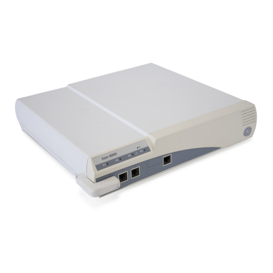
Page 19: Solar 8000M/I Patient Monitor
The patient monitor consists of a Solar 8000M/i processing unit with compatible display purchased from GE or another vendor. The processing unit is the center of the Solar 8000M/i patient monitoring system. It provides the user controls, the processors to communicate with various patient monitoring modules, and it analyzes patient data. -
Page 20: Ipanel Computer
UnityView remote display controller The UnityView remote display controller consists of a remote display controller with a compatible display purchased from GE or another vendor. The controller connects to the Unity Network and may be configured to display any patient waveforms broadcasted on the network for better visibility as a remote full-view display, or as an in-room telemetry display. -
Page 21: Tram-Rac Housing
Tram-rac 4A housing — holds one Tram module and two additional single-high modules. See the Tram-rac Housing Service Manual for additional information. Shown below is a Tram-rac 4A housing with a Tram module and two single parameter modules inserted. 005B 2026265-075C Solar 8000M/i patient monitor... -
Page 22: Patient Data Module (Pdm)
The data is collected from up to eight peripheral devices (not necessarily manufactured by GE), then the device transmits the formatted data to the Solar 8000M/i patient monitor. See the appropriate connectivity device service manual for additional information. -
Page 23: Prn 50/Prn 50-M Digital Writer
The use of an MPSO for a system will result in an enclosure leakage current equal to the sum of all the individual earth leakage currents of the system if there is an interruption of the MPSO protective earth conductor. 2026265-075C Solar 8000M/i patient monitor... -
Page 24: Remote Control Or Keypad
004B Remote displays Depending on your Solar 8000M/i configuration, there are up to two VGA (CRT/analog flat panel) ports and two DFP (digital flat panel) ports for remote viewing. Solar 8000M/i patient monitor... -
Page 25: Device Compatibility
For current information, contact your Service or Sales Representative. Acquisition modules The Solar 8000M/i patient monitor is compatible with the following acquisition modules. Patient Data Module (Nellcor OxiMax SpO Patient Data Module (Masimo SpO... -
Page 26: Peripheral Devices
Equipment overview: Device compatibility Tram Module w/ECG, Resp, CO, SpO2 (Masimo) tcpO2/pCO2 Module Respiratory Mechanics Module Impedance Cardiograph Module Peripheral devices The Solar 8000M/i patient monitor is compatible with the following peripheral devices. Device Interface Solar 8000M/i Remote M-Port Solar 8000M/i Keypad... -
Page 27: Unity Network Devices
Equipment overview: Device compatibility Unity Network devices The Solar 8000M/i patient monitor is compatible with the following Unity Network devices. Device Device ADU/Pager LAN MARS 5000/8000 ApexPro MUSE Aware Gateway Octacomm CDT-LAN RSVP CIC Pro C Solar 7000/8000 Dash 2000... -
Page 28: Interfacing With Other Peripheral Devices
Equipment overview: Device compatibility Interfacing with other peripheral devices The Solar 8000M/i patient monitor can interface with other peripheral bedside monitoring devices through an Unity Network ID connectivity device. For a list of supported devices, see the Unity Network Interface Device (ID) Service Manual. -
Page 29: Theory Of Operation
Equipment overview: Theory of operation Theory of operation The Solar 8000M/i patient monitor consists of a processor board, a power supply board, and a speaker. Software running on the processor board processes incoming data, services the communication channels and performs the general functions. System software may be updated using a... -
Page 30: Block Diagram Of Internal Connections
Equipment overview: Theory of operation Block diagram of internal connections Power Supply Assembly Processor Board Speaker 036B 2-14 Solar 8000M/i patient monitor 2026265-075C... -
Page 31: Processor Board
Equipment overview: Theory of operation Processor board The processor board processes acquired data for the generation of displayed information, audible alarms, and supports communication channels for the acquisition system, serial peripherals and the Unity Network. 035B 2026265-075C Solar 8000M/i patient monitor 2-15... - Page 32 MPC860 to assist in debugging and troubleshooting the processor operation. NOTE The MPC860 is +5V I/O tolerant on all of its pins except for the clock input. This is important because the signals from the TRAM-NET Hub are +5V signal levels. 2-16 Solar 8000M/i patient monitor 2026265-075C...
- Page 33 Address, Software level, product type, year and Power-Applied Indication. The I2C address for the EEPROM is “1010001x”. NOTE The serial EEPROM on the Solar 8000M/i processor PCB is not removable. Audio tone generation and output amplifier – The Solar 8000M/i processor PCB provides audio output for alarm and parameter tones.
- Page 34 20 pin MDR DFP connectors. RS-232 serial ports The RS-232 serial ports provide the interface to the iPanel computer (RS-232 1) and serial communication devices such as a touchscreen display. See the Communication System for detailed discussion. 2-18 Solar 8000M/i patient monitor 2026265-075C...
- Page 35 Hub must be +5V tolerant. Drivers and receivers – The DS8923 Dual Differential Driver/Receiver pair is used to convert the signals between the TRAM-NET differential RS-422 level and TTL levels. 2026265-075C Solar 8000M/i patient monitor 2-19...
- Page 36 The Ethernet receive pair are provided on pins 1 and 2 of the RJ-45 connector. NOTE The M-Port provides Host or Hub pinouts, not device side pin outs, so that a one-to-one Category 5 cable can be used to connect any Ethernet device up using an M-Port. 2-20 Solar 8000M/i patient monitor 2026265-075C...
- Page 37 RS-232 serial port connector pins to the common return plane. Since the serial ports are not electrically isolated, the need for maintaining isolation in the ESD protection scheme is not present. 2026265-075C Solar 8000M/i patient monitor 2-21...
-
Page 38: Power Supply
16.75 output voltage bus from which two outputs are developed. The main 16.75V output also provides external power to the RAC, data acquisition modules, and plug-in modules. Speaker The speaker generates sound for alarms, QRS detection, and SpO pulse tones. 2-22 Solar 8000M/i patient monitor 2026265-075C... -
Page 39: Installation
Installation 2026265-075C Solar 8000M/i patient monitor... -
Page 40: Back Panel Connections
Digital flat panel connectors Solar 8000M Power switch Ethernet connector RS-232 connectors 010C Power cord Voltage select TRAM-NET/ePort connectors Video connectors Digital flat panel connectors Solar 8000i NOTE The number of video connectors varies by configuration. Solar 8000M/i patient monitor 2026265-075C... -
Page 41: Tram-Net
If two Tram-racs are connected in any configuration, one must have a power supply. The following devices connect to either of the two TRAM-NET ports on the Solar 8000M/i monitor. The connector is a 9-pin, D-type. Tram-rac 4a housing with or without power supply Tram-rac 2 housing... - Page 42 013C CAUTION Equipment damage. Connect the Tram-rac housing to the Solar 8000M/i patient monitor before plugging the power cord into an AC outlet. Connecting these devices to a powered Solar 8000M/i patient monitor could damage connectors. Patient Data Module The Patient Data Module (PDM) is an acquisition device that connects to the Solar 8000i patient monitor via the ePort cable.
-
Page 43: Ethernet
The connector is a 15-pin, high density D type. WARNING Do not connect a monochrome display to the Solar 8000M/i patient monitor. Visual alarm indictors may not appear properly, resulting in a hazard to the patient. 014D 2026265-075C Solar 8000M/i patient monitor... -
Page 44: Dfp Vid 1 And 2
The connector is a 9-pin, D type. RS-232 2 The RS-232 2 serial connector provides a touchscreen interface. The connector is a 9-pin, D type. NOTE Use cable 2006733-00X for touchscreen connection. The cable supplied with the display will not work. Solar 8000M/i patient monitor 2026265-075C... -
Page 45: Front Panel Connectors And Indicators
M-Ports support AutoPort devices, but an AutoPort to M-Port adapter, PN 2001973-001, is required. The adapter must connect to the AutoPort device, not the M-Port host (the Solar 8000M/i patient monitor). The following devices connect directly to the M-Ports. The connector is an 8-pin RJ-45 type. - Page 46 (adult, neonatal, or operating room). A keypad holster mount is available for mounting under the display. NOTE The Solar 8000M/i requires an interface (remote control or keypad) with all display types. NOTE The error message WARNING: REMOTE MISMATCHED WITH MONITORING MODE displays if a mismatched keypad/remote control is connected to the Solar 8000M/i patient monitor.
- Page 47 The use of an MPSO for a system will result in an enclosure leakage current equal to the sum of all the individual earth leakage currents of the system if there is an interruption of the MPSO protective earth conductor. 2026265-075C Solar 8000M/i patient monitor...
-
Page 48: Indicators
After making all connections, plug the power cord into an AC wall outlet, turn the power switch to 1 (on), and turn on the display. The power LED illuminates and after about 10 seconds a display appears. If the Solar 8000M/i patient monitor does not work properly, refer to Chapter 5, “Troubleshooting”... -
Page 49: Tram-Net Communication
GE equipment throughout the hospital. NOTE GE highly recommends using a ‘private’ LAN to connect Unity products. The purpose of the Unity Network is to connect only Unity devices for the exchange of patient data and room-to-room communication. -
Page 50: Ethernet Communication
GE equipment throughout the hospital. Depending on the construction of the hospital, thick-net, thin- net, or CAT-5 twisted pair cabling is used. The Solar 8000M/i is designed to be used with twisted-pair cabling. Consult GE when trying to interface with either thick-net or thin-net cabling. -
Page 51: Network Terms
A subnet is a logical segment of a larger network that shares a common IP address range as defined by a subnet mask. Proper subnetting can improve the performance and security of a network. Solar 8000 series monitors support classful subnetting. 2026265-075C Solar 8000M/i patient monitor 3-13... - Page 52 Installation: Ethernet communication 3-14 Solar 8000M/i patient monitor 2026265-075C...
-
Page 53: Maintenance And Checkout
Maintenance and checkout 2026265-075C Solar 8000M/i patient monitor... -
Page 54: Maintenance Schedule
395 days of operation. This message is a reminder that it is time to perform preventive maintenance procedures on the monitor. Perform all of the maintenance procedures listed under “Manufacturer Recommendations” above. Solar 8000M/i patient monitor 2026265-075C... -
Page 55: Visual Inspection
Maintenance and checkout: Visual inspection Visual inspection The Solar 8000M/i patient monitor and its components should be carefully inspected prior to installation, once every 12 months thereafter, and each time the equipment is serviced. Carefully inspect the equipment for physical damage to the case, the display screen, and the keypad. -
Page 56: Cleaning
Cleaning Cleaning precautions NOTE “Cleaning, disinfecting and storing GE ECG cables and leadwires” on page 4-5 for instructions specific to GE ECG cables and leadwires. Use one of the following approved solutions: Cidex solution Sodium hypochlorite bleach (diluted) Mild soap (diluted) -
Page 57: Cleaning, Disinfecting And Storing Ge Ecg Cables And Leadwires
Cleaning, disinfecting and storing GE ECG cables and leadwires NOTE These instructions supersede all cleaning/disinfecting instructions for GE ECG Cables and Leadwires. All safety statements and notes in the manual still apply. Cleaning or disinfecting 1. Remove cables and leadwires from the handheld device or system before cleaning. - Page 58 Alcohol-based cleaning agents Sodium salts Never autoclave or steam clean cables or leadwires. Storage Store in a dry well-ventilated area. Vertically hang cables and leadwires. Do not coil leadwires or cables tightly around any medical device. Solar 8000M/i patient monitor 2026265-075C...
- Page 59 NOTE For additional information, refer to the How to Reach Us page of the manual for contact information. Also see the GE Handheld Medical Devices Cleaning, Disinfecting, and Storage addendum. 2026265-075C Solar 8000M/i patient monitor...
-
Page 60: Electrical Safety Tests
The sole responsibility rests with the individual or institution using the equipment. GE service personnel may, at their discretion, follow the procedures provided in this manual as a guide during visits to the equipment site. -
Page 61: Set Up
Connection.” These tests determine whether the device's exposed metal and power inlet's earth (ground) connection have a power ground fault condition. Perform the test method below that is required by your country/local governing safety organization. 2026265-075C Solar 8000M/i patient monitor... - Page 62 For equipment with a power supply cord the impedance between the protective earth pin in the mains plug and the ground tabs of the Video In connector which is protectively earthed shall not exceed 0.2 ohms. 4-10 Solar 8000M/i patient monitor 2026265-075C...
-
Page 63: Ground (Earth) Wire Leakage Current Tests
6. Read the current leakage indicated on DMM. NOTE If either reading is greater than the appropriate specification below, the device under test fails. Contact GE Technical Support. 300 μA (0.3 volts on the DMM), and the device under test is powered from 100-120 V/50-60 Hz. -
Page 64: Enclosure Leakage Current Test
Maintenance and checkout: Electrical safety tests Enclosure leakage current test This test pertains to the Solar 8000M/i, part of the monitoring system. Perform this test to measure current leakage through exposed conductive surfaces on the device under test during normal operation. -
Page 65: Patient (Source) Leakage Current Test
11. Set the power switch of the device under test to OFF. Patient (source) leakage current test This test pertains to the Solar 8000M/i, part of the monitoring system. This procedure only applies to Class I (grounded/earthed) equipment, and measures the leakage current from the ECG/RESP connector then the SpO2 connector of the device to ground. -
Page 66: Patient (Sink) Leakage Current Test
Connect the SpO2 Test Body to the blue SpO2 connector of the device under test. Patient (sink) leakage current test This test pertains to the Solar 8000M/i, part of the monitoring system. This procedure only applies to Class I (grounded/earthed) equipment, and measures the leakage current from a mains voltage source into the ECG/RESP connector then the SpO2 connector. -
Page 67: Test Completion
NOTE If either reading is greater than the appropriate specification below, the device under test fails. Contact GE Technical Support. 10 μA (0.01 volts on the DMM) at 120 VAC using the test body. 20 μA (0.02 volts on the DMM) at 240 VAC using the test body. -
Page 68: Checkout Procedure
Patient Data Module and associated communication networks. For other input modules checkout procedures, refer to their appropriate service manual. GE recommends that all checkout procedures be performed upon receipt of the device, once a year thereafter, after any upgrade, any time the main enclosure is disassembled, or a part is repaired or replaced. -
Page 69: Set Up
3. Using the patient simulator and patient cables, configure the monitor display with as many waveforms as possible. Refer to the appropriate patient monitor operator's manual, if necessary. 4. The waveforms should look clean (no noise). 2026265-075C Solar 8000M/i patient monitor 4-17... -
Page 70: Procedures
Maintenance and checkout: Checkout procedure Procedures Solar 8000M/i Unity View display NOTE This check only applies to Solar 8000M systems with product code 3S and 3T. Refer to the specific manufacturer’s documentation. Touchscreen Verify that touching a parameter box displays the screen information for that parameter. - Page 71 Slot 4 Series 7000 Waveform B (Left Side or Module) Parameter 7 1. The top displayed trace on the monitor is present unless AVR, AVL, or AVF leads are used, then lead II is output. 2026265-075C Solar 8000M/i patient monitor 4-19...
- Page 72 2. From the MAIN menu, select MORE MENUS > VIEW OTHER PATIENTS > SELECT A BED TO VIEW. Verify that the list includes beds other than your own. 3. Select another bed and verify that the selected bed’s data is displayed. 4-20 Solar 8000M/i patient monitor 2026265-075C...
- Page 73 10. Exit Boot Code. Unity Network ID Unity Network ID connectivity device checkout procedures, see the Unity Network Interface Device (ID) service manual. Printer Press Graph Go/Stop and verify that the printer responds correctly. 2026265-075C Solar 8000M/i patient monitor 4-21...
-
Page 74: Parameter Tests
7. At the patient monitor, select the ECG parameter window to display the ECG menu at the bottom of the screen. Select PACE 1: or PACE 2:. 9. Inject an asychronous pacemaker pulse with the simulator. 4-22 Solar 8000M/i patient monitor 2026265-075C... - Page 75 The monitor displays a respiration rate reading of 30 ±2 breaths per minute. 4. Set the respiration waveform to lead I at the monitor, LA at the simulator, and observe the same conditions as in step 3. 2026265-075C Solar 8000M/i patient monitor 4-23...
- Page 76 T2 connector. 7. Observe that the T2 reading appears on the patient monitor is between 36.6 and 37.4. 8. Disconnect the temperature sensor adaptor and temperature cable from the acquisition device and the simulator. 4-24 Solar 8000M/i patient monitor 2026265-075C...
- Page 77 1. Verify that 2 AA alkaline batteries are installed in the NELLCOR SRC-MAX Pulse Oximetry functional tester. 2. Connect the SRC-MAX to the SpO connector on the module. On the SRC-MAX, verify that the IR and RED LED indicators are both lit. 2026265-075C Solar 8000M/i patient monitor 4-25...
- Page 78 Heart rate = 200 bpm Light = HIGH %SpO = 90 MOD = LOW 11. Verify the following SpO readings for saturation and pulse rate: Saturation (%):90 ± 2 Rate (bpm): 200 ± 3 (194 to 206) 4-26 Solar 8000M/i patient monitor 2026265-075C...
- Page 79 Set the MODULATION switch to LOW. Set the RATE switch to 38. 9. Verify the following SpO2 readings for saturation and pulse rate: Saturation (%): 81 ± 2 Rate (bpm): 38 ± 2% (37 to 39) 2026265-075C Solar 8000M/i patient monitor 4-27...
- Page 80 NBP cuff is used in this procedure, it must be tightly wrapped around a rigid cylinder or pipe. 5. Connect a manometer and NBP cuff to the NBP connector on the front of the acquisition device. Connect to acquisition device 454A 4-28 Solar 8000M/i patient monitor 2026265-075C...
- Page 81 The second line of text on the CAL GAIN menu item changes to INFLATING. Then, the acquisition device starts pumping up the pressure bulb or cuff displayed pressures increase on both the monitor display and the manometer. 2026265-075C Solar 8000M/i patient monitor 4-29...
- Page 82 (shown below). They should resemble the waveforms in the following figures. Note that there are two Marker Out traces shown. The top trace shows the frequency of the pulses; the bottom trace shows the pulse width. 4-30 Solar 8000M/i patient monitor 2026265-075C...
- Page 83 Signal Name Brown ECG_ANALOG_OUT BP_ANALOG_OUT Orange NO_CONNECTION Yellow MARKER_RETURN Shield DRAIN WIRE Green ANALOG_RETURN Blue NO_CONNECTION Violet DEFIB_SYNC_MARKER_IN Gray DEFIB_SYNC_MARKER_OUT Signal pin: 1 Brown wire Ground pin: 6 Green wire Time/division: 0.2s Volts/division: 0.5v 023A 2026265-075C Solar 8000M/i patient monitor 4-31...
- Page 84 Marker Out (Pulse Width) Signal pin: 9 Gray wire Ground pin: 4 Yellow wire Time/division: 5ms Volts/division: 1v 026A NOTE The Marker Out amplitude and pulse width are configured at 10v and 10ms respectively from the factory. 4-32 Solar 8000M/i patient monitor 2026265-075C...
- Page 85 Descriptions DEFIB_MARKER_OUT Digital defibrillator output synchronization signal DEFIB_MARKER_IN Digital defibrillator input signal AGND1 Signal Ground DGND Signal Ground AGND2 Signal Ground Front View of BP_ANALOG_OUTPUT Analog BP/OUTPUT Module ECG_ANALOG_OUTPUT Analog ECG output signal 039A 2026265-075C Solar 8000M/i patient monitor 4-33...
- Page 86 024A NOTE The Marker Out amplitude and pulse width are configured at 5V and 10ms respectively from the factory. To change these settings refer to the Calibration chapter of your TRAM modules service manual. 4-34 Solar 8000M/i patient monitor 2026265-075C...
- Page 87 Observe negative spikes in the R-waves while waves before the the jumper is installed. Note that the spikes are jumper is installed. small, and can be difficult to see at times. 040A 4. Remove the jumper. 2026265-075C Solar 8000M/i patient monitor 4-35...
-
Page 88: Completion
Maintenance and checkout: Checkout procedure Completion Test additional modules using procedures found in the service manual that accompanied the module. Disconnect all test equipment. Return the monitor and acquisition device to service. 4-36 Solar 8000M/i patient monitor 2026265-075C... -
Page 89: Maintenance Checklist
4-4 1. ____ Exterior cleaning 2. ____ Cleaning the display 3. ____ Cleaning the touch screen display 4. ____ Cleaning disinfecting and storing GE ECG cables and leadwires “Electrical safety tests” on page 4-8 1. ____ Power outlet test 2. - Page 90 ____ SpO2 functions (Nellcor OxiMax) ____ SpO2 functions (Nellcor OxiSmart, Tram only) 8. ____ NBP calibration check 9. ____ Defib/sync and analog output test (Patient Data Module) ____ Defib/sync and analog output test (Tram Module) 4-38 Solar 8000M/i patient monitor 2026265-075C...
-
Page 91: Repair Log
Maintenance and checkout: Repair Log Repair Log Unit serial number: Institution name: Date Maintenance or repair Technician 2026265-075C Solar 8000M/i patient monitor 4-39... - Page 92 Maintenance and checkout: Repair Log 4-40 Solar 8000M/i patient monitor 2026265-075C...
-
Page 93: Troubleshooting
Troubleshooting 2026265-075C Solar 8000M/i patient monitor... -
Page 94: Terms Used
“performing cold start” appears, begin the cold start again. Continue (main code) CONTINUE is a Main Code menu selection that appears after a successful software download. It allows the user to continue downloading other files without resetting the monitor. Solar 8000M/i patient monitor 2026265-075C... -
Page 95: Monitor Memory
4. Select Start Patient Monitoring. Country selection This is a Boot Code setting. The choices are France, Germany, or Default which chooses a particular set of GE factory defaults. These defaults are used when changing the unit type (Adult-ICU, OR, or Neonatal). -
Page 96: Service Menus
Unity Network problems. If you change the factory assigned Ethernet address, you must record all other Ethernet addresses used on your network to avoid duplication. Set up second Ethernet Port Same as Set up first Ethernet Port. Solar 8000M/i patient monitor 2026265-075C... - Page 97 Cardiopulmonary Features, etc.) and change the monitor software level. A unique password is required for each option and to change the software level or Ethernet address. Fax a password request to GE Customer Relationship Center at (414) 362-3250 to obtain a password. You must provide your product serial number and Ethernet address.
-
Page 98: Main Code Service Mode Menu
Provides a list of various test patterns and colors that can be used to calibrate the display. When finished, select RESTART System. PATIENT-MONITOR TYPE Select the type of monitor desired, i.e., adult, neonatal or operating room. See Chapter 6, “Configuration” , for detailed procedures. Solar 8000M/i patient monitor 2026265-075C... - Page 99 This menu selection is used to turn a password requirement ON or OFF for entry into the MONITOR DEFAULTS menu section described above. If selected, the password will be the same as the SERVICE MODE MENU password. 2026265-075C Solar 8000M/i patient monitor...
-
Page 100: Monitor Settings
An incorrect internet address may also prevent the monitor from viewing other monitors on the network. Whether or not this can occur depends on the network topology at the installed site. Solar 8000M/i patient monitor 2026265-075C... -
Page 101: Time And Date
This menu selection allows changes to the time and date and may affect the time and date for the entire monitoring network. Refer to Chapter 6, Configuration, for detailed procedures. WARNING Loss of patient history. This menu should rarely be used because patient histories will be lost. 2026265-075C Solar 8000M/i patient monitor... -
Page 102: Fault Analysis
Calibration The Solar 8000M/i patient monitor is factory calibrated and requires no calibration in the field. The only field adjustable switch is S1 on the power supply. It selects the range for the AC mains input, but should not need to be changed. -
Page 103: Ac Line Voltage Test
The voltage measurements should be as follows: 1. 120 VAC (± 10 VAC) between either “hot” contact and ground. 2. 210 to 230 VAC between the two “hot” contacts. ❷ ❶ ❶ GROUND 022A 2026265-075C Solar 8000M/i patient monitor 5-11... -
Page 104: Troubleshooting Procedure
Patient data loss. This procedure is intended for use by service personnel with advanced troubleshooting skills. The consequences of the following steps may cause loss of patient data and disruption of the entire Unity Network. 5-12 Solar 8000M/i patient monitor 2026265-075C... -
Page 105: Problems And Solutions
Check the connection between the video display and the patient monitor and correct, if necessary, or The quality of the display is replace the video display with a known good one. If the problem is not corrected, replace the processor not good. pcb. 2026265-075C Solar 8000M/i patient monitor 5-13... - Page 106 3. Force an alarm from another monitor to test if the speaker is functioning. If the central station displays a NO COMM message for one patient, do the following: Cycle power to the Solar 8000M/i processing unit. Patient data from the Solar Check for a loose connection between the patient monitor and the Ethernet cable.
- Page 107 4. Disconnect and securely reconnect the remote control from the monitor to reset the remote control. 5. Replace remote control with a known good one. 6. Replace processor pcb in patient monitor with a known good one. 2026265-075C Solar 8000M/i patient monitor 5-15...
-
Page 108: Led Troubleshooting
M-Port Ethernet LEDs on processor PCB DS15/Green Link “I hear all talking on Ethernet.” ON when receive path is OK from hub to the Solar 8000M/i M-Port DS16/Green Link “I hear all talking on Ethernet.” ON when receive path is OK from hub... - Page 109 Troubleshooting: Troubleshooting procedure DS1, DS2, DS3, and DS4 DS5 and DS7 DS 6 DS 19 DS 18 DS 17 DS 16 DS 15 050B DS14 DS13, DS12, DS9, and DS8 2026265-075C Solar 8000M/i patient monitor 5-17...
- Page 110 Flashes opposite DS6 (twice per second) 1. Because “I hear when I am talking,” the “talking” LED flashes with the “hearing” LED, but the “hearing” LED will also flash alone when it “hears someone else talking.” 5-18 Solar 8000M/i patient monitor 2026265-075C...
-
Page 111: Troubleshooting Software Updates
5. If the Ethernet address needs to be changed in Boot Code, a unique password is required to access Change Ethernet Address in the Options Menu. Fax a password request to GE Customer Relationship Center at 877-633-8181 to obtain a password. You will need to provide your product serial number and Ethernet address. -
Page 112: Error Messages
“WARNING: The EEPROM data was found to be either INVALID or Following the EEPROM dump, restore data: uninitialized. GE Medical Systems Information Technologies 1. Restore Ethernet address and IP address as requested by factory defaults will be stored in both the EEPROM and the the Boot Code. - Page 113 Remove the PDM from the patient monitoring system immediately and send to service for repair. See the Patient Data Module service manual for troubleshooting information. 2026265-075C Solar 8000M/i patient monitor 5-21...
-
Page 114: Reviewing Error/Event Logs
This procedure describes how to review the error logs of a monitor or Tram module. The error logs may also be transferred over the network to a central station and copied onto diskette for further review or sent to GE personnel for review. The transferring procedure “Copying Error Log Files”... -
Page 115: Useful Error Data
Indicates the impact of the event/problem on the system. Date The date the event or problem occurred. Time The time the event or problem occurred. Error Number A sequential number that is used to identify each event or problem. 2026265-075C Solar 8000M/i patient monitor 5-23... - Page 116 The event or error was such that the task is not able to go on. Recovery was not possible. This always is followed by a warm start. Forced Restart The system was restarted by a known condition (internet address change, video test, etc). 5-24 Solar 8000M/i patient monitor 2026265-075C...
- Page 117 Refer to the software compatibility listing in the SOFTWARE REVISION window. SERVICE PATIENT DATA MODULE NOTE The monitor may be referred to as a display or scope in the error code descriptions. 2026265-075C Solar 8000M/i patient monitor 5-25...
- Page 118 Text describing the viewed bedside 2 = Full View name is shown. Network Connection Change 0 = Stops communicating 1 = Starts communicating TRAM/ECG Module Connection Change 0 = Stops communicating 1 = Starts communicating 5-26 Solar 8000M/i patient monitor 2026265-075C...
-
Page 119: Get Error Logs
Get error logs Get logs via PC using netUpdate These instructions describe how to copy log files from a Solar 8000M/i patient monitor to a PC using one of the following configurations: PC or PC laptop connected to a Solar 8000M/i patient monitor PC or PC laptop connected to the Unity Network MC network. - Page 120 Unity Network MC network Ethernet tap. 3. Power on the PC. 4. Continue with the instructions, “Change the PC’s IP address” on page 29. 5-28 Solar 8000M/i patient monitor 2026265-075C...
- Page 121 Double-click System and select the Computer Name tab. Network Identification tab. Record the full computer name: __________________________________________ Close all open windows. Restart the PC. Continue with the instructions, “Disable firewall or networking services” on page 30. 2026265-075C Solar 8000M/i patient monitor 5-29...
- Page 122 4. Verify that the Service status reads Stopped. 5. Select OK and close all windows. 6. Repeat these instructions for all VPN, wireless network cards or any firewall protection programs running on your PC. 5-30 Solar 8000M/i patient monitor 2026265-075C...
- Page 123 7. In the netUpdate window, select the patient monitor name or IP address from the device list. Click Refresh until the IP address or patient monitor name displays. 8. Click Get Log or Get All Logs. 2026265-075C Solar 8000M/i patient monitor 5-31...
- Page 124 9. Select the folder you created for log files, then click OK. 10. The log file displays and a message at the top of the netUpdate window displays a message that the log retrieval was successful. 5-32 Solar 8000M/i patient monitor 2026265-075C...
-
Page 125: Configuration
Configuration 2026265-075C Solar 8000M/i patient monitor... -
Page 126: Configuring A Patient Monitor
Set Line Frequency (optional, Boot Code) Set Defib Sync Voltage and Pulse Width (optional, Boot Code) Set Country Selection (Boot Code) Set Language (Boot Code) Calibrate Touchscreen After completing all necessary procedures, perform the “Checkout procedure” on page 4-16. Solar 8000M/i patient monitor 2026265-075C... -
Page 127: Set Unit Name
↑ ↓ 052A 4. Use the TRIM KNOB control to select and change each character. Up to five characters may be entered. 5. Select SET BED NUMBER and press the TRIM KNOB control to exit. 2026265-075C Solar 8000M/i patient monitor... -
Page 128: Patient Monitor Type
4. Rotate TRIM KNOB control to select the type of environment the monitor will be used in. 5. Press TRIM KNOB control to exit. Your selection displays at the top of the screen after the time. Solar 8000M/i patient monitor 2026265-075C... -
Page 129: Set Graph Locations
Check the programmed alarms and manual graph locations at the monitor. Ensure the care unit name is the same in the monitor and in the central station. Ensure the central station serial number and LAN address are programmed correctly. 2026265-075C Solar 8000M/i patient monitor... -
Page 130: Admit Menu
(e.g., July 4 = 0407). 3. Select MENU SETUP > ADMIT MENU. ↑ ↓ 027A 4. Use the TRIM KNOB control to select the function of the monitor. 5. Press TRIM KNOB control to exit. Solar 8000M/i patient monitor 2026265-075C... -
Page 131: Set Line Frequency
Hz or 60 Hz line frequency. Set defib sync voltage and pulse width The Solar 8000M/i patient monitor controls the analog out signal used to trigger a defibrillator. Refer to the defibrillator manufacturer’s manual for the required pulse amplitude and duration. -
Page 132: Set Country Selection
5. Touch and hold each of the 4 Xs as they appear per on-screen instructions. Completion The monitor is now ready for normal operation. At this time, perform the “Checkout Procedure” found in Chapter 3, Maintenance. Solar 8000M/i patient monitor 2026265-075C... -
Page 133: Advanced User Procedures
3. To set the time, select SET TIME and use the TRIM KNOB control to change the time. The time displays as a 24-hour military clock. 4. To set the date, select SET DATE and use the TRIM KNOB control to change the date. 2026265-075C Solar 8000M/i patient monitor... -
Page 134: Change Software Level
If you want to change the software to a higher level or add software options, it must be done in Boot Code using a unique password. Fax a password request to GE Customer Relationship Center at (414) 362-3250 to obtain a password. You must provide your product serial number and Ethernet address. - Page 135 3. Enter password using the TRIM KNOB control to select the day and month from monitor screen with leading zeros (e.g., July 4 = 0407). 4. Select MONITOR SETTINGS. 5. Select STORE DEFAULTS FOR NETWORK TRANSFER. 6. Selects YES to the confirmation popup menu. 2026265-075C Solar 8000M/i patient monitor 6-11...
- Page 136 If another set of defaults is desired, the user must manually select it from the RECALL DEFAULTS menu. After copying monitor defaults from another bed (the server monitor), verify that the defaults were transferred and arrhythmia levels are as desired. 6-12 Solar 8000M/i patient monitor 2026265-075C...
- Page 137 The server and client monitors are set to SOFTWARE FEATURE MISMATCH different software levels (i.e., Basic, Cardiac). ERROR COPYING UNIT DEFAULTS - The server and client monitors are set to COUNTRY CODE MISMATCH different country codes (i.e., DEFAULT, FRANCE, or GERMANY). 2026265-075C Solar 8000M/i patient monitor 6-13...
-
Page 138: Change Ethernet Address
Ethernet addresses used on your network to avoid duplication. Fax a password request to GE Customer Relationship Center at 877-633- 8181 to obtain a password. You must provide your product serial number and Ethernet address. (The Ethernet address displays in the Boot Code banner information.) -
Page 139: Set Internet Address
Ethernet address in this procedure if the factory-assigned internet address is corrupted. NOTE GE highly recommends using a ‘private’ LAN to connect Unity products. The purpose of the Unity Network is to connect only Unity devices for the exchange of patient data and room-to-room communication. -
Page 140: Power Cycle
Calculate internet address To generate an internet address from an Ethernet address, GE simply converts the last three bytes of the Ethernet address from hex to decimal. This combines the unique identifier along with the network ID to produce the entire internet address. -
Page 141: Field Replaceable Units
Field replaceable units 2026265-075C Solar 8000M/i patient monitor... -
Page 142: Ordering Parts
To order parts, contact Service Parts at the address or telephone number listed on the “How to Reach Us...” page found in the front of this manual. For the latest parts information, including substitutions, obsolescence and compatibility, please visit our Parts ID Portal website at: http://egems.gehealthcare.com/partsiduser/gems/Welcome.jsp Solar 8000M/i patient monitor 2026265-075C... -
Page 143: Field Replaceable Units
“Hardware kit” on page 7-4.) Note: The processor pcb is dual video and has dual function TRAMNET/e-Port connection. It is compatible with all previous hardware configurations of Solar 8000M/i but requires software version 5.1 Wire Harness (Processor to Power Supply) 422812-002... -
Page 144: Hardware Kit
SCR MACH FLHD M3 X 6MM SS N8.25 GRAY SCR DIN912 M3 X 8MM ZINC VIBRA GASKET EMI SHIELD FOAM NA-C2 E67 3.3 GASKET EMI SHIELD FOAM NA-C2 E67 9.5 GASKET EMI SHIELD FOAM NA-C2 E67 12.8 Solar 8000M/i patient monitor 2026265-075C... - Page 145 Field replaceable units: Hardware kit 2026265-075C Solar 8000M/i patient monitor...
-
Page 146: Keypads And Remote Controls
Description Item number 6 Foot Serial Cable for iPanel interface 2000727-001 10 Foot Serial Cable for iPanel interface 2000727-002 15 Foot Serial Cable for iPanel interface 2000727-003 25 Foot Serial Cable for iPanel interface 2000727-004 Solar 8000M/i patient monitor 2026265-075C... -
Page 147: Disassembly
Electrostatic discharge (ESD) precautions All external connectors of the Solar 8000M/i patient monitor are designed with protection from ESD damage. However if the module requires service, exposed components and assemblies inside are susceptible to ESD damage. -
Page 148: Disassembly Procedures
1. Remove four painted screws on the sides of the unit. NOTE Use the #1 Phillips head screwdriver. 2. Slide the cover directly back toward the rear to clear the right angle piece of the M-port ethernet cable, then lift cover off. Solar 8000M/i patient monitor 2026265-075C... - Page 149 1. Remove the cover. (See “Cover” on page 7-8.) If your unit has a Solar 8000M/i patient monitor to Patient Data Module (SPA), then: a. Remove 2 screws from the SPA. b. Disconnect the SPA from the TRAMNET 1 port.
- Page 150 Doing so will result in patient data loss. If the monitor is on a network, verify that the time and date is automatically set by the network time master. 7-10 Solar 8000M/i patient monitor 2026265-075C...
- Page 151 Then desolder the battery and solder in a new lithium battery. Speaker 1. Remove the cover. 2. Using a metric hex or allen wrench with ball end, unscrew two screws. 3. Remove speaker from chassis. 2026265-075C Solar 8000M/i patient monitor 7-11...
- Page 152 Field replaceable units: Disassembly 7-12 Solar 8000M/i patient monitor 2026265-075C...
-
Page 153: Appendix A - Technical Specifications
Appendix A – Technical specifications 2026265-075C Solar 8000M/i patient monitor... -
Page 154: Solar 8000M/I Patient Monitor
Solar 8000M/i patient monitor Due to continual product innovation, specifications and standards are subject to change without notice. The following specifications are accurate as of the date of this publication, and pertain to Solar 8000M/i patient monitor. Specifications are based on a complete system including a 15 inch monitor (display*). - Page 155 5.6 kg (12.3 lb) Warranty Standard warranty is one year. Other options are available. Display* The display is ordered separately from the Solar 8000M/i processing unit. Display size: 15” to 19” typical Display types: Analog and digital flat panel, CRT displays...
- Page 156 Due to continual product innovation and standards changes, compliance to applicable standards is subject to change. The following are accurate as of the date of this publication. For additional information, contact your local GE representative. Solar 8000M/i with Patient Data Module: IEC/EN/UL 60601-1 CAN/CSA C22.2 No.
-
Page 157: Tram-Rac 2 And 4A Module Housings
Tram-rac 4A housing with optional power supply Power requirements: 90 to 270 VAC, 50/60 Hz, single-phase Power consumption: 70 Watts maximum, 40 Watts typical Low-voltage shutdown: 85 VAC Cooling: Convection Heat dissipation: 238 Btu/hr maximum (70 Watts) 2026265-075C Solar 8000M/i patient monitor... - Page 158 14.5 cm (5.7 in) Depth: 31.8 cm ( 12.5 in) without power supply 37.1 cm (14.6 in) with power supply Weight: 2.7 kg (6 lb) without power supply 3.4 kg (7.5 lb) with power supply Solar 8000M/i patient monitor 2026265-075C...
-
Page 159: Tram Modules And Solar Parameter Functionality
Frequency response: Tram 451, 451M, 451N, 851, 851M, 851N: Adult mode: 0.05 to 100 Hz OR mode: 0.05 to 25 Hz Neonatal mode: 0.5 to 40 Hz All others: 0.05 or 0.5 to 100Hz (user selectable) 2026265-075C Solar 8000M/i patient monitor... - Page 160 Pacemaker detection/rejection: Input voltage range ±2 mV to ±700 mV Input pulse width 0.1 ms to 2 ms 10 μs to 100 μs Rise time Over/under shoot 2 mV (maximum) Solar 8000M/i patient monitor 2026265-075C...
- Page 161 (ICP) - mean umbilical arterial (UAC) - systolic, diastolic and mean umbilical venous (UVC) - mean special pressure (SP) - mean Transducer requirements: ±2.5 V dc ±0.1% Excitation voltage: 50 μV/V/cm Hg Transducer output: 2026265-075C Solar 8000M/i patient monitor...
- Page 162 Appendix A – Technical specifications: Tram modules and Solar parameter functionality Range: –25 mmHg to 300 mmHg A-10 Solar 8000M/i patient monitor 2026265-075C...
- Page 163 Mean pressure range: Adult: 20 to 260 mmHg Pediatric: 20 to 235 mmHg Neonatal: 20 to 125 mmHg Cuff pressure range: Adult: 0 to 300 mmHg Pediatric: 0 to 250 mmHg Neonatal: 0 to 150 mmHg 2026265-075C Solar 8000M/i patient monitor A-11...
- Page 164 User-selectable upper and lower limits for systolic, diastolic, and mean pressures Pulse oximetry Tram 200SL, 400SL, 600SL, 800A, 800SL and 300 (support Ohmeda probes) Tram 250SL, 450SL, 650SL, 850A and 850SL (support Nellcor and GE probes) Parameters monitored: Arterial oxygen saturation (SpO2) and peripheral pulse rate (PPR) Probe types: GE, Nellcor, Ohmeda.
- Page 165 Interference Detected, Low Light, Check Probe, Low Signal Quality, Probe Off Patient, Replace Bad Probe, Service the Module Pulse oximetry Tram 451 and 851 (support GE Medical Systems Information Technologiesprobes) Tram 451M and 851M (support Masimo SET probes) Tram 451N and 851N (support Nellcor Oxismart XL probes)
- Page 166 -10°C to 50°C (14°F to 122°F) Storage humidity: 0% to 95% (noncondensing) Physical specifications (Tram modules) Height: 8.1 cm (3.2 in) Width: 11.4 cm (4.5 in) Depth: 29.5 cm (11.6 in) Weight: 2.1 kg (4.7 lb) A-14 Solar 8000M/i patient monitor 2026265-075C...
-
Page 167: Dual Temperature Module (400 And 700 Series
Appendix A – Technical specifications: Dual temperature module (400 and 700 series) Dual temperature module (400 and 700 series) Refer to the BP/CO/Temperature Modules Service Manual for Technical Specifications 2026265-075C Solar 8000M/i patient monitor A-15... -
Page 168: Capnostat Mainstream Co Module
Sensor designed to withstand 6-foot (2 m) drops to a tile surface Airway adapters Adult: Reusable adult airway adapter, less than 5 cc dead space (pn 412341-001) Low volume: Reusable airway adapter, less than 0.5 cc deadspace (pn 412342-001) A-16 Solar 8000M/i patient monitor 2026265-075C... - Page 169 Depth: 28.6 cm (11.25 in) Width: 11.4 cm (4.5 in) Weight: 0.50 kg (1.11 lb) Sensor Height: 4.0 cm (1.60 in) Depth: 2.2 cm (.87 in) Width: 3.7 cm (1.45 in) Weight: <28 grams (<1 oz) 2026265-075C Solar 8000M/i patient monitor A-17...
-
Page 170: Svo 2 Module
-10°C to 50°C (14°F to 122°F) Relative humidity: 0% to 95% (noncondensing) Physical specifications Height: 4.1 cm (1.6 in) Depth: 28.6 cm (11.2 in) Width: 11.4 cm (4.5 in) Weight: 0.50 kg (1.11 lb) A-18 Solar 8000M/i patient monitor 2026265-075C... -
Page 171: Icg Module
Forced Air Heat Dissipation: 9W maximum Compatible host monitors, Tram-racs Host Monitor/Tram-rac Software Version Solar 7000: 7A or later Solar 8000: 7A or later Tram-rac 4A: 6A or later Warranty One year (accessories may differ) 2026265-075C Solar 8000M/i patient monitor A-19... -
Page 172: Bis/Eeg Module
4.0 cm (1.6 in) Width: 11.4 cm (4.5 in) Depth: 28.6 cm (11.25 in) Weight: 0.52 Kg (1.15 lb) Cooling Method: Natural convection Heat Dissipation: 20Btu/Hr (6W), maximum Warranty One year (accessories may differ) A-20 Solar 8000M/i patient monitor 2026265-075C... -
Page 173: Patient Data Module
Appendix A – Technical specifications: Patient Data Module Patient Data Module Refer to the Patient Data Module service manual for technical specifications. Solar SpO Masimo SET module Refer to the Solar SpO Masimo SET Module service manual for technical specifications. 2026265-075C Solar 8000M/i patient monitor A-21... -
Page 174: Solar 8000M/I Display
Appendix A – Technical specifications: Solar 8000M/i display Solar 8000M/i display The Solar 8000M/i patient monitor is currently available with the following GE displays: 15-inch, medical-grade, digital flat panel display with touchscreen 15-inch, medical-grade, analog/digital flat panel display with or... -
Page 175: Non-Medical Grade Displays
The party assembling or modifying the medical electrical system is responsible to insure compliance with IEC 60601-1-1. Therefore, if GE installs a Solar 8000M/i system with a computer-grade display, GE is responsible for meeting the specification. As a result GE will only install non-medical grade displays with appropriate isolation transformers. -
Page 176: Required Specifications For Non-Medical Grade Crt Displays
Appendix A – Technical specifications: Solar 8000M/i display Required specifications for non-medical grade CRT displays The following are required specifications: Electrical: Horizontal: Sync Rate: 48.4 KHz (*see note) Sync Input: TTL negative Vertical: Refresh Rate: 60 Hz (*see note) Sync Input:... -
Page 177: Recommended Specifications For Non-Medical Grade Crt Displays
Appendix A – Technical specifications: Solar 8000M/i display Recommended specifications for non-medical grade CRT displays The following are recommended specifications: Monitor (Display) Size: 12-inch to 19-inches typical Input Voltage Range: 90-254 VAC 50/60 Hz Controls: On/Off, Brightness, Contrast Environmental: Operating... -
Page 178: Required Specifications For Non-Medical Grade Digital Flat Panel Displays
Appendix A – Technical specifications: Solar 8000M/i display Required specifications for non-medical grade digital flat panel displays The following are required specifications: Electrical: Horizontal: Sync Rate: 48.4 KHz (*see note) Sync Input: TTL negative Vertical: Refresh Rate: 60 Hz (*see note) -
Page 179: Recommended Specifications For Non-Medical Grade Digital Flat Panel Displays
Appendix A – Technical specifications: Solar 8000M/i display Recommended specifications for non-medical grade digital flat panel displays The following are recommended specifications: Monitor (Display) Size: 15-inch to 21-inches typical Display Characteristics: Viewing angle ± 70° horizontal minimum; ± 70° vertical minimum... - Page 180 Appendix A – Technical specifications: Solar 8000M/i display A-28 Solar 8000M/i patient monitor 2026265-075C...
-
Page 181: Appendix B - Electromagnetic Compatibility
Appendix B – Electromagnetic compatibility 2026265-075C Solar 8000M/i patient monitor 8000i Patient Monitor... -
Page 182: Electromagnetic Compatibility (Emc
The Solar 8000M/i is intended for use in the electromagnetic environment specified below. It is the responsibility of the customer or user to assure that the Solar 8000M/i is used in such an environment. Emissions test Compliance Electromagnetic environment – guidance... -
Page 183: Guidance And Manufacturer's Declaration - Electromagnetic Immunity
The Solar 8000M/i is intended for use in the electromagnetic environment specified below. It is the responsibility of the customer or user to assure that the Solar 8000M/i is used in such an environment. Immunity test EN 60601 test level Compliance level Electromagnetic environment –... - Page 184 If abnormal performance is observed, additional measures may be necessary, such as re-orienting or relocating the equipment. Over the frequency range 150 KHz to 80 MHz, field strengths should be less than 3 V/m. Solar 8000M/i patient monitor 2026265-075C...
-
Page 185: Recommended Separation Distances
The Solar 8000M/i is intended for use in the electromagnetic environment on which radiated RF disturbances are controlled. The customer or the user of the Solar 8000M/i can help prevent electromagnetic interference by maintaining a minimum distance between portable and mobile RF communications equipment (transmitters) and the Solar 8000M/i as recommended below, according to the maximum output power of the communications equipment. -
Page 186: Compliant Cables And Accessories
The table below lists cables, transducers, and other applicable accessories with which GE claims EMC compliance. NOTE Any supplied accessories that do not affect EMC compliance are not included. - Page 187 3.6 m / 12 ft Edwards Truwave Adapter Cable 3.6 m / 12 ft Spectramed Transducer Adapter Cable 3.6 m / 12 ft Utah Disposable Transducers (DPT, DP2, DP3) Spectramed Transducers (TC-MQ) Abbott Transpac-III Transducers 2026265-075C Solar 8000M/i patient monitor...
- Page 188 BIS/EEG cables BIS DSC w/PIC Plus EEG DSC w/leadwires EEG DSC Extension Cable 6 m / 20 ft TC cable Radiometer E5280 Patient Cable cable Abbott Optical Module Sensor Cable 2.4 m / 8 ft Accessories Solar 8000M/i patient monitor 2026265-075C...
- Page 189 1.8 m / 6 ft Analog Video Cable 1.8 m / 6 ft 18-inch Medical Grade Flat Panel Display 15-inch Medical Grade Flat Panel Display 15-inch Medical Grade Flat Panel Display 15-inch Medical Grade Flat Panel Display with Touch 2026265-075C Solar 8000M/i patient monitor...
- Page 190 Category Description Maximum length 15-inch Medical Grade iPanel Computer Keyboard (USB) Mouse (USB optical) PS2 Y Adapter Cable Kit, HHP 3800PDF USB Scanner with USB Cable 3800PDF Scanner Cable (USB, Type A) 10 ft. B-10 Solar 8000M/i patient monitor 2026265-075C...
- Page 192 + 86 21 5257 4650 Fax: + 1 414 355 3790 Fax: + 49 761 45 43 - 233 Fax: + 86 21 5208 2008 GE Medical Systems Information Technologies, a General Electric Company, going to market as GE Healthcare. www.gehealthcare.com 0459...