Cisco Firepower 4100 Series Hardware Installation Manual
Hide thumbs
Also See for Firepower 4100 Series:
- Command reference manual (421 pages) ,
- Hardware installation manual (82 pages) ,
- Manual (42 pages)
Table of Contents
Advertisement
Advertisement
Chapters
Table of Contents

Related Manuals for Cisco Firepower 4100 Series


Summary of Contents for Cisco Firepower 4100 Series
- Page 1 Cisco Firepower 4110, 4120, 4140, and 4150 Hardware Installation Guide First Published: 2016-03-31 Last Modified: 2018-11-16 Americas Headquarters Cisco Systems, Inc. 170 West Tasman Drive San Jose, CA 95134-1706 http://www.cisco.com Tel: 408 526-4000 800 553-NETS (6387) Fax: 408 527-0883...
- Page 2 Cisco has more than 200 offices worldwide. Addresses and phone numbers are listed on the Cisco website at www.cisco.com/go/offices. Cisco and the Cisco logo are trademarks or registered trademarks of Cisco and/or its affiliates in the U.S. and other countries. To view a list of Cisco trademarks, go to this URL: www.cisco.com...
-
Page 3: Table Of Contents
Supported SFP/SFP+ and QSFP Transceivers Hardware Specifications Product ID Numbers Power Cord Specifications C H A P T E R 2 Installation Preparation Installation Warnings Safety Recommendations Maintain Safety with Electricity Cisco Firepower 4110, 4120, 4140, and 4150 Hardware Installation Guide... - Page 4 Remove and Replace the Fan Module Remove and Replace the SSD Remove and Replace the Power Supply Module Connect the DC Power Supply Module Secure the Power Cord on the AC Power Supply Module Cisco Firepower 4110, 4120, 4140, and 4150 Hardware Installation Guide...
-
Page 5: Features
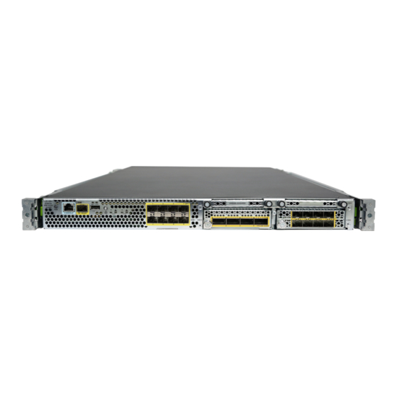
Power Cord Specifications, on page 28 Features The Cisco Firepower 4100 series security appliance is a standalone modular security services platform. It is capable of running multiple security services simultaneously and so is targeted at the data center as a multiservice platform. - Page 6 Figure 1: Firepower 4100 Series See the Cisco Interactive Library for a video that displays the features and components of the Firepower 4100. The following table lists the features for the Firepower 4100 series. Table 1: Firepower 4100 Series Features Feature 4110...
- Page 7 Two (1+1) power supply module slots Ships with one 400-W AC power supply Ships with two 400-W AC power supply modules modules Hot-swappable Hot-swappable DC power supply Yes (optional) Redundant power Yes 1+1 Cisco Firepower 4110, 4120, 4140, and 4150 Hardware Installation Guide...
-
Page 8: Overview
Package Contents The following figure shows the package contents for the Firepower 4100. Note that the contents are subject to change and your exact contents might contain additional or fewer items. Cisco Firepower 4110, 4120, 4140, and 4150 Hardware Installation Guide... -
Page 9: Serial Number Location
2 cable management brackets Welcome to the Cisco Firepower 4100 Serial Number Location The serial number for the Firepower 4100 series chassis is located on the pullout asset card on the front panel. Cisco Firepower 4110, 4120, 4140, and 4150 Hardware Installation Guide... -
Page 10: Front Panel
You can also view additional model information on the compliance label located on the bottom of the chassis. Figure 4: Compliance Label on the 4100 Chassis Front Panel The following figure shows the front panel of the Firepower 4100. Cisco Firepower 4110, 4120, 4140, and 4150 Hardware Installation Guide... -
Page 11: Front Panel Leds
Network module 3 The 10-G network module is Note shown. Front Panel LEDs The following figure and table describe the Firepower 4100 front panel LEDs. Figure 6: Front Panel LEDs Cisco Firepower 4110, 4120, 4140, and 4150 Hardware Installation Guide... -
Page 12: Rear Panel
• Off—No connection or port is not in use. • Amber—No link or network failure. • Green—Link up. • Green, flashing—Network activity. Rear Panel The following figure shows the rear panel of the Firepower 4100. Cisco Firepower 4110, 4120, 4140, and 4150 Hardware Installation Guide... - Page 13 Note After removing power from the chassis either by moving the power switch to OFF or unplugging the power cord, wait at least 10 seconds before turning power back ON. Cisco Firepower 4110, 4120, 4140, and 4150 Hardware Installation Guide...
-
Page 14: Network Modules
You can fit four copper SFPs in either the top row of ports or the bottom row of ports. Both rows cannot be populated at the same time, because of the port row spacing. Figure 8: FPR4K-NM-8X10G Cisco Firepower 4110, 4120, 4140, and 4150 Hardware Installation Guide... -
Page 15: 40-G Network Module
The following figure shows the front panel of the 40-G network module (FPR4K-NM-4X40G.) The FPR4K-NM-4X40G is a single-wide module that supports hot swapping. The four ports are numbered left to right. Note The FPR4K-NM-4X40G is NEBS-compliant. Figure 9: FPR4K-NM-4X40G Cisco Firepower 4110, 4120, 4140, and 4150 Hardware Installation Guide... -
Page 16: Hardware Bypass Network Modules
• Inline interfaces—Connection to any two like ports (10 G to 10 G for example) on one network module, across network modules, or fixed ports. For each network segment you want to monitor inline, connect the cables to pairs of interfaces. Cisco Firepower 4110, 4120, 4140, and 4150 Hardware Installation Guide... -
Page 17: 1-G Network Module With Hardware Bypass
The following figure shows the front panel view of the 1-G fail-to-wire network module (FPR4K-NM-8X1G-F). Pair ports 1 and 2, 3 and 4, 5 and 6, and 7 and 8 to form hardware bypass paired sets. Figure 10: FPR-NM-8X1G-F Cisco Firepower 4110, 4120, 4140, and 4150 Hardware Installation Guide... -
Page 18: 40-G Network Module With Hardware Bypass
The FPR4K-NM-2X40G-F is a single-wide module that does not support hot swapping. The two ports are numbered left to right. Pair the two ports to create a hardware bypass paired set. Figure 11: FPR4K-NM-2X40G-F Cisco Firepower 4110, 4120, 4140, and 4150 Hardware Installation Guide... - Page 19 QSFP for the 40-G BASE-SR-4. We recommend the following Cisco OM3 MTP/MPO cables. Table 3: Cisco Cables Cisco Part Number Cable Length CAB-ETH-40G-5M CAB-ETH-40G-10M 10 m CAB-ETH-40G-20M 20 m Cisco Firepower 4110, 4120, 4140, and 4150 Hardware Installation Guide...
-
Page 20: 1-G Sx/10-G Sr/10-G Lr Network Module With Hardware Bypass
The 1-G SX /10-G SR/10-G LR network modules have the following insertion loss measurements. Insertion loss measurements help you to troubleshoot the network by verifying cable installation and performance. Table 4: 1-G SX Network Module (FPR4K-NM-6X1SX-F) Operating Mode Typical Maximum Cisco Firepower 4110, 4120, 4140, and 4150 Hardware Installation Guide... - Page 21 150 m 4700 (OM4) 200 m Table 6: 10-G LR Network Module (FPR4K-NM-6X10LR-F) Operating Mode Typical Maximum Insertion loss Normal 1.2 dB 1.6 dB Hardware bypass 1.5 dB 1.9 dB Cisco Firepower 4110, 4120, 4140, and 4150 Hardware Installation Guide...
-
Page 22: Power Supply Modules
13 A (at 100 V AC) The system power requirements are lower than the power Note supply module capabilities. See Hardware Specifications, on page 23 for the system power requirements. Maximum output power 1100 W Cisco Firepower 4110, 4120, 4140, and 4150 Hardware Installation Guide... - Page 23 The following figure shows the two-color power supply LEDs. The LEDs are located on the upper right side. Figure 13: Power Supply Module LEDs Amber FAIL LED Green OK LED The following table describes the power module supply LEDs. Cisco Firepower 4110, 4120, 4140, and 4150 Hardware Installation Guide...
-
Page 24: Fan Modules
Remove and Replace the Fan Module, on page 58 for the procedure for removing and replacing the fan module. The following figure shows the location of the fan LED. Figure 14: Fan LED Cisco Firepower 4110, 4120, 4140, and 4150 Hardware Installation Guide... -
Page 25: Supported Sfp/Sfp+ And Qsfp Transceivers
Caution For some earlier production Firepower 4100 series chassis, you may experience difficulty using the GLC-TE SFP on the management port or fixed ports. Contact Cisco TAC for support if you encounter problems with the GLC-TE SFP. Cisco Firepower 4110, 4120, 4140, and 4150 Hardware Installation Guide... - Page 26 10G Cu, 2m SFP-H10GB-CU2M 10G Cu, 2.5m SFP-H10GB-CU2-5M 10G Cu, 3m SFP-H10GB-CU3M 10G Cu, 5m SFP-H10GB-CU5M 10G Cu, 7m SFP-H10GB-ACU7M 10G Cu, 10m SFP-H10GB-ACU10M 10G AOC, 1m SFP-10G-AOC1M 10G AOC, 2m SFP-10G-AOC2M Cisco Firepower 4110, 4120, 4140, and 4150 Hardware Installation Guide...
-
Page 27: Hardware Specifications
Fits standard 19-in. (48.3-cm) square-hole rack Rack mount Yes, mount rails included 4-post EIA-310-D rack Dimensions (H x W 1.75 x 16.89 x 29.7 in. (4.44 x 42.90 x 75.43 cm) x D) Cisco Firepower 4110, 4120, 4140, and 4150 Hardware Installation Guide... - Page 28 1° C reduction of maximum for every 1000 ft (305 m) above sea level Nonoperating: -40° to 149° F (-40° to 65° Humidity Operating and nonoperating: 5 to 95 % noncondensing Cisco Firepower 4110, 4120, 4140, and 4150 Hardware Installation Guide...
-
Page 29: Product Id Numbers
6000 ft (1829 Operating altitude: 0 to 13,000 ft (3962 Product ID Numbers The following table lists all of the PIDs associated with the Firepower 4100 series. Table 12: Firepower 4100 Series PIDs Description FPR4110-AMP-K9 Cisco Firepower 4110 AMP appliance, 1 RU, two... - Page 30 Firepower hardware accessory kit containing rack mounts and cables FPR4K-ACC-KIT= Firepower hardware accessory kit containing rack mounts and cables (spare) FPR4K-ASA-CAR License to add carrier security to ASA on the Firepower 4100 Cisco Firepower 4110, 4120, 4140, and 4150 Hardware Installation Guide...
- Page 31 1100W AC power supply module (spare) FPR4K-PWR-DC-950 950W DC power supply module FPR4K-PWR-DC-950= 950W DC power supply module (spare) FPR4K-RACK-MNT Rack mount kit FPR4K-RACK-MNT= Rack mount kit (spare) FPR4K-SSD-BBLKD SSD slot carrier Cisco Firepower 4110, 4120, 4140, and 4150 Hardware Installation Guide...
-
Page 32: Power Cord Specifications
Only the approved power cords or jumper power cords provided with the security appliance are supported. The following power cords are supported. Figure 16: Argentina CAB-9K10A-AR Plug: IRAM 2073 Cord set rating: 10 A, 250 V Connector: IEC 60320-C15 Cisco Firepower 4110, 4120, 4140, and 4150 Hardware Installation Guide... - Page 33 Plug: EL223 (NBR 14136) Cord set rating: 10 A, 250 V Connector: EL 701B (EN 60320/C13) Figure 19: Brazil PWR-CORD-G2A-BZ Plug: NBR 14136 Cord set rating: 10 A, 250 V Connector: IEC 60320-C13 Cisco Firepower 4110, 4120, 4140, and 4150 Hardware Installation Guide...
- Page 34 Figure 21: Denmark CAB-TA-DN Plug: DK3 Cord set rating: 10 A, 250 V Connector: IEC 60320-C13 Figure 22: Europe CAB-AC-EUR Plug: CEE 7/7 Cord set rating: 10 A, 250 V Connector: IEC 60320-C15 Cisco Firepower 4110, 4120, 4140, and 4150 Hardware Installation Guide...
- Page 35 Figure 24: Israel CAB-250V-10A-IS Plug: SI-32 Cord set rating: 10 A, 250 V Connector: IEC 60320-C13 Figure 25: Italy CAB-9K10A-IT Plug: CEI 23-16/VII Cord set rating: 10 A, 250 V Connector: IEC 60320-C15 Cisco Firepower 4110, 4120, 4140, and 4150 Hardware Installation Guide...
- Page 36 Plug: NEMA L6-20P Cord set rating: 15 A, 250 V Connector: IEC 60320-C13 Figure 28: Japan CAB-TA-JP Plug: NEMA5-15P/JIS 8303 Cord set rating: 12 A, 125 V Connector: IEC 60320-C15 Cisco Firepower 4110, 4120, 4140, and 4150 Hardware Installation Guide...
- Page 37 Plug: BS1363A/SS145 Cord set rating: 10 A, 250 V Connector: IEC 60320-C13 Figure 31: South Africa CAB-9K10A-SA Plug: SABS 164 Cord set rating: 10 A, 250 V Connector: IEC 60320-C15 Cisco Firepower 4110, 4120, 4140, and 4150 Hardware Installation Guide...
- Page 38 Figure 33: Taiwan CAB-9K10A-TWN Plug: CNS10917-2 Cord set rating: 10 A, 125 V Connector: IEC 60320-C15 Figure 34: United Kingdom CP-PWR-CORD-UK Plug: BS1363A/SS145 Cord set rating: 10 A, 250 V Connector: IEC 60320-C13 Cisco Firepower 4110, 4120, 4140, and 4150 Hardware Installation Guide...
-
Page 39: Installation Preparation
SAVE THESE INSTRUCTIONS Warning Statement 1028—More Than One Power Supply This unit might have more than one power supply connection. All connections must be removed to de-energize the unit. Cisco Firepower 4110, 4120, 4140, and 4150 Hardware Installation Guide... - Page 40 Before working on equipment that is connected to power lines, remove jewelry (including rings, necklaces, and watches). Metal objects will heat up when connected to power and ground and can cause serious burns or weld the metal object to the terminals. Cisco Firepower 4110, 4120, 4140, and 4150 Hardware Installation Guide...
-
Page 41: Safety Recommendations
Statement 19—TN Power Warning The device is designed to work with TN power systems. Safety Recommendations Observe these safety guidelines: • Keep the area clear and dust-free before, during, and after installation. Cisco Firepower 4110, 4120, 4140, and 4150 Hardware Installation Guide... -
Page 42: Maintain Safety With Electricity
• Use the chassis within its marked electrical ratings and product usage instructions. Prevent ESD Damage ESD occurs when electronic components are improperly handled, and it can damage equipment and impair electrical circuitry, resulting in intermittent or complete failure. Cisco Firepower 4110, 4120, 4140, and 4150 Hardware Installation Guide... -
Page 43: Site Environment
• Front and rear doors—If your rack includes closing front and rear doors, the doors must have 65 percent open perforated area evenly distributed from top to bottom to permit adequate airflow. Cisco Firepower 4110, 4120, 4140, and 4150 Hardware Installation Guide... - Page 44 • Baffles can help to isolate exhaust air from intake air, which also helps to draw cooling air through the chassis. The best placement of the baffles depends on the airflow patterns in the rack. Experiment with different arrangements to position the baffles effectively. Cisco Firepower 4110, 4120, 4140, and 4150 Hardware Installation Guide...
-
Page 45: Unpack And Inspect The Chassis
• Invoice number of shipper (see the packing slip) • Model and serial number of the damaged unit • Description of damage • Effect of damage on the installation Cisco Firepower 4110, 4120, 4140, and 4150 Hardware Installation Guide... -
Page 46: Rack-Mount The Chassis
(such as power supplies, fans, or cards); these types of handles are not designed to support the weight of the unit. This procedure describes how to install the Firepower 4100 series security appliance in a rack using the rack kit from the accessory kit that shipped with the chassis. - Page 47 Secure the inner rail to the side of the chassis using 1 M3X6mm screw. e) Install the second inner rail to the opposite side of the chassis and secure with the other M3X6mm screw. Cisco Firepower 4110, 4120, 4140, and 4150 Hardware Installation Guide...
- Page 48 Securing plate shown pulled back to open position Note Works with square slots, 7.1 mm holes, and 10-32 threaded holes Rack post Step 4 Install the slide rails into the rack: Cisco Firepower 4110, 4120, 4140, and 4150 Hardware Installation Guide...
- Page 49 Inner rail attached to chassis Outer rail attached to rack post Step 6 Use the captive screws on the front of the mounting brackets to fully secure the chassis to the rack. Cisco Firepower 4110, 4120, 4140, and 4150 Hardware Installation Guide...
-
Page 50: Ground The Chassis
• Two star lock washers for the 10-32 x .375-in. screws used to secure the ground lug • You need the following items from the accessory kit: • Ground lug #6 AWG, 90 degree, #10 post Cisco Firepower 4110, 4120, 4140, and 4150 Hardware Installation Guide... - Page 51 Figure 40: Attach the Grounding Lug Step 6 Make sure that the lug and cable do not interfere with other equipment. Cisco Firepower 4110, 4120, 4140, and 4150 Hardware Installation Guide...
-
Page 52: Install The Fips Opacity Shield
Because the FIPS opacity shield covers the serial number on the chassis, you need to copy the serial number on a label and attach it to the chassis where it can be retrieved or viewed easily before you install the FIPS opacity shield. You need the serial number when you call Cisco TAC. Before you begin You need the following to install the FIPS opacity shield: •... - Page 53 (3 per side) Step 4 Attach a cable management bracket to each slide rail locking bracket using the four 8-32 x .375-in. countersink Phillips head screws provided in the accessory kit. Cisco Firepower 4110, 4120, 4140, and 4150 Hardware Installation Guide...
- Page 54 7 below. Step 6 Route the cables through the openings in the cable management brackets. Cisco Firepower 4110, 4120, 4140, and 4150 Hardware Installation Guide...
- Page 55 Figure 43: Route the Cables Through the Cable Management Brackets Step 7 Attach the FIPS opacity shield to the cable management brackets using the four 8-32 x .375-in. countersink Phillips head screws provided in the FIPS kit. Cisco Firepower 4110, 4120, 4140, and 4150 Hardware Installation Guide...
- Page 56 OFF or unplugging the power cord, wait at least 10 seconds before turning power back ON. Step 12 See the quick start guide for your operating software for further configuration information: • Cisco ASA for Firepower 4100 Quick Start Guide Cisco Firepower 4110, 4120, 4140, and 4150 Hardware Installation Guide...
-
Page 57: Connect Cables, Turn On Power, And Verify Connectivity
Mount and Connect Connect Cables, Turn on Power, and Verify Connectivity • Cisco Firepower Threat Defense for Firepower 4100 Quick Start Guide Connect Cables, Turn on Power, and Verify Connectivity Take note of the following warnings: Warning Statement 1021—SELV Circuit To avoid electric shock, do not connect safety extra-low voltage (SELV) circuits to telephone-network voltage (TNV) circuits. - Page 58 Although non-Cisco SFP transceivers are allowed, we do not recommend using them because they have not Note been tested and validated by Cisco. Cisco TAC may refuse support for any interoperability problems that result from using an untested third-party SFP transceiver. See Supported SFP/SFP+ and QSFP Transceivers, on page for a list of supported Cisco transceivers.
-
Page 59: Remove And Replace The Network Module
Do not operate the system unless all cards, faceplates, front covers, and rear covers are in place. Warning Statement 1030—Equipment Installation Only trained and qualified personnel should be allowed to install, replace, or service this equipment. Cisco Firepower 4110, 4120, 4140, and 4150 Hardware Installation Guide... - Page 60 Do one of the following: a) Power down the chassis by moving the power switch to the OFF position (if removing a network module that does not support hot swapping). Cisco Firepower 4110, 4120, 4140, and 4150 Hardware Installation Guide...
- Page 61 What to do next Follow the procedures in the FXOS Configuration Guide to connect to the network module and make sure that it has been discovered correctly by the Firepower 4100. Cisco Firepower 4110, 4120, 4140, and 4150 Hardware Installation Guide...
-
Page 62: Remove And Replace The Fan Module
To remove a fan module, face the rear of the chassis, and grasp the handle of the fan module. Step 2 Squeeze the handle to disengage the latches on the left and right of the fan module. Step 3 Pull the fan module out of the chassis. Cisco Firepower 4110, 4120, 4140, and 4150 Hardware Installation Guide... -
Page 63: Remove And Replace The Ssd
(EMI) that might disrupt other equipment; and they direct the flow of cooling air through the chassis. Do not operate the system unless all cards, faceplates, front covers, and rear covers are in place. Cisco Firepower 4110, 4120, 4140, and 4150 Hardware Installation Guide... - Page 64 Step 3 To remove an SSD, face the front of the chassis, loosen the two captive screws on the SSD, and gently pull it out of slot 1 of the chassis. Cisco Firepower 4110, 4120, 4140, and 4150 Hardware Installation Guide...
-
Page 65: Remove And Replace The Power Supply Module
When stranded wiring is required, use approved wiring terminations, such as closed-loop or spade-type with upturned lugs. These terminations should be the appropriate size for the wires and should clamp both the insulation and conductor. Cisco Firepower 4110, 4120, 4140, and 4150 Hardware Installation Guide... - Page 66 Ultimate disposal of this product should be handled according to all national laws and regulations. Warning Statement 1045—Short-Circuit Protection This product requires short-circuit (overcurrent) protection to be provided as part of the building installation. Install only in accordance with national and local wiring regulations. Cisco Firepower 4110, 4120, 4140, and 4150 Hardware Installation Guide...
- Page 67 Press the latch found on the lower right of the power supply to disengage the power supply. Step 3 Place your other hand under the power supply module to support it while you slide it out of the chassis. Cisco Firepower 4110, 4120, 4140, and 4150 Hardware Installation Guide...
-
Page 68: Connect The Dc Power Supply Module
When stranded wiring is required, use approved wiring terminations, such as closed-loop or spade-type with upturned lugs. These terminations should be the appropriate size for the wires and should clamp both the insulation and conductor. Cisco Firepower 4110, 4120, 4140, and 4150 Hardware Installation Guide... - Page 69 Only trained and qualified personnel should be allowed to install, replace, or service this equipment. Warning Statement 1040—Product Disposal Ultimate disposal of this product should be handled according to all national laws and regulations. Cisco Firepower 4110, 4120, 4140, and 4150 Hardware Installation Guide...
- Page 70 (+) lead and the negative (–) lead must always match the (+) and (–) labels on the power distribution unit. Figure 50: DC Input Power Cable Lug Cisco Firepower 4110, 4120, 4140, and 4150 Hardware Installation Guide...
- Page 71 Make sure that all site power and grounding requirements have been met. Step 4 To remove the plastic cover from the terminal block, insert a flat screw driver on the side of the plastic cover and pry it off. Cisco Firepower 4110, 4120, 4140, and 4150 Hardware Installation Guide...
- Page 72 Step 7 For easier cable management, insert the negative lead cable first. Replace the grounding lug with the cable in the following order—wire terminal, then the screw with the captive washer. Cisco Firepower 4110, 4120, 4140, and 4150 Hardware Installation Guide...
- Page 73 Replace the terminal block plastic cover. The plastic cover is slotted and keyed to fit correctly over the terminal block. This cover should always be in place when power is applied to the terminals. Cisco Firepower 4110, 4120, 4140, and 4150 Hardware Installation Guide...
-
Page 74: Secure The Power Cord On The Ac Power Supply Module
Artesyn power supply module. The black clamp works with both. See the figures below. Take note of the following warnings: Warning Statement 1030—Equipment Installation Only trained and qualified personnel should be allowed to install, replace, or service this equipment. Cisco Firepower 4110, 4120, 4140, and 4150 Hardware Installation Guide... - Page 75 Make sure you have the correct location because you cannot remove the tie wrap from the power supply Caution module once you have installed it without damaging the tie wrap. Cisco Firepower 4110, 4120, 4140, and 4150 Hardware Installation Guide...
- Page 76 Adjust the clamp position on the tie wrap so that the clamp is tight against the front of the over mold and the power cord cannot be removed by lightly pulling on it. Cisco Firepower 4110, 4120, 4140, and 4150 Hardware Installation Guide...
- Page 77 If you need to remove the power cord, push the release tab on the clamp to force the annular clamp teeth to disengage and the clamp opens up. You can then remove the clamp from the power cord. Cisco Firepower 4110, 4120, 4140, and 4150 Hardware Installation Guide...
- Page 78 Maintenance and Upgrade Secure the Power Cord on the AC Power Supply Module Cisco Firepower 4110, 4120, 4140, and 4150 Hardware Installation Guide...