Cisco Firepower 4100 Series Manual
Hide thumbs
Also See for Firepower 4100 Series:
- Command reference manual (421 pages) ,
- Hardware installation manual (82 pages) ,
- Manual (38 pages)
Table of Contents
Advertisement
Quick Links
Overview
•
•
•
•
•
•
•
•
•
•
•
•
•
•
•
Features
The Cisco Firepower 4100 series security appliance is a standalone modular security services platform. It is
capable of running multiple security services simultaneously and so is targeted at the data center as a
multiservice platform. The series includes the Firepower 4110, 4120, 4140, and 4150. See
on page 31
The Firepower 4100 series supports Cisco Secure Firewall Threat Defense, Cisco Secure Firewall eXtensible
Operating System (FXOS), and Cisco Secure Firewall ASA software. See
Compatibility, which lists software and hardware compatibility information for the Firepower 4100 series.
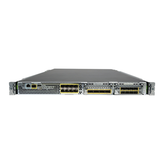
The following figure shows the Firepower 4100 series security appliance.
Features, on page 1
Deployment Options, on page 5
Package Contents, on page 5
Serial Number Location, on page 6
Front Panel, on page 8
Front Panel LEDs, on page 9
Rear Panel, on page 10
Network Modules, on page 11
Hardware Bypass Network Modules, on page 16
Power Supply Modules, on page 23
Fan Modules, on page 25
Supported SFP/SFP+ and QSFP Transceivers, on page 26
Hardware Specifications, on page 29
Product ID Numbers, on page 31
Power Cord Specifications, on page 34
for a list of the product IDs (PIDs) associated with the 4100 series.
Product ID Numbers,
Cisco Firepower 4100/9300 FXOS
Overview
1
Advertisement
Table of Contents

Related Manuals for Cisco Firepower 4100 Series


Summary of Contents for Cisco Firepower 4100 Series
-
Page 1: Table Of Contents
Power Cord Specifications, on page 34 Features The Cisco Firepower 4100 series security appliance is a standalone modular security services platform. It is capable of running multiple security services simultaneously and so is targeted at the data center as a multiservice platform. - Page 2 Overview Features Figure 1: Firepower 4100 Series The following table lists the features for the Firepower 4100 series. Table 1: Firepower 4100 Series Features Feature 4110 4120 4140 4150 Security standards • Common Criteria certification (CC) for the Network Device Collaborative certifications Protection Profile (NDcPPv2.2E), VPN Gateway Module (VPNGW_MOD_v1.1),...
-
Page 3: Features
Overview Features Feature 4110 4120 4140 4150 Airflow Front to rear Cold aisle to hot aisle Single 18-core Single 22-core Processor Single 12-core Memory 64-GB DDR4 128-GB DDR4 256-GB DDR4 256-GB DDR4 DRAM DRAM DRAM DRAM Maximum number of interfaces With two 8-port network modules installed Management port One Gigabit Ethernet... - Page 4 Overview Features Feature 4110 4120 4140 4150 Supported network • 8-port 10-Gigabit Ethernet SFP+ modules • 4-port 40-Gigabit Ethernet QSFP+ • 8-port 1-Gigabit Ethernet copper with hardware bypass • 2-port 40-Gigabit Ethernet QSFP+ (built-in) with hardware bypass • 6-port 1-Gigabit Ethernet SX fiber SFP (built-in) with hardware bypass •...
-
Page 5: Deployment Options
Overview Deployment Options Deployment Options Here are some examples of how you can deploy the Firepower 4100: • In a data center using NGFW and ASA • At the core/aggregation layer of a 3-tier data center in a high availability configuration •... -
Page 6: Serial Number Location
QR code and URL pointing to the Getting Started Guide. Serial Number Location The serial number for the Firepower 4100 series chassis is located on the pullout asset card on the front panel. Overview... - Page 7 Overview Serial Number Location Figure 3: Serial Number on the 4100 Chassis You can also view additional model information on the compliance label located on the bottom of the chassis. Figure 4: Compliance Label on the 4100 Chassis Overview...
-
Page 8: Front Panel
Overview Front Panel Front Panel The following figure shows the front panel of the Firepower 4100. Figure 5: Firepower 4100 Front Panel RJ-45 console port Gigabit Ethernet management port USB 2.0 Type A port Eight fixed SFP+ (1-Gb/10-Gb) ports (in network module slot 1) Ethernet 1/1 through 1/8 labeled top to bottom, left to right... -
Page 9: Front Panel Leds
• Security module log files • Platform bundle image upload using download image usbA: The USB Type A port does not support Cisco Secure Package (CSP) image upload. Network Ports The Firepower 4100 chassis has eight fixed ports that require 1-Gb/10-Gb SFP/SFP+ transceivers (fiber or copper). -
Page 10: Rear Panel
Overview Rear Panel Management Health (SYS) • Off—No connection or port is not in use. • Off—System is not booting yet. • Amber—No link or network failure. • Green, flashing—Power-up diagnostics are complete and system is booting up. • Green—Link up. •... - Page 11 Overview Network Modules Figure 7: Firepower 4100 Rear Panel Power on/off switch Power supply module 1 Power supply module 2 Fan module 1 Fan module 2 Fan module 3 Fan module 4 Fan module 5 Fan module 6 Location for the two-post grounding lug The two-post grounding lug is Note included in the accessory kit.
-
Page 12: Network Modules
Make sure you have the correct firmware package and software version installed to support this network module. For instructions on how to verify your firmware package version and to upgrade the firmware if necessary, see the Cisco Firepower 4100/9300 FXOS Firmware Upgrade Guide. See Cisco Firepower 4100/9300 FXOS Compatibility for the software compatibility matrix. - Page 13 Make sure you have the correct firmware package and software version installed to support this network module. For instructions on how to verify your firmware package version and to upgrade the firmware if necessary, see the Cisco Firepower 4100/9300 FXOS Firmware Upgrade Guide. See Cisco Firepower 4100/9300 FXOS Compatibility for the software compatibility matrix.
- Page 14 Make sure you have the correct firmware package and software version installed to support this network module. For instructions on how to verify your firmware package version and to upgrade the firmware if necessary, see the Cisco Firepower 4100/9300 FXOS Firmware Upgrade Guide. See Cisco Firepower 4100/9300 FXOS Compatibility for the software compatibility matrix.
- Page 15 Overview 100-Gb Network Module (Four Ports, Single Wide) Figure 10: FPR4K-NM-2X100G Power LED Network activity LEDs • Off—No connection or port is not in use. • Amber—No link or network failure. • Green—Link up. • Green, flashing—Network activity. Network activity LEDs Ethernet X/1 •...
- Page 16 Make sure you have the correct firmware package and software version installed to support this network module. For instructions on how to verify your firmware package version and to upgrade the firmware if necessary, see the Cisco Firepower 4100/9300 FXOS Firmware Upgrade Guide. See Cisco Firepower 4100/9300 FXOS Compatibility for the software compatibility matrix.
- Page 17 Overview Hardware Bypass Network Modules Hardware bypass is supported only on a fixed set of ports. You can pair Port 1 with Port 2, Port 3 with Port 4, but you cannot pair Port 1 with Port 4 for example. Note When the appliance switches from normal operation to hardware bypass or from hardware bypass back to normal operation, traffic may be interrupted for several seconds.
- Page 18 Make sure you have the correct firmware package and software version installed to support this network module. For instructions on how to verify your firmware package version and to upgrade the firmware if necessary, see the Cisco Firepower 4100/9300 FXOS Firmware Upgrade Guide. See Cisco Firepower 4100/9300 FXOS Compatibility for the software compatibility matrix.
- Page 19 Make sure you have the correct firmware package and software version installed to support this network module. For instructions on how to verify your firmware package version and to upgrade the firmware if necessary, see the Cisco Firepower 4100/9300 FXOS Firmware Upgrade Guide. See Cisco Firepower 4100/9300 FXOS Compatibility for the software compatibility matrix.
- Page 20 50 m cable distance Note See the Cisco 40GBASE QSFP Modules Data Sheet for specifications of the QSFP for the 40-Gb BASE-SR-4. We recommend the following Cisco OM3 MTP/MPO cables. Table 3: Cisco Cables Cisco Part Number Cable Length CAB-ETH-40G-5M...
- Page 21 Overview 1-Gb SX/10-Gb SR/10-Gb LR Network Module with Hardware Bypass Figure 14: FPR4K-NM-6X1SX-F, FPR4K-NM-6X10SR-F, FPR4K-NM-6X10LR-F Captive screw/handle Six network activity LEDs: • Amber—No connection, or port is not in use, or no link or network failure. • Green—Link up, no network activity. •...
- Page 22 Overview 1-Gb SX/10-Gb SR/10-Gb LR Network Module with Hardware Bypass Core diameter (microns) Modal bandwidth Cable distance (MHz/km) Half the Note distance specified by the IEEE standard. Cable and operating 62.5 160 (FDDI) 110 m distance 62.5 200 (OM1) 137 m 250 m 500 (OM2) 275 m...
- Page 23 Overview Power Supply Modules Core diameter (microns) Modal bandwidth Cable distance (MHz/km) Half the Note distance specified by the IEEE standard. Cable and operating G.652 Single mode 5 km distance Power Supply Modules The Firepower 4100 supports two AC or DC power supply modules so that dual power supply redundancy protection is available.
- Page 24 Overview Power Supply Modules Maximum output power 1100 W Frequency 50 to 60 Hz Redundancy 1+1 redundant Efficiency at 50% load DC Power Supply The power supplies can supply up to 950 W of power across the input voltage range. The load is shared when both power supply modules are plugged in and running at the same time.
- Page 25 Overview Fan Modules Table 9: Power Supply Module LEDs Amber LED (Fail Green LED (OK Status) Status) No power to all power supplies Power supply module failure Includes overvoltage, overcurrent, overtemperature, and fan failure Power supply module warning events 1 Hz flashing Power supply continues to operate.
- Page 26 Overview Supported SFP/SFP+ and QSFP Transceivers Figure 16: Fan LED Two-color LED The fan module has one two-color LED, which is located on the upper left corner of the fan. • Amber—Fan failure. • Green—Fan running normally. It may take up to one minute for the LED status to turn green after power is on.
- Page 27 Caution For some earlier production Firepower 4100 chassis, you may experience difficulty using the GLC-TE SFP on the management port or fixed ports. Contact Cisco TAC for support if you encounter problems with the GLC-TE SFP. The following table lists the Cisco supported transceivers.
- Page 28 Overview Supported SFP/SFP+ and QSFP Transceivers 1 Gb 1G-SX GLC-SX-MMD 1G-LH/LX GLC-LH-SMD 1G-EX GLC-EX-SMD 1G-ZX GLC-ZX-SMD 1G 1000Base-T GLC-T 1G 1000Base-T GLC-TE 10 Gb 10G-SR SFP-10G-SR 10G-SR-S SFP-10G-SR-S 10G-LR SFP-10G-LR 10G-LR-S SFP-10G-LR-S 10G-LRM SFP-10G-LRM 10G-ER SFP-10G-ER 10G-ER-S SFP-10G-ER-S 10G-ZR-S SFP-10G-ZR-S 10G Cu, 1m SFP-H10GB-CU1M 10G Cu, 1.5m...
- Page 29 Overview Hardware Specifications 10G AOC, 10m SFP-10GAOC10M 40 Gb 40G-SR4 QSFP-40G-SR4 40G-SR4-S QSFP-40G-SR4-S 40G-CSR4 QSFP-40G-CSR4 40G-SR-BD QSFP-40G-SR-BD 40GE-LR4 QSFP-40GE-LR4 40GE-LR4-S QSFP-40GE-LR4-S 40G-LR4L WSP-Q40GLR4L 40G-CU, 1M, 3M, 5M QSFP-H40G-CU 40G-4X10G-CU, 1M, 3M, 5M QSFP-4SFP10G-CU 40G-CU-A, 7M, 10M QSFP-H40G-ACU 40G-4X10G-CU-A, 7M, 10M QSFP-4X10G-AC 40G-AOC, 1M, 2M, 3M, 5M, 7M, 10M, 15M QSFP-H40G-AOC...
- Page 30 Overview Hardware Specifications Specification 4110 4120 4140 4150 100 GB 200 GB The storage SSD must be The storage SSD must be Note Note installed in slot 1. Slot 2 is installed in slot 1. Slot 2 is reserved for the optional MSP reserved for the optional MSP SSD.
- Page 31 0 to 13,000 ft (3962 Product ID Numbers The following table lists the PIDs associated with the Firepower 4100 series. All of the PIDs in the table are field-replaceable. If you need to get a return material authorization (RMA) for any component, see...
- Page 32 Overview Product ID Numbers Table 12: Firepower 4100 Series PIDs Description FPR4110-AMP-K9 Cisco Firepower 4110 AMP appliance, 1 RU, two network module bays FPR4110-ASA-K9 Cisco Firepower 4110 ASA appliance, 1 RU, two network module bays FPR4110-NGFW-K9 Cisco Firepower 4110 NGFW appliance, 1 RU, two...
- Page 33 Overview Product ID Numbers Description FPR4K-ACC-KIT= Firepower hardware accessory kit containing rack mounts and cables (spare) FPR4K-ASA-CAR License to add carrier security to ASA on the Firepower 4100 FPR4K-FAN FPR4K-FAN= Fan (spare) FPR4K-NM-2X40G-F 2-port 40-Gb SR hardware bypass network module FPR4K-NM-2X40G-F= 2-port 40-Gb SR hardware bypass network module (spare)
- Page 34 Overview Power Cord Specifications Description FPR4K-NM-BLANK= Network module blank slot cover (spare) FPR4K-PSU-BLANK Chassis power supply module blank slot cover FPR4K-PSU-BLANK= Chassis power supply module blank slot cover (spare) FPR4K-PWR-AC-1100 1100W AC power supply module FPR4K-PWR-AC-1100- 1100W AC power supply module (spare) FPR4K-PWR-DC-950 950W DC power supply module FPR4K-PWR-DC-950=...
- Page 35 Overview Power Cord Specifications Figure 18: Argentina CAB-9K10A-AR Plug: IRAM 2073 Cord set rating: 10 A, 250 V Connector: IEC 60320-C15 — Figure 19: Australia CAB-9K10A-AU Plug: A.S. 3112-2000 Cord set rating: 10 A, 250 V Connector: IEC 60320-C15 — Figure 20: Brazil CAB-250V-10A-BR Plug: EL223 (NBR 14136) Cord set rating: 10 A, 250 V...
- Page 36 Overview Power Cord Specifications Figure 21: Brazil PWR-CORD-G2A-BZ Plug: NBR 14136 Cord set rating: 10 A, 250 V Connector: IEC 60320-C13 — Figure 22: China CAB-9K10A-CH Plug: CCC GB2099.1, GB1002 Cord set rating: 10 A, 250 V Connector: IEC 60320-C15 —...
- Page 37 Overview Power Cord Specifications Figure 24: Europe CAB-AC-EUR Plug: CEE 7/7 Cord set rating: 10 A, 250 V Connector: IEC 60320-C15 — Figure 25: India CAB-250V-10A-ID Plug: IS 6538-1971 Cord set rating: 10 A, 250 V Connector: IEC 60320-C13 — Figure 26: Israel CAB-250V-10A-IS Plug: SI-32 Cord set rating: 10 A, 250 V...
- Page 38 Overview Power Cord Specifications Figure 27: Italy CAB-9K10A-IT Plug: CEI 23-16/VII Cord set rating: 10 A, 250 V Connector: IEC 60320-C15 — Figure 28: Korea CAB-9K10A-KOR Plug: CEE 7/7 Cord set rating: 10 A, 250 V Connector: IEC 60320-C19 — Figure 29: Japan CAB-L620P-C13-JPN Plug: NEMA L6-20P Cord set rating: 15 A, 250 V...
- Page 39 Overview Power Cord Specifications Figure 30: Japan CAB-TA-JP Plug: NEMA5-15P/JIS 8303 Cord set rating: 12 A, 125 V Connector: IEC 60320-C15 — Figure 31: North America CAB-TA-NA Plug: NEMA5-15P Cord set rating: 12 A, 125 V Connector: IEC 60320-C15 — Figure 32: Saudi Arabia ATA187PWRCORD-SAUD Plug: BS1363A/SS145 Cord set rating: 10 A, 250 V...
- Page 40 Overview Power Cord Specifications Figure 33: South Africa CAB-9K10A-SA Plug: SABS 164 Cord set rating: 10 A, 250 V Connector: IEC 60320-C15 — Figure 34: Switzerland CAB-9K10A-SW Plug: SEV 1011 Cord set rating: 10 A, 250 V Connector: IEC 60320-C15 —...
- Page 41 Overview Power Cord Specifications Figure 36: United Kingdom CP-PWR-CORD-UK Plug: BS1363A/SS145 Cord set rating: 10 A, 250 V Connector: IEC 60320-C13 — Overview...
- Page 42 Overview Power Cord Specifications Overview...