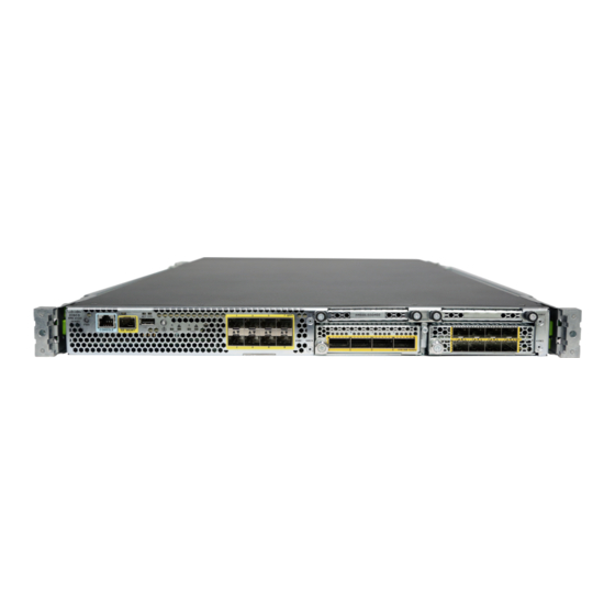
Cisco Firepower 4100 Series Maintenance And Upgrade Manual
Hide thumbs
Also See for Firepower 4100 Series:
- Command reference manual (421 pages) ,
- Hardware installation manual (82 pages) ,
- Manual (42 pages)
Table of Contents
Advertisement
Quick Links
Maintenance and Upgrade
•
•
•
•
•
•
Install the Network Module
Take note of the following warnings:
Warning
Statement 60 UL- and CSA-Certified Equipment Warning
This card is intended to be installed in UL- and CSA-certified equipment in the field by the user in the
manufacturer's defined operator access area. Check the equipment manufacturer to verify/confirm that your
equipment is suitable for user-installed application cards.
Warning
Statement 1029 Blank Faceplates and Cover Panels
Blank faceplates and cover panels serve three important functions: they prevent exposure to hazardous voltages
and currents inside the chassis; they contain electromagnetic interference (EMI) that might disrupt other
equipment; and they direct the flow of cooling air through the chassis. Do not operate the system unless all
cards, faceplates, front covers, and rear covers are in place.
Warning
Statement 1030 Equipment Installation
Only trained and qualified personnel should be allowed to install, replace, or service this equipment.
Install the Network Module, on page 1
Remove and Replace the Fan Module, on page 4
Remove and Replace the SSD, on page 5
Remove and Replace the Power Supply Module, on page 8
Connect the DC Power Supply Module, on page 10
Secure the Power Cord on the AC Power Supply Module, on page 16
Maintenance and Upgrade
1
Advertisement
Table of Contents

Related Manuals for Cisco Firepower 4100 Series


Summary of Contents for Cisco Firepower 4100 Series
- Page 1 Maintenance and Upgrade • Install the Network Module, on page 1 • Remove and Replace the Fan Module, on page 4 • Remove and Replace the SSD, on page 5 • Remove and Replace the Power Supply Module, on page 8 •...
- Page 2 Acknowledgment is necessary if you decommission and physically remove a network module and do not replace it, or if you replace it with another PID. See the "Acknowledging a Security Module/Engine” topic in the Security Module/Engine Management chapter in the Cisco FXOS Firepower Chassis Manager Configuration Guide.
- Page 3 Maintenance and Upgrade Install the Network Module c) Power on the chassis by moving the power switch to the ON position. The state for the new network module is OIR Failed d) To change the status of the network module to , reboot the chassis.
-
Page 4: Remove And Replace The Fan Module
Maintenance and Upgrade Remove and Replace the Fan Module If you install a network module that is a different PID than the original network module, the saved Note configuration is deleted and the default configuration is applied. You must enter the acknowledge command to confirm the network module PID change. -
Page 5: Remove And Replace The Ssd
Maintenance and Upgrade Remove and Replace the SSD Note The system supports operation with a single fan failure (N+1 fan redundancy), but do not run the system for an extended amount of time without all fan modules installed. Keep removal and replacement time at three minutes. - Page 6 Maintenance and Upgrade Remove and Replace the SSD Warning Statement 60 UL- and CSA-Certified Equipment Warning This card is intended to be installed in UL- and CSA-certified equipment in the field by the user in the manufacturer's defined operator access area. Check the equipment manufacturer to verify/confirm that your equipment is suitable for user-installed application cards.
- Page 7 Maintenance and Upgrade Remove and Replace the SSD the Advanced Malware Protection software feature. The MSP is supported beginning in FXOS 2.0.1. It is used as both storage and as the Malware application repository. RAID is not supported. Caution Do not switch the two SSDs. The storage SSD must be installed in slot 1. The optional MSP SSD must be installed in slot 2.
-
Page 8: Remove And Replace The Power Supply Module
Maintenance and Upgrade Remove and Replace the Power Supply Module Remove and Replace the Power Supply Module Take note of the following warnings: Warning Statement 1002 DC Power Supply When stranded wiring is required, use approved wiring terminations, such as closed-loop or spade-type with upturned lugs. - Page 9 Maintenance and Upgrade Remove and Replace the Power Supply Module Warning Statement 1030 Equipment Installation Only trained and qualified personnel should be allowed to install, replace, or service this equipment. Warning Statement 1040 Product Disposal Ultimate disposal of this product should be handled according to all national laws and regulations. Warning Statement 1045 Short-Circuit Protection This product requires short-circuit (overcurrent) protection to be provided as part of the building installation.
-
Page 10: Connect The Dc Power Supply Module
Maintenance and Upgrade Connect the DC Power Supply Module Figure 4: Remove the Power Supply Module If the slot is to remain empty, install a blank faceplate to ensure proper airflow and to keep dust out of the chassis; otherwise, install another power supply module. Step 4 To replace a power supply module, hold the power supply module with both hands and slide it into the power supply module bay. - Page 11 Maintenance and Upgrade Connect the DC Power Supply Module Warning Statement 1003 DC Power Disconnection Before performing any of the following procedures, ensure that power is removed from the DC circuit. Warning Statement 1005—Circuit Breaker This product relies on the building's installation for short-circuit (overcurrent) protection. Ensure that the protective device is rated not great than: AC power 120 V AC, 20 A (US), 240 V AC, 16 A (EU), DC power 60 V, 35 A.
- Page 12 Maintenance and Upgrade Connect the DC Power Supply Module Warning Statement 1040 Product Disposal Ultimate disposal of this product should be handled according to all national laws and regulations. Warning Statement 1045 Short-Circuit Protection This product requires short-circuit (overcurrent) protection to be provided as part of the building installation. Install only in accordance with national and local wiring regulations.
- Page 13 Maintenance and Upgrade Connect the DC Power Supply Module • 10-mm wrench or socket • Connectors and wire for the DC circuit or circuits Each DC input power cable is terminated at the PDU by a cable lug, as shown in the following figure. Note DC input power cables must be connected to the PDU terminal studs in the proper positive (+) and negative (–) polarity.
- Page 14 Maintenance and Upgrade Connect the DC Power Supply Module Figure 6: Remove the Plastic Cover Step 5 To prevent any contact with metal lead on the ground wire and the plastic cover, you must wrap the positive and negative lead cables with sleeving. Insulate the lug with shrink sleeving for each lead wire if using noninsulated crimp terminals. Sleeving is not required for insulated terminals.
- Page 15 Maintenance and Upgrade Connect the DC Power Supply Module Figure 8: Insert the Cables Step 8 Tighten the M5 screw with the captive washer to the recommended torque of 5 in-lbs for the positive stud and wire. Secure the wires coming in from the terminal block so that they cannot be disturbed by casual contact. Figure 9: Tighten the M5 Screws Step 9 Replace the terminal block plastic cover.
-
Page 16: Secure The Power Cord On The Ac Power Supply Module
Maintenance and Upgrade Secure the Power Cord on the AC Power Supply Module Figure 10: Replace the Plastic Cover Step 10 Set the DC disconnect switch in the circuit to ON. In a system with multiple power supplies, connect each power supply to a separate DC power source. - Page 17 Maintenance and Upgrade Secure the Power Cord on the AC Power Supply Module The black tie wrap is used with the Flextronics power supply module and the off-white tie wrap is used with the Artesyn power supply module. The black clamp works with both. See the figures below. Step 1 Attach the clamp to the tie wrap by holding the clamp with the loop side on the bottom and sliding the tie wrap through the box-shaped channel above the clamp (see the following figure).
- Page 18 Maintenance and Upgrade Secure the Power Cord on the AC Power Supply Module Figure 12: Flextronics Power Supply Module Flextronics tie wrap Hexagonal hole Figure 13: Artesyn Power Supply Module Artesyn tie wrap Hexagonal hole Step 3 Secure the clamp: a) Plug in the power supply power cord and wrap the clamp around the over mold portion of the power cord.
- Page 19 Maintenance and Upgrade Secure the Power Cord on the AC Power Supply Module Figure 14: Clamp on Over Mold of Power Cord Mold portion of the power cord Clamp ends Step 4 If you need to remove the power cord, push the release tab on the clamp to force the annular clamp teeth to disengage and the clamp opens up.
- Page 20 Maintenance and Upgrade Secure the Power Cord on the AC Power Supply Module Maintenance and Upgrade...