Table of Contents
Advertisement
Quick Links
Advertisement
Table of Contents

Summary of Contents for Mitsubishi Electric RD55UP12-V
- Page 1 IoT Gateway IBHsoftec OPC UA Server function...
-
Page 2: Table Of Contents
3.1 Software used ....................8 3.2 Prepare SD card ....................8 3.3 Prepare hardware ..................... 9 3.4 Set IP addresses for RD55UP12-V IBH ............9 3.5 IoT Gateway OPC UA Server Setup ............... 10 3.5.1 Launch web interface ......................10 3.5.2 Activate licence code ...................... - Page 3 9.2 Access to controllers (CPUs / devices) that are connected to the ports of the control level......................66 9.2.1 iQ-R CPU ..........................66 9.2.2 Robot ............................ 67 9.2.3 GOT ............................69 _________________________________________________________________________ Document: Quickstart_IoTGateway_EN Mitsubishi Electric Europe B.V. Rev: 001G Date: 01/02/2022...
-
Page 4: Relevant Manuals
CW Workbench/CW-Sime-Manual GX Works3 Operating Manual System configurations, parameter settings, and operation [SH-081215ENG] methods for the online function in GX Works3 GT Designer3 (GOT2000) Screen Design Manual [SH-081220ENG] _________________________________________________________________________ Document: Quickstart_IoTGateway_EN Mitsubishi Electric Europe B.V. Rev: 001G Date: 01/02/2022... -
Page 5: Overview
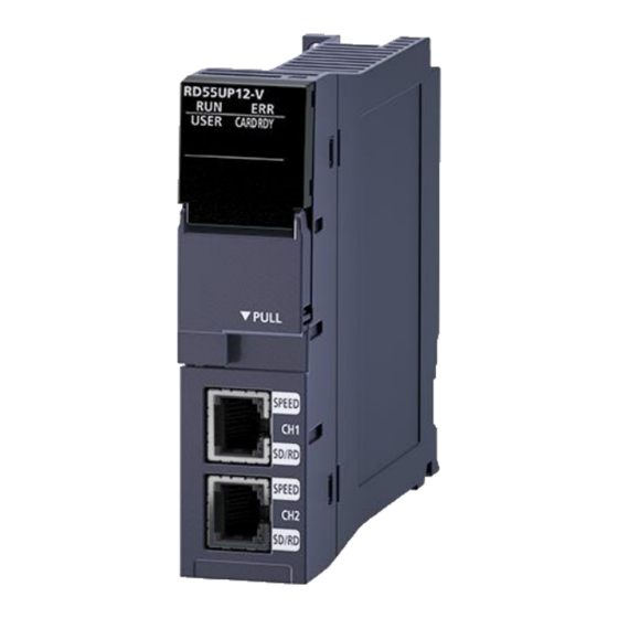
One solution for reading process data from Mitsubishi Electric controllers and robots that do not have an OPC interface as standard is the RD55UP12-V module with installed IBH Link UA software, called IoT Gateway . This solution is a server/client module. The OPC client function also enables OPC servers to exchange data with each other. -
Page 6: Security
Another security level of OPC UA is the exchange of certificates. Communication is only possible when both server and client have been assigned a valid certificate by the respective partner. _________________________________________________________________________ Document: Quickstart_IoTGateway_EN Mitsubishi Electric Europe B.V. Rev: 001G Date: 01/02/2022... -
Page 7: Commissioning
3 Commissioning Each RD55UP12-V can be started as an IoT Gateway module. For this purpose, a corresponding image must be written to an SD card. The image file contains the Linux operating system and the corresponding programme from IBH for the OPC UA server function. -
Page 8: Software Used
In addition, a web browser must be installed on the PC. If you have received an already configured IoT Gateway from Mitsubishi Electric, the following setup chapters 3.2 to 3.5 are not required. For your security, we recommend that you create a backup copy of the inserted SD card, as described in Chapter 3.6. -
Page 9: Prepare Hardware
3.3 Prepare hardware Unpack the selected iQ-R hardware, mount it to the base rack and connect it as instructed (refer to Mitsubishi Electric hardware manuals). The control unit can now be switched on. 3.4 Set IP addresses for RD55UP12-V IBH First, you have to create a project in GW-Works3 that matches the hardware you have plugged in. -
Page 10: Iot Gateway Opc Ua Server Setup
In the following example, the PC is connected via the process level, only "192.168.0.3" is entered in the browser. The login screen is displayed. For a new system, the default user name and password are both "admin". _________________________________________________________________________ Document: Quickstart_IoTGateway_EN Mitsubishi Electric Europe B.V. Rev: 001G Date: 01/02/2022... -
Page 11: Activate Licence Code
After you have received the license file from IBHsoftec matching the module serial number and MAC addresses, this must be imported into the module once. To do this, select the "System" menu in the configuration interface. _________________________________________________________________________ Document: Quickstart_IoTGateway_EN Mitsubishi Electric Europe B.V. Rev: 001G Date: 01/02/2022... -
Page 12: Backup / Restore Of Sd Card
After all the necessary configurations have been made and the project functions have also been parameterized, a backup copy can be created from the SD card using the "DDWIN" software. This backup can only be used in the RD55UP12-V module with the hardware ID for which the IoT Gateway license was created. -
Page 13: Restore The Sd Card
3.6.2 Restore the SD card To load the image onto a new SD card, the "DDWIN.EXE" program must be run as an administrator Then insert a new SD card into the PC _________________________________________________________________________ Document: Quickstart_IoTGateway_EN Mitsubishi Electric Europe B.V. Rev: 001G Date: 01/02/2022... -
Page 14: Opc Ua Server Function
3. Select „<<Restore<<“ After the message "Writing has completed ..." the SD card can be plugged into the corresponding RD55UP12-V module and then the controller can be switched on. 4 OPC UA server function This chapter explains how to connect the IoT Gateway to controllers and make their global variables available as OPC UA tags for clients. -
Page 15: Export Global Variables
4.1.2 Export global variables _________________________________________________________________________ Document: Quickstart_IoTGateway_EN Mitsubishi Electric Europe B.V. Rev: 001G Date: 01/02/2022... -
Page 16: Add A Controller Via Web Interface
4.1.3 Add a controller via web interface Insert station 4.1.4 Insert CPU _________________________________________________________________________ Document: Quickstart_IoTGateway_EN Mitsubishi Electric Europe B.V. Rev: 001G Date: 01/02/2022... -
Page 17: Import Xml File
The European version of GX Works 3 offers the function to export the project as an XML file. → The file created by this function can be uploaded to the IoT Gateway web server. _________________________________________________________________________ Document: Quickstart_IoTGateway_EN Mitsubishi Electric Europe B.V. Rev: 001G Date: 01/02/2022... - Page 18 Now all global variables of the imported project are automatically available in the OPC UA Server. _________________________________________________________________________ Document: Quickstart_IoTGateway_EN Mitsubishi Electric Europe B.V. Rev: 001G Date: 01/02/2022...
-
Page 19: Connect External Opc Ua Client
4.1.6 Connect external OPC UA Client The free UaExpert is used here as a test client. https://www.unified-automation.com/de/downloads/opc-ua-clients.html _________________________________________________________________________ Document: Quickstart_IoTGateway_EN Mitsubishi Electric Europe B.V. Rev: 001G Date: 01/02/2022... - Page 20 _________________________________________________________________________ Document: Quickstart_IoTGateway_EN Mitsubishi Electric Europe B.V. Rev: 001G Date: 01/02/2022...
- Page 21 _________________________________________________________________________ Document: Quickstart_IoTGateway_EN Mitsubishi Electric Europe B.V. Rev: 001G Date: 01/02/2022...
-
Page 22: Robot
4.2 Robot 4.2.1 Communication settings RT Toolbox3 Project setting Parameter setting _________________________________________________________________________ Document: Quickstart_IoTGateway_EN Mitsubishi Electric Europe B.V. Rev: 001G Date: 01/02/2022... -
Page 23: Insert Robot Via Web Interface
If the Ethernet connection is OK, the robot model and the number of axes are entered automatically by pressing "Read type". Then press "OK". After a few seconds, the web interface will again show "OPC server running" in a green box. _________________________________________________________________________ Document: Quickstart_IoTGateway_EN Mitsubishi Electric Europe B.V. Rev: 001G Date: 01/02/2022... -
Page 24: Display In The External Opc Ua Client
As soon as the server is running again, it can be selected in the Client Tool (here UaExpert) and you have access to all OPC UA tags from the robot that are defined in the OPC UA Companion Specification Part1. _________________________________________________________________________ Document: Quickstart_IoTGateway_EN Mitsubishi Electric Europe B.V. Rev: 001G Date: 01/02/2022... -
Page 25: Add Additional Outputs
Depending on the browser, the file is then automatically saved in the "Download" folder or you are asked for a destination folder. Edit XML file Open the downloaded file with a text editor and scroll it to the desired "Inputs" or "Outputs" section. _________________________________________________________________________ Document: Quickstart_IoTGateway_EN Mitsubishi Electric Europe B.V. Rev: 001G Date: 01/02/2022... - Page 26 M_Outw(10224): Once all the desired entries have been made, the file is saved. Load XML file The modified file can now be loaded again in the RD55-IBH web server: _________________________________________________________________________ Document: Quickstart_IoTGateway_EN Mitsubishi Electric Europe B.V. Rev: 001G Date: 01/02/2022...
-
Page 27: Inverter
SLMP is different. This quick start guide only provides an overview using examples; details about the individual parameters and registers can be found in the corresponding manuals for the Mitsubishi Electric Inverter. What they have in common, however, are the settings of the inverter parameters for Ethernet communication. - Page 28 The inverter is then added as "New PLC station ...". The name can be freely selected, the Ethernet address must correspond to the inputs of the inverter parameters. Now a "New CPU ..." has to be added _________________________________________________________________________ Document: Quickstart_IoTGateway_EN Mitsubishi Electric Europe B.V. Rev: 001G Date: 01/02/2022...
- Page 29 You only have to enter a freely selectable name and press "OK" The variables are entered in a structure that has yet to be created. _________________________________________________________________________ Document: Quickstart_IoTGateway_EN Mitsubishi Electric Europe B.V. Rev: 001G Date: 01/02/2022...
-
Page 30: A800/F800
With the A800 / F800 inverters, the status can be monitored and controlled with certain special registers. In order for this to be possible, the PLC function of the inverter must be activated _________________________________________________________________________ Document: Quickstart_IoTGateway_EN Mitsubishi Electric Europe B.V. Rev: 001G Date: 01/02/2022... - Page 31 Below are a few examples; the complete list of special registers can be found in the relevant manual. Example: error history Entering the variable Example 1: output frequency _________________________________________________________________________ Document: Quickstart_IoTGateway_EN Mitsubishi Electric Europe B.V. Rev: 001G Date: 01/02/2022...
- Page 32 Right-click on the Mitsubishi station and then select "Write Mitsubishi configuration to server ..." to transfer the changes to the IoT gateway. Further parameters can be added: _________________________________________________________________________ Document: Quickstart_IoTGateway_EN Mitsubishi Electric Europe B.V. Rev: 001G Date: 01/02/2022...
- Page 33 <Variable name="RunningSpeed" address="SD1153" type="Int16"/> <Variable name="MotorTorque" address="SD1154" type="Int16"/> <Variable name="ErrorHistory_01" address="SD1136" type="Int16"/> <Variable name="ErrorHistory_02" address="SD1137" type="Int16"/> <Variable name="ErrorHistory_03" address="SD1138" type="Int16"/> <Variable name="ErrorHistory_04" address="SD1139" type="Int16"/> </struct> </GlobalVars> </CPU> </Device> </Objects> _________________________________________________________________________ Document: Quickstart_IoTGateway_EN Mitsubishi Electric Europe B.V. Rev: 001G Date: 01/02/2022...
-
Page 34: E800-E
With the E800 inverters, the status can be monitored and controlled with certain special SLMP Link registers. In order for this to be possible, the PLC function of the inverter must be activated Link Register Parameter Inverter Status _________________________________________________________________________ Document: Quickstart_IoTGateway_EN Mitsubishi Electric Europe B.V. Rev: 001G Date: 01/02/2022... - Page 35 Preventive maintenance data Model information monitor Serial number Details on the parameters can be found in the E800 manual “Instruction Manual (Communication)”. Entering the variable Example 1: output frequency _________________________________________________________________________ Document: Quickstart_IoTGateway_EN Mitsubishi Electric Europe B.V. Rev: 001G Date: 01/02/2022...
- Page 36 The configuration generated in the OPCUAEdit tool can be exported as an XML file in the IoT Gateway web server. This generated XML file can then be edited in any text editor and then transferred back to the IoT Gateway using "Load XML". _________________________________________________________________________ Document: Quickstart_IoTGateway_EN Mitsubishi Electric Europe B.V. Rev: 001G Date: 01/02/2022...
-
Page 37: Diagnostics
5.1 Controller diagnostics The configured connections and their status (error-free / faulty) are displayed. 5.2 Client diagnostics The current states of the configured OPC client connections (error-free / faulty) are displayed. _________________________________________________________________________ Document: Quickstart_IoTGateway_EN Mitsubishi Electric Europe B.V. Rev: 001G Date: 01/02/2022... -
Page 38: Network Diagnostics
If the Wireshark diagnostic software is installed on the PC, a very extensive network analysis can be carried out. After selecting the ethernet interface and the port to be checked press the “Start trace” button. _________________________________________________________________________ Document: Quickstart_IoTGateway_EN Mitsubishi Electric Europe B.V. Rev: 001G Date: 01/02/2022... - Page 39 Since the evaluation of Wireshark-Trace requires some specialist knowledge, this diagnosis should be carried out in the event of a malfunction using the IBHsoftec hotline. _________________________________________________________________________ Document: Quickstart_IoTGateway_EN Mitsubishi Electric Europe B.V. Rev: 001G Date: 01/02/2022...
-
Page 40: System Log
Buttons are provided to display the log file in an editor or to save it as a text file or to delete it. In the event of a malfunction, an analysis can be carried out using the IBHsoftec hotline. _________________________________________________________________________ Document: Quickstart_IoTGateway_EN Mitsubishi Electric Europe B.V. Rev: 001G Date: 01/02/2022... - Page 41 All the background operations of the IoT Gateway can be made visible by activating the “Enable Trace” checkbox. After the event that should be evaluated has occurred, the current recorded data can be downloaded and opened in a text editor. _________________________________________________________________________ Document: Quickstart_IoTGateway_EN Mitsubishi Electric Europe B.V. Rev: 001G Date: 01/02/2022...
- Page 42 To evaluate this information requires some specialist knowledge, this diagnosis should be carried out in the event of a malfunction using the IBHsoftec hotline. _________________________________________________________________________ Document: Quickstart_IoTGateway_EN Mitsubishi Electric Europe B.V. Rev: 001G Date: 01/02/2022...
-
Page 43: Opc Client Function Example
The following structure serves as an example: On the iQ-R rack there is an R04 CPU (192.168.0.38), an IoT Gateway (192.168.0.3) and an RD81OPC96 module (192.168.0.5). Both OPC UA servers on RD55 and RD81 are active. RD55UP12-V OPC Server Setting RD81OPC96 Server Setting _________________________________________________________________________ Document: Quickstart_IoTGateway_EN Mitsubishi Electric Europe B.V. - Page 44 _________________________________________________________________________ Document: Quickstart_IoTGateway_EN Mitsubishi Electric Europe B.V. Rev: 001G Date: 01/02/2022...
-
Page 45: Modbus
The new empty MODBUS configuration is displayed. Clicking on the icon opens the window for entering the MODBUS server connection data: → Only the connection name (freely selectable) and the connection data are required here. _________________________________________________________________________ Document: Quickstart_IoTGateway_EN Mitsubishi Electric Europe B.V. Rev: 001G Date: 01/02/2022... -
Page 46: Add Variables
After clicking on "OK" the new MODBUS connection is displayed. 7.2 Add Variables In the next window, which is opened by right-clicking on the desired connection, select "New variable..." _________________________________________________________________________ Document: Quickstart_IoTGateway_EN Mitsubishi Electric Europe B.V. Rev: 001G Date: 01/02/2022... - Page 47 The address range of the holding registers is between 0 and 999 The first variable in the example is of type INT16, the data from holding register 100 is read/written _________________________________________________________________________ Document: Quickstart_IoTGateway_EN Mitsubishi Electric Europe B.V. Rev: 001G Date: 01/02/2022...
-
Page 48: Usage Of Modbus-Data
After the transfer to the IoT Gateway, the new MODBUS connection is visible in the web interface. This means that the data is available to every OPC UA client, … _________________________________________________________________________ Document: Quickstart_IoTGateway_EN Mitsubishi Electric Europe B.V. Rev: 001G Date: 01/02/2022... - Page 49 … and can also be sent to the IT world via MQTT _________________________________________________________________________ Document: Quickstart_IoTGateway_EN Mitsubishi Electric Europe B.V. Rev: 001G Date: 01/02/2022...
-
Page 50: Mqtt Settings
In addition, the MQTT message format can be selected under "Message template". With "Default" the simple JSON format is used. If you want to communicate Iconics format, you can select it here accordingly. _________________________________________________________________________ Document: Quickstart_IoTGateway_EN Mitsubishi Electric Europe B.V. Rev: 001G Date: 01/02/2022... -
Page 51: Publish Of Values (Send Data To Broker)
1. Create a new topic 2. Link the topic with data 8.2.1 Create Topic Open the newly created “SampleBroker” by pressing, then right-click on “Publish” to open the menu and select “New topic” _________________________________________________________________________ Document: Quickstart_IoTGateway_EN Mitsubishi Electric Europe B.V. Rev: 001G Date: 01/02/2022... - Page 52 In this example, the selected variable is checked for changes every 1000ms and "Publish" is started if the condition is met. The variable to be checked can be selected from the OPC UA server (UA nodes). _________________________________________________________________________ Document: Quickstart_IoTGateway_EN Mitsubishi Electric Europe B.V. Rev: 001G Date: 01/02/2022...
-
Page 53: Create New Variable (Data To Be Sent)
The selected data are then displayed in the active topic in the editor Send the new setting to the IoT gateway and after the transfer has taken place, check whether the IoT gateway is connected to the broker. _________________________________________________________________________ Document: Quickstart_IoTGateway_EN Mitsubishi Electric Europe B.V. Rev: 001G Date: 01/02/2022... -
Page 54: Check Data In Broker
(Counter01 to Counter03) to "0". 8.3.1 Create Topic Open SampleBroker ”by pressing, then right-click on“ Subscribe ”and select“ New topic ”. Enter a name for the new topic and confirm with “OK”. _________________________________________________________________________ Document: Quickstart_IoTGateway_EN Mitsubishi Electric Europe B.V. Rev: 001G Date: 01/02/2022... -
Page 55: Create New Variable
8.3.2 Create new variable Select the new topic, right-click to open the menu and press “Select variables…” Select the required data in the next window and confirm with “OK” _________________________________________________________________________ Document: Quickstart_IoTGateway_EN Mitsubishi Electric Europe B.V. Rev: 001G Date: 01/02/2022... -
Page 56: Function Test Of "Subscribe
In the Sunscribe topic, the IoT Gateway expects a string in JSON format from the publisher, which must look like this: {"Counter01":0,"Counter02":0,"Counter03":0} Befor “Publish” on Broker-side Short after “Publish” on Broker-side _________________________________________________________________________ Document: Quickstart_IoTGateway_EN Mitsubishi Electric Europe B.V. Rev: 001G Date: 01/02/2022... -
Page 57: Teamviewer Iot Connection
A TeamViewer software is pre-installed in the This offers the possibility of accessing almost all Mitsubishi Electric automation components at any time and from anywhere. Complex modem solutions or the use of a PC on site are a thing of the past. -
Page 58: Pc Preparations - Connected To The Ethernet Port Of The Control Level
A TeamViewer account with an appropriate licence must be ready to activate. If not already present, a new group must be added under Computers and Contacts after logging in. _________________________________________________________________________ Document: Quickstart_IoTGateway_EN Mitsubishi Electric Europe B.V. Rev: 001G Date: 01/02/2022... -
Page 59: Ibhnet Iot Setup
If necessary, change the properties of the taskbar to display the icon. If the icon shows a stopped service, start the service. 9.1.3 TeamViewer IoT Management Console With the link https://teamviewer-iot.com/en/ _________________________________________________________________________ Document: Quickstart_IoTGateway_EN Mitsubishi Electric Europe B.V. Rev: 001G Date: 01/02/2022... - Page 60 TeamViewer Internet of Things login page and log in. After logging into the TeamViewer IoT Management Console, open the Assignment token dialogue box. Click on the Copy symbol to copy the assignment token to the Windows clipboard. _________________________________________________________________________ Document: Quickstart_IoTGateway_EN Mitsubishi Electric Europe B.V. Rev: 001G Date: 01/02/2022...
- Page 61 Automatically switch on TeamViewer must be set. Now you can click on Reassign To apply the settings, the TeamViewer IoT End User Licence Agreement must be accepted by clicking the Agree button. _________________________________________________________________________ Document: Quickstart_IoTGateway_EN Mitsubishi Electric Europe B.V. Rev: 001G Date: 01/02/2022...
- Page 62 Insert the TeamViewer ID number in the field with the same name. The display name is transferred to the TeamViewer account. This name can be used to establish a connection to the IBH Link UA via the internet. _________________________________________________________________________ Document: Quickstart_IoTGateway_EN Mitsubishi Electric Europe B.V. Rev: 001G Date: 01/02/2022...
-
Page 63: Connection Setup
From any PC, a connection can be established via the Internet to the IoT Gateway and thus to the PLC controllers and other devices connected to the control level ports. _________________________________________________________________________ Document: Quickstart_IoTGateway_EN Mitsubishi Electric Europe B.V. Rev: 001G Date: 01/02/2022... - Page 64 Right-click on the IBHNet-IoT Tray icon to open the context menu. The devices registered with the TeamViewer account are listed in the upper section of the context menu. Click on the desired device (RD55_IBH) to establish the connection. _________________________________________________________________________ Document: Quickstart_IoTGateway_EN Mitsubishi Electric Europe B.V. Rev: 001G Date: 01/02/2022...
- Page 65 During the TeamViewer start-up process, it can happen that no connection is established and error messages are displayed. These error messages are to be closed with Cancel. The start process must be restarted. _________________________________________________________________________ Document: Quickstart_IoTGateway_EN Mitsubishi Electric Europe B.V. Rev: 001G Date: 01/02/2022...
-
Page 66: Access To Controllers (Cpus / Devices) That Are Connected To The Ports Of The Control Level
(CPUs / devices) connected to the control level ports can be accessed with the corresponding software (programming system). 9.2 Access to controllers (CPUs / devices) that are connected to the ports of the control level. 9.2.1 iQ-R CPU _________________________________________________________________________ Document: Quickstart_IoTGateway_EN Mitsubishi Electric Europe B.V. Rev: 001G Date: 01/02/2022... -
Page 67: Robot
9.2.2 Robot Example: Connection with Q172DRCPU Hardware structure: Communication setting in the RT Toolbox 3: _________________________________________________________________________ Document: Quickstart_IoTGateway_EN Mitsubishi Electric Europe B.V. Rev: 001G Date: 01/02/2022... - Page 68 _________________________________________________________________________ Document: Quickstart_IoTGateway_EN Mitsubishi Electric Europe B.V. Rev: 001G Date: 01/02/2022...
-
Page 69: Got
9.2.3 GOT In the GT-Designer3, it is not necessary to select an IoT tunnel if one exists; entering the destination IP address of the GOT is sufficient: → _________________________________________________________________________ Document: Quickstart_IoTGateway_EN Mitsubishi Electric Europe B.V. Rev: 001G Date: 01/02/2022...