ABB Relion 670 Series Commissioning Manual
Hide thumbs
Also See for Relion 670 Series:
- Technical manual (1432 pages) ,
- Technical reference manual (1232 pages) ,
- Applications manual (944 pages)
Table of Contents
Advertisement
Quick Links
Advertisement
Table of Contents

Related Manuals for ABB Relion 670 Series


Summary of Contents for ABB Relion 670 Series
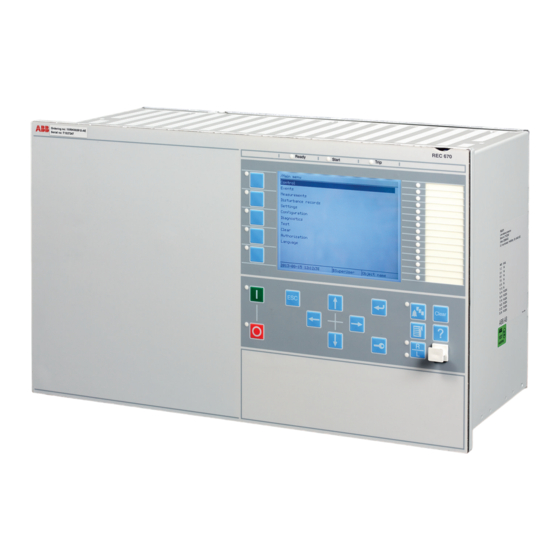
- Page 1 ® Relion 670 SERIES Bay control REC670 Version 2.2 IEC Commissioning manual...
- Page 3 Document ID: 1MRK 511 403-UEN Issued: June 2021 Revision: K Product version: 2.2 © 2017 - 2021 Hitachi Power Grids. All rights reserved...
- Page 4 Young (eay@cryptsoft.com) and Tim Hudson (tjh@cryptsoft.com). Trademarks ABB is a registered trademark of ABB Asea Brown Boveri Ltd. Manufactured by/for a Hitachi Power Grids company. All other brand or product names mentioned in this document may be trademarks or registered trademarks of their respective holders.
- Page 5 Disclaimer The data, examples and diagrams in this manual are included solely for the concept or product description and are not to be deemed as a statement of guaranteed properties. All persons responsible for applying the equipment addressed in this manual must satisfy themselves that each intended application is suitable and acceptable, including that any applicable safety or other operational requirements are complied with.
- Page 6 Conformity This product complies with the directive of the Council of the European Communities on the approximation of the laws of the Member States relating to electromagnetic compatibility (EMC Directive 2004/108/EC) and concerning electrical equipment for use within specified voltage limits (Low-voltage directive 2006/95/EC).
-
Page 7: Table Of Contents
1MRK 511 403-UEN Rev. K Table of contents Table of contents Section 1 Introduction....................11 This manual......................... 11 Intended audience....................... 11 Product documentation....................... 12 1.3.1 Product documentation set....................12 1.3.2 Document revision history....................13 1.3.3 Related documents......................14 Document symbols and conventions...................14 1.4.1 Symbols..........................14 1.4.2... - Page 8 Table of contents 1MRK 511 403-UEN Rev. K Section 5 Configuring the IED and changing settings..........49 Overview..........................49 Configuring analog CT inputs....................49 Supervision of input/output modules................... 50 Section 6 Establishing connection and verifying the SPA/IEC communication..51 Entering settings........................51 6.1.1 Entering SPA settings......................51 6.1.2 Entering IEC settings......................51 Verifying the communication....................
- Page 9 1MRK 511 403-UEN Rev. K Table of contents 10.7 Testing the protection functionality..................78 10.8 Forcing of binary input/output signals for testing..............78 10.8.1 Forcing concept.........................78 10.8.2 How to enable forcing......................79 10.8.2.1 Enable forcing by using LHMI..................79 10.8.2.2 Enable forcing using TESTMODE function block............79 10.8.3 How to change binary input/output signals using forcing..........
- Page 10 Table of contents 1MRK 511 403-UEN Rev. K 11.4.6.2 Completing the test...................... 97 11.4.7 Thermal overload protection, one time constant, Celsius/Fahrenheit LCPTTR/LFPTTR..97 11.4.7.1 Measuring the operate and time limit of set values............97 11.4.7.2 Completing the test...................... 98 11.4.8 Thermal overload protection, two time constants TRPTTR ..........98 11.4.8.1 Checking operate and reset values................98 11.4.8.2...
- Page 11 1MRK 511 403-UEN Rev. K Table of contents 11.4.16.2 Completing the test....................113 11.4.17 Voltage-restrained time overcurrent protection VRPVOC..........113 11.4.17.1 Function revision history.....................113 11.4.17.2 Verifying the settings....................114 11.4.17.3 Completing the test....................116 11.4.18 Average Power Transient Earth Fault Protection, APPTEF..........116 11.4.18.1 Verifying the signals and settings................
- Page 12 Table of contents 1MRK 511 403-UEN Rev. K 11.7.1.1 Verifying the settings....................142 11.7.1.2 Completing the test....................143 11.7.2 Overfrequency protection SAPTOF ................143 11.7.2.1 Verifying the settings....................143 11.7.2.2 Completing the test....................144 11.7.3 Rate-of-change frequency protection SAPFRC ............. 144 11.7.3.1 Verifying the settings....................
- Page 13 1MRK 511 403-UEN Rev. K Table of contents 11.10.1.3 Testing the energizing check..................160 11.10.1.4 Testing the voltage selection..................161 11.10.1.5 Completing the test....................163 11.10.2 Autorecloser for 1/2/3-phase operation SMBRREC ............163 11.10.2.1 Preparation of the verification ................... 165 11.10.2.2 Switching the auto recloser to On and Off On and Off ..........165 11.10.2.3 Verifying the auto recloser ..................166...
- Page 14 Table of contents 1MRK 511 403-UEN Rev. K 11.11.5 Current reversal and weak-end infeed logic for residual overcurrent protection ECRWPSCH ........................183 11.11.5.1 Testing the current reversal logic................184 11.11.5.2 Testing the weak-end infeed logic................184 11.11.5.3 Completing the test....................185 11.12 Logic..........................185 11.12.1...
- Page 15 1MRK 511 403-UEN Rev. K Table of contents 11.13.12 Function revision history....................198 11.13.13 Fault current and voltage monitoring function FLTMMXU ..........198 11.13.13.1 Verifying the settings....................198 11.13.13.2 Completing the test....................198 11.13.14 Fault locator LMBRFLO....................198 11.13.14.1 Function revision history.................... 199 11.13.14.2 Verifying the signals and settings................199 11.13.14.3...
- Page 16 Table of contents 1MRK 511 403-UEN Rev. K 14.1 Checking the self supervision signals................215 14.1.1 Checking the self supervision function................215 14.1.1.1 Determine the cause of an internal failure..............215 14.1.2 Self supervision HMI data....................215 14.1.2.1 General IED status.....................215 14.2 Fault tracing........................216 14.2.1...
-
Page 17: Introduction
1MRK 511 403-UEN Rev. K Section 1 Introduction Section 1 Introduction This manual GUID-AB423A30-13C2-46AF-B7FE-A73BB425EB5F v20 The commissioning manual contains instructions on how to commission the IED. The manual can also be used by system engineers and maintenance personnel for assistance during the testing phase. -
Page 18: Product Documentation
Section 1 1MRK 511 403-UEN Rev. K Introduction Product documentation 1.3.1 Product documentation set GUID-3AA69EA6-F1D8-47C6-A8E6-562F29C67172 v16 Engineering manual Installation manual Commissioning manual Operation manual Application manual Technical manual Communication protocol manual Cyber security deployment guideline IEC07000220-4-en.vsd IEC07000220 V4 EN-US Figure 1: The intended use of manuals throughout the product lifecycle The engineering manual contains instructions on how to engineer the IEDs using the various tools available within the PCM600 software. -
Page 19: Document Revision History
1MRK 511 403-UEN Rev. K Section 1 Introduction The application manual contains application descriptions and setting guidelines sorted per function. The manual can be used to find out when and for what purpose a typical protection function can be used. The manual can also provide assistance for calculating settings. The technical manual contains operation principle descriptions, and lists function blocks, logic diagrams, input and output signals, setting parameters and technical data, sorted per function. -
Page 20: Related Documents
Section 1 1MRK 511 403-UEN Rev. K Introduction 1.3.3 Related documents GUID-94E8A5CA-BE1B-45AF-81E7-5A41D34EE112 v8 Documents related to REC670 Document numbers Application manual 1MRK 511 401-UEN Commissioning manual 1MRK 511 403-UEN Product guide 1MRK 511 404-BEN Technical manual 1MRK 511 402-UEN Type test certificate 1MRK 511 404-TEN 670 series manuals Document numbers... -
Page 21: Document Conventions
1MRK 511 403-UEN Rev. K Section 1 Introduction The caution icon indicates important information or warning related to the concept discussed in the text. It might indicate the presence of a hazard which could result in corruption of software or damage to equipment or property. The information icon alerts the reader of important facts and conditions. - Page 22 Section 1 1MRK 511 403-UEN Rev. K Introduction Function block name Edition 1 logical nodes Edition 2 logical nodes APPTEF BRCPTOC BRCPTOC BRCPTOC BRPTOC BRPTOC BRPTOC BTIGAPC B16IFCVI BTIGAPC CBPGAPC CBPLLN0 CBPMMXU CBPMMXU CBPPTRC CBPPTRC HOLPTOV HOLPTOV HPH1PTOV HPH1PTOV PH3PTOC PH3PTUC PH3PTUC PH3PTOC...
- Page 23 1MRK 511 403-UEN Rev. K Section 1 Introduction Function block name Edition 1 logical nodes Edition 2 logical nodes LCPTTR LCPTTR LCPTTR LD0LLN0 LLN0 LFPTTR LFPTTR LFPTTR LMBRFLO LMBRFLO LMBRFLO LOLSPTR LOLSPTR LOLSPTR LOVPTUV LOVPTUV LOVPTUV LPHD LPHD MVGAPC MVGGIO MVGAPC NS4PTOC EF4LLN0...
- Page 24 Section 1 1MRK 511 403-UEN Rev. K Introduction Function block name Edition 1 logical nodes Edition 2 logical nodes SMBRREC SMBRREC SMBRREC SMPPTRC SMPPTRC SMPPTRC SP16GAPC SP16GGIO SP16GAPC SPC8GAPC SPC8GGIO SPC8GAPC SPGAPC SPGGIO SPGAPC SSCBR SSCBR SSCBR SSIMG SSIMG SSIMG SSIML SSIML SSIML...
-
Page 25: Safety Information
1MRK 511 403-UEN Rev. K Section 2 Safety information Section 2 Safety information Symbols on the product GUID-E48F2EC3-6AB8-4ECF-A77E-F16CE45CA5FD v4 All warnings must be observed. Read the entire manual before doing installation or any maintenance work on the product. Class 1 Laser product. Take adequate measures to protect your eyes and do not view directly with optical instruments. -
Page 26: Caution Signs
Section 2 1MRK 511 403-UEN Rev. K Safety information M2369-2 v3 Always connect the IED to protective earth, regardless of the operating conditions. This also applies to special occasions such as bench testing, demonstrations and off-site configuration. This is class 1 equipment that shall be earthed. M2367-2 v1 Never disconnect the secondary connection of current transformer circuit without short-circuiting the transformer’s secondary winding. -
Page 27: Note Signs
1MRK 511 403-UEN Rev. K Section 2 Safety information M2693-2 v2 Changing the active setting group will inevitably change the IED's operation. Be careful and check regulations before making the change. Note signs IP1497-1 v1 M19-2 v3 Observe the maximum allowed continuous current for the different current transformer inputs of the IED. -
Page 29: Available Functions
1MRK 511 403-UEN Rev. K Section 3 Available functions Section 3 Available functions GUID-F5776DD1-BD04-4872-BB89-A0412B4B5CC3 v1 The following tables list all the functions available in the IED. Those functions that are not exposed to the user or do not need to be configured are not described in this manual. - Page 30 Section 3 1MRK 511 403-UEN Rev. K Available functions IEC 61850 or ANSI Function description Bay control function name REC670 (Customized) EF4PTOC 51N_67N Directional residual overcurrent 1-C51 2-C52 2-C53 1-C51 protection, four steps NS4PTOC 46I2 Directional negative phase 1-C51 2-C52 2-C53 1-C51 sequence overcurrent protection,...
-
Page 31: Control And Monitoring Functions
1MRK 511 403-UEN Rev. K Section 3 Available functions IEC 61850 or ANSI Function description Bay control function name REC670 (Customized) SCUVPTOV Voltage unbalance protection for shunt capacitor bank Frequency protection SAPTUF Underfrequency protection 0-10 6-E01 6-E01 6-E01 6-E01 SAPTOF Overfrequency protection 6-E01 6-E01... - Page 32 Section 3 1MRK 511 403-UEN Rev. K Available functions IEC 61850 or ANSI Function description Bay control function name REC670 (Customized) LOCREM Handling of LR-switch positions 1+5/APC30 1+5/ APC3 LOCREMCTRL LHMI control of PSTO SXCBR Circuit breaker TR1ATCC Automatic voltage control for tap changer, single 1-H11 1-H11 2-H16...
- Page 33 1MRK 511 403-UEN Rev. K Section 3 Available functions IEC 61850 or ANSI Function description Bay control function name REC670 (Customized) Logic SMPPTRC Tripping logic SMAGAPC General start matrix block STARTCOMB Start combinator TMAGAPC Trip matrix logic ALMCALH Logic for group alarm WRNCALH Logic for group warning INDCALH...
- Page 34 Section 3 1MRK 511 403-UEN Rev. K Available functions IEC 61850 or ANSI Function description Bay control function name REC670 (Customized) STOREINT Store value for integer inputs STOREREAL Store value for real inputs DEG_RAD Degree to radians angle converter IEC 61850 or ANSI Function description Bay control...
- Page 35 1MRK 511 403-UEN Rev. K Section 3 Available functions IEC 61850 or ANSI Function description Bay control function name REC670 (Customized) I103SUPERV Supervison status for IEC 60870-5-103 I103USRDEF Status for user defined signals for IEC 60870-5-103 L4UFCNT Event counter with limit supervision PTRSTHR 51TF Through fault monitoring...
- Page 36 Section 3 1MRK 511 403-UEN Rev. K Available functions Table 4: Number of function instances in APC10 Function name Function description Total number of instances SCILO Interlocking BB_ES A1A2_BS A1A2_DC ABC_BC BH_CONN BH_LINE_A BH_LINE_B DB_BUS_A DB_BUS_B DB_LINE ABC_LINE AB_TRAFO SCSWI Switch controller SXSWI Circuit switch...
- Page 37 1MRK 511 403-UEN Rev. K Section 3 Available functions Function name Function description Total number of instances QCRSV Reservation function block for apparatus control RESIN1 RESIN2 POS_EVAL Evaluation of position indication XLNPROXY Proxy for signals from switching device via GOOSE GOOSEXLNRCV GOOSE function block to receive a switching device...
-
Page 38: Communication
Section 3 1MRK 511 403-UEN Rev. K Available functions Configurable logic blocks Q/T Total number of instances INVERTERQT ORQT PULSETIMERQT RSMEMORYQT SRMEMORYQT TIMERSETQT XORQT Table 8: Total number of instances for extended logic package Extended configurable logic block Total number of instances GATE PULSETIMER RSMEMORY... - Page 39 1MRK 511 403-UEN Rev. K Section 3 Available functions IEC 61850 or function ANSI Function description Bay control name REC670 (Customized) CHSEROPT DNP3.0 for TCP/IP and EIA-485 communication protocol MSTSER DNP3.0 serial master DNPFREC DNP3.0 fault records for TCP/IP and EIA-485 communication protocol IEC 61850-8-1 IEC 61850...
- Page 40 Section 3 1MRK 511 403-UEN Rev. K Available functions IEC 61850 or function ANSI Function description Bay control name REC670 (Customized) IEC 62439-3 Parallel redundancy 1-P23 1-P23 1-P23 1-P23 protocol IEC 62439-3 High-availability 1-P24 1-P24 1-P24 1-P24 seamless redundancy RSTP Rapid spanning tree protocol 1-P25 1-P25...
- Page 41 1MRK 511 403-UEN Rev. K Section 3 Available functions IEC 61850 or function ANSI Function description Bay control name REC670 (Customized) LDCMTRN_2M_305 Transmission of analog data from LDCMTRN_2M_306 LDCM, 2Mbit LDCMTRN_2M_312 LDCMTRN_2M_313 LDCMTRN_2M_322 LDCMTRN_2M_323 LDCMRecBinStat1 Receive binary status from remote LDCMRecBinStat3 LDCM LDCMRecBinStat2...
-
Page 42: Basic Ied Functions
Section 3 1MRK 511 403-UEN Rev. K Available functions Basic IED functions GUID-C8F0E5D2-E305-4184-9627-F6B5864216CA v14 Table 10: Basic IED functions IEC 61850 or function Description name INTERRSIG Self supervision with internal event list SELFSUPEVLST TIMESYNCHGEN Time synchronization module BININPUT, Time synchronization SYNCHCAN, SYNCHGPS, SYNCHCMPPS,... - Page 43 1MRK 511 403-UEN Rev. K Section 3 Available functions IEC 61850 or function Description name ALTMS Time master supervision ALTIM Time management CAMCONFIG Central account management configuration CAMSTATUS Central account management status TOOLINF Tools information COMSTATUS Protocol diagnostic Table 11: Local HMI functions IEC 61850 or function Description...
-
Page 45: Starting Up
1MRK 511 403-UEN Rev. K Section 4 Starting up Section 4 Starting up Factory and site acceptance testing GUID-38C2B5FA-9210-4D85-BA21-39CE98A1A84A v2 Testing the proper IED operation is carried out at different occasions, for example: • Acceptance testing • Commissioning testing • Maintenance testing This manual describes the workflow and the steps to carry out the commissioning testing. -
Page 46: Energizing The Ied
Section 4 1MRK 511 403-UEN Rev. K Starting up Check that the auxiliary supply voltage remains within the permissible input voltage range under all operating conditions. Check that the polarity is correct before energizing the IED. Energizing the IED 4.4.1 Checking the IED operation M11726-2 v8 Check all connections to external circuitry to ensure correct installation, before energizing the IED... -
Page 47: Setting Up Communication Between Pcm600 And The Ied
1MRK 511 403-UEN Rev. K Section 4 Starting up Setting up communication between PCM600 and the SEMOD58570-5 v15 The communication between the IED and PCM600 is independent of the communication protocol used within the substation or to the NCC. The communication media is always Ethernet and the used transport layer is TCP/IP. Each IED has an RJ-45 Ethernet interface connector on the front. - Page 48 Section 4 1MRK 511 403-UEN Rev. K Starting up IEC13000057-1-en.vsd IEC13000057 V1 EN-US Figure 3: Select: Search programs and files Type View network connections and click on the View network connections icon. Bay control REC670 Commissioning manual © 2017 - 2021 Hitachi Power Grids. All rights reserved...
- Page 49 1MRK 511 403-UEN Rev. K Section 4 Starting up IEC13000058-1-en.vsd IEC13000058 V1 EN-US Figure 4: Click View network connections Right-click and select Properties. IEC13000059-1-en.vsd IEC13000059 V1 EN-US Figure 5: Right-click Local Area Connection and select Properties Select the TCP/IPv4 protocol from the list of configured components using this connection and click Properties.
- Page 50 Section 4 1MRK 511 403-UEN Rev. K Starting up IEC13000060-1-en.vsd IEC13000060 V1 EN-US Figure 6: Select the TCP/IPv4 protocol and open Properties Select Use the following IP address and define IP address and Subnet mask if the front port is used and if the IP address is not set to be obtained automatically by the IED,see Figure 7.
-
Page 51: Writing An Application Configuration To The Ied
1MRK 511 403-UEN Rev. K Section 4 Starting up Setting up the PC to access the IED via a network The same method is used as for connecting to the front port. The PC and IED must belong to the same subnetwork for this set-up to work. Writing an application configuration to the IED M11734-2 v7 When writing a configuration to the IED with PCM600, the IED is automatically set in configuration... -
Page 52: Checking Vt Circuits
Section 4 1MRK 511 403-UEN Rev. K Starting up Checking VT circuits M11724-2 v10 Check that the wiring is in strict accordance with the supplied connection diagram. Correct possible errors before continuing to test the circuitry. Test the circuitry. • Polarity check when applicable;... -
Page 53: Checking The Binary Input/Output Circuits
1MRK 511 403-UEN Rev. K Section 4 Starting up 4.10 Checking the binary input/output circuits M11722-2 v4 Do not insert anything else to the female connector but the corresponding male connector. Inserting anything else (such as a measurement probe) may damage the female connector and prevent a proper electrical contact between the printed circuit board and the external wiring connected to the screw terminal block. -
Page 55: Configuring The Ied And Changing Settings
1MRK 511 403-UEN Rev. K Section 5 Configuring the IED and changing settings Section 5 Configuring the IED and changing settings Overview M11730-2 v7 The customer specific values for each setting parameter and a configuration file have to be available before the IED can be set and configured, if the IED is not delivered with a configuration. -
Page 56: Supervision Of Input/Output Modules
Section 5 1MRK 511 403-UEN Rev. K Configuring the IED and changing settings Table 12: CT configuration Parameter description Parameter name Range Default Rated CT primary current in A CTPRIMn from 0 to 99999 3000 n = channel number This parameter defines the primary rated current of the CT. For two set of CTs with ratio 1000/1 and 1000/5 this parameter is set to the same value of 1000 for both CT inputs. -
Page 57: Establishing Connection And Verifying The Spa/Iec Communication
1MRK 511 403-UEN Rev. K Section 6 Establishing connection and verifying the SPA/IEC communication Section 6 Establishing connection and verifying the SPA/IEC communication Entering settings M11735-2 v2 If the IED is connected to a monitoring or control system via the rear SPA/IEC103 port, the SPA/ IEC103 port has to be set either for SPA or IEC103 use. -
Page 58: Verifying Spa Communication
Section 6 1MRK 511 403-UEN Rev. K Establishing connection and verifying the SPA/IEC communication 6.2.1 Verifying SPA communication M11735-81 v5 Procedure Use a SPA-emulator and send “RF” to the IED. The answer from the IED should be the type and version of it, for example, “REL670 2.1...”. Generate one binary event by activating a function, which is configured to an EVENT block where the used input is set to generate events on SPA. -
Page 59: Optical Budget Calculation For Serial Communication With Spa/Iec
1MRK 511 403-UEN Rev. K Section 6 Establishing connection and verifying the SPA/IEC communication Optical budget calculation for serial communication with SPA/IEC M11736-4 v2 Table 14: Example Distance 1 km Distance 25 m Glass Plastic Maximum attenuation - 11 dB - 7 dB 4 dB/km multi mode: 820 nm - 62.5/125 um 4 dB... -
Page 61: Establishing Connection And Verifying The Lon Communication
1MRK 511 403-UEN Rev. K Section 7 Establishing connection and verifying the LON communication Section 7 Establishing connection and verifying the LON communication Communication via the rear ports M12196-2 v1 7.1.1 LON communication M12196-4 v6 LON communication is normally used in substation automation systems. Optical fiber is used within the substation as the physical communication link. -
Page 62: The Lon Protocol
Section 7 1MRK 511 403-UEN Rev. K Establishing connection and verifying the LON communication Glass fiber Plastic fiber Wavelength 820-900 nm 660 nm Transmitted power -13 dBm (HFBR-1414) -13 dBm (HFBR-1521) Receiver sensitivity -24 dBm (HFBR-2412) -20 dBm (HFBR-2521) 7.1.2 The LON Protocol M14804-32 v2 The LON protocol is specified in the LonTalkProtocol Specification Version 3 from Echelon... -
Page 63: Optical Budget Calculation For Serial Communication With Lon
1MRK 511 403-UEN Rev. K Section 7 Establishing connection and verifying the LON communication Some of these parameters can be viewed on the local HMI under Main menu /Configuration / Communication /Station communication /Port configuration /SLM optical LON port / LONGEN:1 . - Page 64 Section 7 1MRK 511 403-UEN Rev. K Establishing connection and verifying the LON communication Distance 1 km Distance10 m Glass Plastic Losses in connection box, two contacts (0.75 dB/contact) 1.5 dB Losses in connection box, two contacts (1dB/contact) 2 dB Margin for repair splices (0.5 dB/splice) 0.5 dB Maximum total attenuation...
-
Page 65: Establishing Connection And Verifying The Iec 61850 Communication
1MRK 511 403-UEN Rev. K Section 8 Establishing connection and verifying the IEC 61850 communication Section 8 Establishing connection and verifying the IEC 61850 communication Overview SEMOD172103-4 v9 The rear optical Ethernet ports are used for: • process bus (IEC/UCA 61850-9-2LE) communication •... -
Page 67: Establishing Connection And Verifying The Ieee C37.118/1344 Communication
1MRK 511 403-UEN Rev. K Section 9 Establishing connection and verifying the IEEE C37.118/1344 communication Section 9 Establishing connection and verifying the IEEE C37.118/1344 communication Overview GUID-EFD77C28-6F7C-4277-8C7E-30E78CC8EFAD v3 The IED can support synchrophasor data communication via IEEE C37.118 and/or IEEE1344 with maximum 8 TCP clients and 6 UDP client groups, simultaneously. -
Page 68: Setting The Tcp/Udp Client Communication
Section 9 1MRK 511 403-UEN Rev. K Establishing connection and verifying the IEEE C37.118/1344 communication PMUCONF . The first three parameters are related to TCP communication. The default TCP parameters setting can be used. More information regarding TCP communication is available in the Application manual under section Short guidance for use of TCP. - Page 69 1MRK 511 403-UEN Rev. K Section 9 Establishing connection and verifying the IEEE C37.118/1344 communication IEC140000134-1-en.vsd IEC140000134 V1 EN-US 1.1. Navigate to the Settings tab. 1.2. Force the IP stack to IPv4 by setting the parameter ForceIPv4 to True. Set the Connection Parameters on PMU Connection Tester for TCP communication according to the PMU configuration.
- Page 70 Section 9 1MRK 511 403-UEN Rev. K Establishing connection and verifying the IEEE C37.118/1344 communication PMUdataStreamIDCODE. ( Main menu /Configuration /Communication /Station communication /phasor measurement /PMU Report /PMUREPORT:1 ) 2.5. Make sure that the Configure Alternate Command Channel is set as Not Defined. The Configure Alternate Command Channel is used to configure a TCP channel to control the UDP data communication and transfer the header, configuration and command frames.
-
Page 71: Verifying The Communication
1MRK 511 403-UEN Rev. K Section 9 Establishing connection and verifying the IEEE C37.118/1344 communication Verifying the communication GUID-D10769FC-6C70-48A3-A1D8-FAFCCA82A3BE v2 Connect your PC to the substation network and ping the connected IED and the Substation Master PC, to verify that the communication is working (up to the transport layer). Make sure that the optical fibers are connected correctly. - Page 72 Section 9 1MRK 511 403-UEN Rev. K Establishing connection and verifying the IEEE C37.118/1344 communication IEC140000139-1-en.vsd IEC140000139 V1 EN-US Figure 11: Graphic view over streaming synchrophasor data • Open the drop-down menu in the Command field. There is a list of commands that can be sent from the client (PMU Connection Tester) to the PMU.
- Page 73 1MRK 511 403-UEN Rev. K Section 9 Establishing connection and verifying the IEEE C37.118/1344 communication IEC140000140-1-en.vsd IEC140000140 V1 EN-US Figure 12: Drop-down menu with commands for testing the PMU • Switch to the Protocol Specific tab. Here, all the IEEE C37.118 message types can be seen. If the HeaderFrame is not included, ask the PMU to send the header frame via the Send Header Frame command (Previous stage).
- Page 74 Section 9 1MRK 511 403-UEN Rev. K Establishing connection and verifying the IEEE C37.118/1344 communication IEC140000141-1-en.vsd IEC140000141 V1 EN-US Figure 13: All the IEEE C37.118 message types • It is also possible to capture the IEEE C37.118 synchrophasor data in an Excel file. This is done by navigating to File /Capture /Start Stream Debug Capture...
- Page 75 1MRK 511 403-UEN Rev. K Section 9 Establishing connection and verifying the IEEE C37.118/1344 communication IEC140000142-1-en.vsd IEC140000142 V1 EN-US Figure 14: Start capturing the IEEE C37.118 synchrophasor data • The synchrophasor data capturing process can be stopped at any point of time by navigating to File /Capture /Stop Stream Debug Capture...
- Page 76 Section 9 1MRK 511 403-UEN Rev. K Establishing connection and verifying the IEEE C37.118/1344 communication IEC140000143-1-en.vsd IEC140000143 V1 EN-US Figure 15: Stop capturing the IEEE C37.118 synchrophasor data • Open the capture file and observe the captured synchrophasor data. In order to get the Phasor names on top of each column (See figure 16), the capture process should start before connecting the PMU Connection Tester to the PMU, i.e.
-
Page 77: Verifying The Ieee C37.118/1344 Udp Communication
1MRK 511 403-UEN Rev. K Section 9 Establishing connection and verifying the IEEE C37.118/1344 communication IEC140000144 V1 EN-US Figure 16: Captured synchrophasor data 9.5.2 Verifying the IEEE C37.118/1344 UDP communication GUID-F0D1117D-3D0F-498F-A00C-242763F8A4E6 v1 After setting both PMU configuration and the UDP client configuration (As explained in sections Setting the PMU station communication (PMU Report), Setting the PMU station communication... -
Page 78: Optical Budget Calculation For Pmu - Pdc Communication
Section 9 1MRK 511 403-UEN Rev. K Establishing connection and verifying the IEEE C37.118/1344 communication Optical budget calculation for PMU - PDC communication GUID-F5DEACB1-4B83-4C68-B59A-694CAC78AF3D v3 Most of the times, the PMU IEDs are located in the substations. A local PDC might be located in the substation. -
Page 79: Testing Ied Operation
1MRK 511 403-UEN Rev. K Section 10 Testing IED operation Section 10 Testing IED operation 10.1 Preparing for test IP336-1 v1 10.1.1 Requirements M11740-2 v11 IED test requirements: • Calculated settings • Application configuration diagram • Signal matrix (SMT) configuration •... -
Page 80: Preparing The Ied To Verify Settings
Section 10 1MRK 511 403-UEN Rev. K Testing IED operation All references to CT and VT must be interpreted as analog values received from merging units (MU) via IEC/UCA 61850-9-2LE communication protocol, analog values received from the transformer input module, or analog values received from the LDCM. -
Page 81: Activating The Test Mode
1MRK 511 403-UEN Rev. K Section 10 Testing IED operation Parameters can be entered into different setting groups. Make sure to test functions for the same parameter setting group. If needed, repeat the tests for all different setting groups used. The difference between testing the first parameter setting group and the remaining is that there is no need for testing the connections. -
Page 82: Connecting The Test Equipment To The Ied
Section 10 1MRK 511 403-UEN Rev. K Testing IED operation If a test switch is not used, perform measurement according to the provided circuit diagrams. Never disconnect the secondary connection of a current transformer circuit without first short-circuiting the transformer's secondary winding. Operating a current transformer with the secondary winding open will cause a massive potential build up that may damage the transformer and cause personal injury. -
Page 83: Verifying Analog Primary And Secondary Measurement
1MRK 511 403-UEN Rev. K Section 10 Testing IED operation through every function to ensure that only the function to be tested (and the interconnected ones) have the parameters Blocked and eventually EvDisable set to No and Yes respectively. Remember that a function is also blocked if the BLOCK input signal on the corresponding function block is active, which depends on the configuration. -
Page 84: Testing The Protection Functionality
Section 10 1MRK 511 403-UEN Rev. K Testing IED operation IEC10000032-1-en.vsd IEC10000032 V1 EN-US Figure 20: PCM600 disturbance report tool display after communication interruption 10.7 Testing the protection functionality GUID-125B6F28-D3E5-4535-9CD6-6C056B79F496 v2 Each protection function must be tested individually by secondary injection. •... -
Page 85: How To Enable Forcing
1MRK 511 403-UEN Rev. K Section 10 Testing IED operation 10.8.2 How to enable forcing GUID-50280F59-A98C-4E48-AB6D-2B4C138943DD v2 To enable forcing, the IED must first be put into IED test mode. While the IED is not in test mode, the LHMI/PCM600 menus that relate to forcing will not have any effect on the input/output status due to safety reasons. - Page 86 Section 10 1MRK 511 403-UEN Rev. K Testing IED operation IEC15000021 V1 EN-US Figure 21: Value line of the desired signal Use the up/down arrows on the LHMI to change the signal value or the appropriate menu in PCM600. The status of the signal changes automatically to Forced (i.e. there is no need to set the status to Forced manually).
-
Page 87: Forcing By Using Pcm600
1MRK 511 403-UEN Rev. K Section 10 Testing IED operation IEC15000020 V1 EN-US Figure 22: Example of LHMI menu using BIM3 The signal “freezes” and will not change value even if, for example, a binary input signal voltage changes level, or if a binary output is activated as the result of a protection function block activating. 10.8.3.2 Forcing by using PCM600 GUID-E9D0DAE6-7A86-4FF9-943E-42039015D05B v2... -
Page 88: How To Undo Forcing Changes And Return The Ied To Normal Operation
Section 10 1MRK 511 403-UEN Rev. K Testing IED operation IEC15000025 V1 EN-US Select and edit the values. Click Acknowledge and send. IEC15000026 V1 EN-US This commits the values to the IED and exits the editing session. Click Cancel to abort the changes and revert back to actual IED values. IEC15000032 V1 EN-US Regardless if the forcing changes are commited or canceled, the forcing is still active. -
Page 89: Undo Forcing By Using Testmode Component
1MRK 511 403-UEN Rev. K Section 10 Testing IED operation 10.8.4.1 Undo forcing by using TESTMODE component GUID-CA5CCA57-DFFF-4362-AC1D-08738D2BA45F v2 • If the IED test mode was entered through the test mode function block: Deactivate the control input on that block. This immediately undoes all forcing, regardless of how it was accomplished and disabled all the way to force signals. -
Page 91: Testing Functionality By Secondary Injection
1MRK 511 403-UEN Rev. K Section 11 Testing functionality by secondary injection Section 11 Testing functionality by secondary injection 11.1 Testing disturbance report 11.1.1 Introduction M17101-2 v7 The following sub-functions are included in the disturbance report function: • Disturbance recorder •... -
Page 92: Event Recorder (Er) And Event List (El)
Section 11 1MRK 511 403-UEN Rev. K Testing functionality by secondary injection Disturbance upload can be performed by the use of PCM600 or by any third party tool with IEC 61850 protocol. Reports can automatically be generated from PCM600. Disturbance files can be analyzed by any tool reading Comtrade formatted disturbance files. -
Page 93: Completing The Test
1MRK 511 403-UEN Rev. K Section 11 Testing functionality by secondary injection The required trip and alarm voltage, as well as the used stabilizing resistance value must be set in the function. Note as well that the used CT input in the IED must have the ratio set as 1:1. -
Page 94: Completing The Test
Section 11 1MRK 511 403-UEN Rev. K Testing functionality by secondary injection Set the operation mode to 1 out of 3. Inject a phase current into the IED with an initial value below the set value of IP>> and also make sure that the set value IP>>... -
Page 95: Completing The Test
1MRK 511 403-UEN Rev. K Section 11 Testing functionality by secondary injection Connect the test set for current injection to the appropriate IED phases. If there is any configuration logic that is used to enable or block any of the four available overcurrent steps, make sure that the step under test is enabled (for example, end fault protection). -
Page 96: Measuring The Operate Limit Of Set Values
Section 11 1MRK 511 403-UEN Rev. K Testing functionality by secondary injection Values of the logical signals for EFPIOC are available on the local HMI under Main menu /Tests / Function status /Current protection /InstResidualOverCurrent(50N,IN>>) / EFPIOC(50N;IN>>):x , where x = 1, 2, and 3. The Signal Monitoring in PCM600 shows the same signals that are available on the local HMI. -
Page 97: Four Step Directional Earth Fault Protection
1MRK 511 403-UEN Rev. K Section 11 Testing functionality by secondary injection Document Product History revision revision 2.2.3 2.2.4 2.2.4 2.2.4 2.2.4 The phase selection logic is added to allow phase segregated trip. The new phase selections outputs added to this release are PHSELL1, PHSELL2 and PHSELL3. The setting EnPhaseSel is added to enable or disable phase selection. -
Page 98: Function Revision History
Section 11 1MRK 511 403-UEN Rev. K Testing functionality by secondary injection 11.4.5.1 Function revision history GUID-FEAFB742-D0DA-4F9E-B4AC-84E568301282 v2 Document Product History revision revision 2.2.1 2.2.1 2.2.2 2.2.3 2.2.3 2.2.4 2.2.4 Maximum value changed to 2000.0 % of IBase for IMin1, IMin2, IMin3 and IMin4 settings. -
Page 99: Sensitive Directional Residual Overcurrent And Power Protection Sdepsde
1MRK 511 403-UEN Rev. K Section 11 Testing functionality by secondary injection 11.4.6 Sensitive directional residual overcurrent and power protection SDEPSDE SEMOD175060-3 v7 Prepare the IED for verification of settings as outlined in section "Requirements" section "Preparing for test" in this chapter. IED test set TRIP IEC09000021-2-en.vsd... - Page 100 Section 11 1MRK 511 403-UEN Rev. K Testing functionality by secondary injection × kSN Sref Tinv × × test test (Equation 1) IECEQUATION2402 V2 EN-US Compare the result with the expected value. The expected value depends on whether definite or inverse time was selected. Set the polarizing voltage to zero and increase until the boolean output signal UNREL is activated, which is visible in the Application Configuration in PCM600 when the IED is in online mode.
- Page 101 1MRK 511 403-UEN Rev. K Section 11 Testing functionality by secondary injection RCADir = 0º Operate area Instrument transformer angle error RCAcomp Characteristic after angle compensation (to prot) (prim) IEC06000651-3-en.vsd IEC06000651 V3 EN-US Figure 25: Explanation of RCAcomp Operation mode 3I ·...
- Page 102 Section 11 1MRK 511 403-UEN Rev. K Testing functionality by secondary injection Operation mode 3I and φ SEMOD175060-87 v8 Set the polarizing voltage to 1.2 · UNRel> and set the phase angle between voltage and current to the set characteristic angle (RCADir). Note that the current lagging the voltage. Inject current until the function picks up, and make sure that the operate current is equal to the INDir>...
- Page 103 1MRK 511 403-UEN Rev. K Section 11 Testing functionality by secondary injection Residual overvoltage release and protection SEMOD175060-131 v6 Procedure Measure that the operate voltage is equal to the UN> setting. The function activates the START and STUN signals. Measure the operate time by injecting a voltage 1.2 times set UN> operate value. Compare the result with the set tUN operate value.
- Page 104 Section 11 1MRK 511 403-UEN Rev. K Testing functionality by secondary injection Compare the measured trip time with the setting according to the formula. Reset the thermal memory. Continue to test another function or end the test by changing the test mode setting to Off. 11.4.7.2 Completing the test M14950-48 v5...
- Page 105 1MRK 511 403-UEN Rev. K Section 11 Testing functionality by secondary injection 11.4.8.2 Completing the test SEMOD53632-51 v5 Continue to test another function or end the test by changing the TESTMODE setting to Off. Restore connections and settings to the original values, if changed for testing purposes. 11.4.9 Breaker failure protection, phase segregated activation and output CCRBRF...
- Page 106 Section 11 1MRK 511 403-UEN Rev. K Testing functionality by secondary injection 11.4.9.3 Checking the residual (earth fault) current operate value IN> set below IP> M12104-80 v10 Check the low set IN> current where setting FunctionMode = Current and setting BuTripMode = 1 out of 4 Apply the fault condition, including START of CCRBRF, with a current just below set IN>.
- Page 107 1MRK 511 403-UEN Rev. K Section 11 Testing functionality by secondary injection 11.4.9.6 Verifying the back-up trip mode M12104-146 v5 In the cases below it is assumed that FunctionMode = Current is selected. Checking that back-up tripping is not achieved at normal CB tripping M12104-150 v8 Use the actual tripping modes.
- Page 108 Section 11 1MRK 511 403-UEN Rev. K Testing functionality by secondary injection Set FunctionMode = CB Pos. Apply input signal for CB closed to relevant input or inputs CBCLDL1, CBCLD2 or CBCDL3. Apply the input signal, or signals for the start of CCRBRF. Verify that phase selection re-trip and backup trip are achieved after set times.
- Page 109 1MRK 511 403-UEN Rev. K Section 11 Testing functionality by secondary injection 11.4.9.11 Verifying the external start signal has timed out GUID-754108D4-E440-4F8F-917B-04579EC1C2C7 v1 Set StartMode = FollowStart. Set FunctionMode = Current. Use default value for tStartTimeout = 1.0 s. Use default value for time delay backup trip t2 = 0.150 s. Leave the inputs for CB close inactivated.
- Page 110 Section 11 1MRK 511 403-UEN Rev. K Testing functionality by secondary injection 11.4.10 Stub protection STBPTOC M14922-2 v8 Prepare the IED for verification of settings outlined in Section "Preparing the IED to verify settings". Logical signals for STBPTOC protection are available on the local HMI underMain menu / Settings/IED Settings /Current protection/Stub(PTOC,50STB) /STBPTOC:x 11.4.10.1 Function revision history...
- Page 111 1MRK 511 403-UEN Rev. K Section 11 Testing functionality by secondary injection 11.4.11 Overcurrent protection with binary release BRPTOC GUID-EB5AEFC4-6F51-4E1E-8055-4FEC53CA81FD v3 Prepare the IED for verification of settings outlined in Section "Preparing the IED to verify settings". Logical signals for BRPTOC protection are available on the local HMI under Main menu / Settings /IED Settings /Current protection /OvercurrBinRel (50, 3I>) /BRPTOC (50, 3I>):x .
- Page 112 Section 11 1MRK 511 403-UEN Rev. K Testing functionality by secondary injection 11.4.11.3 Completing the test M14922-50 v4 Continue to test another function or end the test by changing the TESTMODE setting to Off. Restore connections and settings to the original values, if changed for testing purposes. 11.4.12 Pole discordance protection CCPDSC SEMOD55625-59 v6...
- Page 113 1MRK 511 403-UEN Rev. K Section 11 Testing functionality by secondary injection 11.4.13 Directional underpower protection GUPPDUP SEMOD175027-3 v5 Prepare the IED for verification of settings as outlined in section "Requirements" section "Preparing for test" in this chapter. 11.4.13.1 Verifying the settings SEMOD175027-7 v7 The underpower protection shall be set to values according to the real set values to be used.
- Page 114 Section 11 1MRK 511 403-UEN Rev. K Testing functionality by secondary injection Set value: Mode Formula used for complex power calculation = × × (Equation 10) EQUATION1703 V1 EN-US = × × (Equation 11) EQUATION1704 V1 EN-US = × × (Equation 12) EQUATION1705 V1 EN-US Adjust the injected current and voltage to the set values in % of IBase and UBase (converted to...
- Page 115 1MRK 511 403-UEN Rev. K Section 11 Testing functionality by secondary injection monitored active power is equal to 100% of rated power and that the reactive power is equal to 0% of rated power. Change the angle between the injected current and voltage to Angle1 + 90°. Check that the monitored active power is equal to 0% of rated power and that the reactive power is equal to 100% of rated power.
- Page 116 Section 11 1MRK 511 403-UEN Rev. K Testing functionality by secondary injection Switch on the fault current (110% of the setting) and wait longer than the set value tOper. No TRIP signal should appear. Switch off the fault current. Set the measured current (fault current) in same phase to about 90% of the set operating current IP>.
- Page 117 1MRK 511 403-UEN Rev. K Section 11 Testing functionality by secondary injection Inject current 20% bigger than the set overcurrent pickup level under setting parameter IOC> (for example, 1.2 · 1.35 · 0.587A = 0951A at 50Hz for this SCB) in phase L1 only. Check that function binary output signals STOCL1 and STOC are set to one.
- Page 118 Section 11 1MRK 511 403-UEN Rev. K Testing functionality by secondary injection Stop injection of all currents (that is, set all currents back to 0A). Check that all above mentioned function binary output signals now have logical value zero. Repeat above steps 1 - 8 for phase L2 and phase L3. Note that operation of this feature is based on injected current and internally calculated true RMS values.
- Page 119 1MRK 511 403-UEN Rev. K Section 11 Testing functionality by secondary injection Check that all above mentioned function binary output signals now have logical value zero. Repeat above steps 1 - 8 for phase L2 and phase L3. Repeat above steps 1 - 8 to test different points from the above table. Operation of this feature is based on internally calculated peak RMS voltage value.
- Page 120 Section 11 1MRK 511 403-UEN Rev. K Testing functionality by secondary injection 11.4.17.2 Verifying the settings GUID-3A2B7FF5-330E-4A0D-AB74-EBAE6258C176 v1 Verifying settings by secondary injection GUID-39632D30-A8D8-417D-985C-8F886106783E v4 Connect the test set for three-phase current injection and three-phase voltage injection to the appropriate IED terminals. Go to Main menu /Settings /IED Settings /Current protection /VoltageRestOverCurr ( 51V,2(I>/U<))/VRPVOC (51V,2(I>/U<)):1 /General and make sure that the function is enabled, that is, Operation is set to On.
- Page 121 1MRK 511 403-UEN Rev. K Section 11 Testing functionality by secondary injection • UL1: Ampl = 10 / √3; Angle = 0° • UL2: Ampl = 10 / √3; Angle = 240° • UL3: Ampl = 100 / √3; Angle = 120° Second section of the characteristic only: If VDepMode = Slope, the minimum measured phase-to-phase voltage is between 0,25*UBase and UHighLimit/100*UBase:...
- Page 122 Section 11 1MRK 511 403-UEN Rev. K Testing functionality by secondary injection Check the start and operate information that are stored in the event menu. The previous step 8 or 9 may be repeated also for the first and second section of the characteristic.
- Page 123 1MRK 511 403-UEN Rev. K Section 11 Testing functionality by secondary injection However, it must be noted that the secondary values given below can be used for most installations because, usually: VT rated primary voltage value is equal to the UBase setting (70kV in the given example above) CT rated primary current value is equal to the IBase setting (1000A in the given example above) Consequently these two quantities cancel each other in the calculations for the correct secondary injected quantities.
- Page 124 Section 11 1MRK 511 403-UEN Rev. K Testing functionality by secondary injection • STUN at the beginning of injection. • WRNFW as a 50ms pulse after approximately 35ms from the injection start. • STFW after approximately 150ms (default value for tStart=150ms) •...
- Page 125 1MRK 511 403-UEN Rev. K Section 11 Testing functionality by secondary injection • Only STUN at the beginning of injection. The function did not operate for this reverse EF now because the injected current is below the set level. Test of function operation for high-ohmic EF GUID-99777636-56B6-4B0D-A796-6163B5DE94A2 v1 Change the following settings from the default values: •...
- Page 126 Section 11 1MRK 511 403-UEN Rev. K Testing functionality by secondary injection The dead time between two set injection pulses of 100ms is less than the set tReset time, otherwise the function does not operate. 11.4.18.2 Completing the test GUID-FEA7B2D1-3F4A-43FD-98F8-EC3584E5B511 v1 Continue to test another function or end the test by navigating to Main menu/Test/IED test mode/ TESTMODE: 1 and change the IEDTestMode setting to Off.
- Page 127 1MRK 511 403-UEN Rev. K Section 11 Testing functionality by secondary injection − < (Equation 22) IECEQUATION2428 V1 EN-US where: t(s) Operate time in seconds Settable time multiplier of the function for step 1 Measured voltage U1<...
- Page 128 Section 11 1MRK 511 403-UEN Rev. K Testing functionality by secondary injection Decrease the voltage slowly and note the reset value. Set and apply about 20% higher voltage than the measured operate value for one phase. Measure the time delay for the TR1 signal and compare it with the set value. Check the inverse time delay by injecting a voltage corresponding to 1.2 ×...
- Page 129 1MRK 511 403-UEN Rev. K Section 11 Testing functionality by secondary injection − > (Equation 25) IECEQUATION2429 V1 EN-US where: t(s) Operate time in seconds Settable time multiplier of the function for step 1 Measured voltage U1>...
- Page 130 Section 11 1MRK 511 403-UEN Rev. K Testing functionality by secondary injection IEC07000106-1-en.vsd IEC07000106 V2 EN-US Figure 27: Connection of the test set to the IED for test of U1 block level where: is three-phase voltage group1 (U1) is three-phase voltage group2 (U2) Decrease slowly the voltage in phase UL1 of the test set until the START signal resets.
- Page 131 1MRK 511 403-UEN Rev. K Section 11 Testing functionality by secondary injection IEC07000107-1-en.vsd IEC07000107 V2 EN-US Figure 28: Connection of the test set to the IED for test of U2 block level where: is three-phase voltage group1 (U1) is three-phase voltage group2 (U2) Apply voltage higher than the highest set value of UDTrip, U1Low and U2Low to the U1 three- phase inputs and to one phase of the U2 inputs according to figure 28.
- Page 132 Section 11 1MRK 511 403-UEN Rev. K Testing functionality by secondary injection IEC07000108-1-en.vsd IEC07000108 V2 EN-US Figure 29: Connection of the test set to the IED for test of alarm levels, trip levels and trip timer where: is three-phase voltage group1 (U1) is three-phase voltage group2 (U2) Apply 1.2 ·...
- Page 133 1MRK 511 403-UEN Rev. K Section 11 Testing functionality by secondary injection 11.5.4.5 Final adjustment of compensation for VT ratio differences SEMOD175258-183 v2 Procedure With the protection in test mode, view the differential voltage service values in each phase on the local HMI under Main menu /Test /Function status /Voltage protection / VoltageDiff(PTOV,60) /VDCPTOV:x .
- Page 134 Section 11 1MRK 511 403-UEN Rev. K Testing functionality by secondary injection 11.5.5.2 Completing the test SEMOD175023-47 v4 Continue to test another function or end the test by changing the TESTMODE setting to Off. Restore connections and settings to the original values, if changed for testing purposes. 11.6 Unbalance protection GUID-5E075378-BE05-4C5F-AD92-568C2D84CCF1 v1...
- Page 135 1MRK 511 403-UEN Rev. K Section 11 Testing functionality by secondary injection The Base values, CT and VT ratios are as follows: 2.1. UBase considered is 400 kV 2.2. IBase considered is 3000 A and the calculations are done considering CT ratio as 3000 A/1 A and VT ratio as 400 kV/110 V 2.3.
- Page 136 Section 11 1MRK 511 403-UEN Rev. K Testing functionality by secondary injection Set the constant input current as, IL1 = 0∠0° A, IL2 = 0∠ 240° A, and IL3 = 0∠120° A in secondary at rated frequency. Following are the steps need to be followed to check the operation of Step 1: Step Step1 operating characteristic verification Expected output...
- Page 137 1MRK 511 403-UEN Rev. K Section 11 Testing functionality by secondary injection • IUnbalAlm> = 20% IB2 • IUnbalWrn> = 10% IB2 • IMin = 10% IB1 Activate the RESETCOMP input to ensure that the stored values are reset to zero. The logical signals and service values for SCUCPTOC function are available on the local HMI under: Main menu/Tests/Function status/Unbalance protection / CapBankCurrentUnbalance(60N, Iub>)/SCUCPTOC(60N, Iub>):x/outputs , where x =...
- Page 138 Section 11 1MRK 511 403-UEN Rev. K Testing functionality by secondary injection Step No. Changes after step 5 Expected output START and TRIP TEST Change I = 0.55∠0° A • START and STL1 signals should become HIGH UNBL1 • TRIP and TRL1 signals should become HIGH after the set time delay, if BlockTrip is set to Trip enabled IUNBL1 = 5.5 A...
- Page 139 1MRK 511 403-UEN Rev. K Section 11 Testing functionality by secondary injection Step No. Changes after step 1 Expected output Inject constant currents* of I = 1∠0° A, I IL1, IL2, and IL3 should show 1000 A 1∠240° A, and I = 1∠120°...
- Page 140 Section 11 1MRK 511 403-UEN Rev. K Testing functionality by secondary injection Step No. Changes after step 3 Expected output Change I = 0.55∠0° A, Change • START, STL1, STL2, and STL3 signals should UNBL1 become HIGH = 0.55∠0° A, and Change UNBL2 •...
- Page 141 1MRK 511 403-UEN Rev. K Section 11 Testing functionality by secondary injection Ensure that the three-phase bus voltage and the tap voltage are connected to the separate SMAI blocks and their outputs are connected to the U3P and U3PTAP inputs of the SCPDPTOV function. In case of ungrounded capacitor bank configuration, if the neutral voltage is available, ensure that it is connected to the SMAI block and the SMAI output is connected to the U3NEUT input of the SCPDPTOV function.
- Page 142 Section 11 1MRK 511 403-UEN Rev. K Testing functionality by secondary injection Step no. Changes after step 2 Expected output 4-e** Activate binary input TRIGCOMP for 1 s • The output COMPEXED should become HIGH for 100 ms and LASTCOMP output should display the date and time of compensation...
- Page 143 1MRK 511 403-UEN Rev. K Section 11 Testing functionality by secondary injection UDIFLx ´ PUDIFLx UBase (Equation 31) IECEQUATION19376 V1 EN-US Verifying the function in Ungrounded mode GUID-069FCF45-61B1-486C-8C0E-D1CC66B3BB3F v1 The following procedures are performed to test the function in Ungrounded mode. If there is a VT present in the neutral, then the setting NeutVoltMeas is set to available.
- Page 144 Section 11 1MRK 511 403-UEN Rev. K Testing functionality by secondary injection Step no. Changes after step 2 Expected output WARNING Signal Test Inject U = 30.00 V in secondary at • WARNING and WRNL1 TapL1 signals should become HIGH rated frequency after a time delay given by the setting tDefWrn...
- Page 145 1MRK 511 403-UEN Rev. K Section 11 Testing functionality by secondary injection • UdifWrn> =5% UB • UMin> =50% UB • VoltRatioL1 =0.5 Activate RESETCOMP input to ensure that the stored values are reset. The expected output is monitored in the following path from the local HMI client: Main menu / Test/Function status /Unbalance protection/CapBankPhaseVoltageDiff(87V, Ud>)/ SCPDPTOV(87V, Ud>):x/Outputs , where x = instance number.
- Page 146 Section 11 1MRK 511 403-UEN Rev. K Testing functionality by secondary injection Step no. Changes after step 2 Expected output Inject U = 31.00 V in secondary at rated • STARTBFI_3P and STL1 signals should TapL1 become HIGH after a time delay given by frequency the setting tDefTrip •...
- Page 147 1MRK 511 403-UEN Rev. K Section 11 Testing functionality by secondary injection • UNUnbalAlm> = 2.5% UBase • UNUnbalWrn> = 1.0% UBase • UMin> = 75% UBase Activate the RESETCOMP input to ensure that the stored values of the compensation factors are reset to zero.
-
Page 148: Verifying The Settings
Section 11 1MRK 511 403-UEN Rev. K Testing functionality by secondary injection Step No. Changes after step 4 Expected Output WARNING TEST Retain the constant voltages* of WARNING signal should become HIGH after the = 63.5∠0° V, U set time delay. 63.5∠240°... -
Page 149: Completing The Test
1MRK 511 403-UEN Rev. K Section 11 Testing functionality by secondary injection Supply the IED with three-phase voltages at their rated values and frequency 20 mHz over the set value StartFrequency. Decrease the frequency with a 40 mHz step, applying it for a time that is at least 10% longer than (tDelay+100ms). -
Page 150: Completing The Test
Section 11 1MRK 511 403-UEN Rev. K Testing functionality by secondary injection Verification of the low voltage magnitude blocking M16290-34 v6 Check that the settings in the IED are appropriate, for example the StartFrequency and the tDelay. Supply the IED with three-phase voltages at their rated values. Slowly decrease the magnitude of the applied voltage, until the BLKDMAGN signal appears. -
Page 151: Verifying The Settings
1MRK 511 403-UEN Rev. K Section 11 Testing functionality by secondary injection 11.7.4.1 Verifying the settings GUID-864636E0-6399-44E1-BD2C-C2113FB78C61 v3 Time measurement and the injection of current and voltage can be done using a common test equipment. Verification of the START value and time delay to operation Connect the test set for the injection of three-phase currents and three-phase voltages to the appropriate current and voltage terminals of the IED. -
Page 152: Completing The Test
Section 11 1MRK 511 403-UEN Rev. K Testing functionality by secondary injection Verification of voltage band limit check logic Ensure that the settings in the IED are appropriate to the default settings, especially the CurrStartLevel, FreqHighLimit, FreqLowLimit, UHighLimit and ULowLimit settings. Ensure that the EnaVoltCheck is enabled. -
Page 153: Built-In Overcurrent Feature (Non-Directional)
1MRK 511 403-UEN Rev. K Section 11 Testing functionality by secondary injection One of the facilities within the general current and voltage protection function CVGAPC is that the value, which is processed and used for evaluation in the function, can be chosen in many different ways by the setting parameters CurrentInput and VoltageInput. -
Page 154: Overcurrent Feature With Directionality
Section 11 1MRK 511 403-UEN Rev. K Testing functionality by secondary injection Connect the test set for injection of three-phase currents and three-phase voltages to the appropriate current and voltage terminals of the IED. Inject current(s) and voltage(s) in a way that relevant measured (according to setting parameter CurrentInput and VoltageInput) currents and voltages are created from the test set. -
Page 155: Secondary System Supervision
1MRK 511 403-UEN Rev. K Section 11 Testing functionality by secondary injection 11.9 Secondary system supervision SEMOD53556-1 v1 11.9.1 Current circuit supervision CCSSPVC M12917-25 v8 Prepare the IED for verification of settings outlined in Section "Preparing the IED to verify settings". -
Page 156: Measuring The Operate Value For The Negative Sequence Function
Section 11 1MRK 511 403-UEN Rev. K Testing functionality by secondary injection Disconnect one of the phase voltages and observe the logical output signals on the binary outputs of the IED. BLKU and BLKZ signals should appear simultaneously wether the BLKU and BLKZ reset depends on the setting SealIn “on”... -
Page 157: Measuring The Operate Value For The Zero-Sequence Function
1MRK 511 403-UEN Rev. K Section 11 Testing functionality by secondary injection p × = × 0, 5 IECEQUATION00022 V2 EN-US Compare the result with the set value of the negative-sequence operating current. Consider that the set value 3I2< is in percentage of the base current IBase. 11.9.2.3 Measuring the operate value for the zero-sequence function M1405-72 v11... -
Page 158: Checking The Operation Of The Du/Dt And Di/Dt Based Function
Section 11 1MRK 511 403-UEN Rev. K Testing functionality by secondary injection 11.9.2.5 Checking the operation of the du/dt and di/dt based function M1405-96 v12 Check the operation of the du/dt and di/dt based function if included in the IED. Simulate normal operating conditions with the three-phase currents in phase with their corresponding phase voltages and with all of them equal to their rated values. -
Page 159: Completing The Test
1MRK 511 403-UEN Rev. K Section 11 Testing functionality by secondary injection Checking the operation of MAINFUF and PILOTFUF Simulate normal operation conditions with three-phase voltage on the main fuse group and the pilot fuse group. Ensure the values are equal to their rated values. Decrease one of the three-phase voltages on main fuse group or pilot fuse group. -
Page 160: Completing The Test
Section 11 1MRK 511 403-UEN Rev. K Testing functionality by secondary injection Step No. OpMode Changes after step 2 Expected output Instantaneous 1 Change UL1 to 20V STL1 , STLOW, START signal should be cycle or TRUE for 100 ms Instantaneous 2 cycle Instantaneous 1... -
Page 161: Completing The Test
1MRK 511 403-UEN Rev. K Section 11 Testing functionality by secondary injection Step No. OpMode Changes after step 2 Expected output Instantaneous 1 Change IL1 to 2 A STL1 , STRISE, START signal should be cycle or TRUE for 100 ms Instantaneous 2 cycle Instantaneous 1... -
Page 162: Control
Section 11 1MRK 511 403-UEN Rev. K Testing functionality by secondary injection 11.10 Control SEMOD53560-1 v2 11.10.1 Synchrocheck, energizing check, and synchronizing SESRSYN M2377-3 v12 This section contains instructions on how to test the synchrocheck, energizing check, and synchronizing function SESRSYN for single, double and 1½ breaker arrangements. Prepare the IED for verification of settings as outlined in section "Requirements"... -
Page 163: Testing The Synchronizing Function
1MRK 511 403-UEN Rev. K Section 11 Testing functionality by secondary injection Test UMeasure U-Bus U3PBB1 Ph/N equipment Ph/Ph Input Phase L1,L2,L3 L12,L23,L31 UMeasure U-Line Ph/N U3PLN1 Ph/Ph Input Phase L1,L2,L3 L12,L23,L31 IEC05000480-4-en.vsd IEC05000480 V4 EN-US Figure 30: General test connection with three-phase voltage connected to the line side U-Bus1 Test UMeasure... -
Page 164: Testing The Synchrocheck Functionality
Section 11 1MRK 511 403-UEN Rev. K Testing functionality by secondary injection UP3LN1 UL1, UL2 or UL3 line 1 voltage inputs on the IED UP3BB1 Bus1 voltage input on the IED Testing the frequency difference M2377-116 v11 The frequency difference test should verify that operation is achieved when the frequency difference between bus and line is less than set value of FreqDiffMax and above set value of FreqDiffMin. - Page 165 1MRK 511 403-UEN Rev. K Section 11 Testing functionality by secondary injection Apply voltages U-Line (for example) = 80% GblBaseSelLine and U-Bus = 80% GblBaseSelBusGblBaseSelBus with the same phase-angle and frequency. Check that the AUTOSYOK and MANSYOK outputs are activated. The test can be repeated with different voltage values to verify that the function operates within the set UDiffSC.
- Page 166 Section 11 1MRK 511 403-UEN Rev. K Testing functionality by secondary injection Apply voltages U-Line equal to 100% GblBaseSelLine and U-Bus equal to 100% GblBaseSelBus, with a frequency difference equal to 0 mHz and a phase difference lower than the set value. Check that the AUTOSYOK and MANSYOK outputs are activated.
- Page 167 1MRK 511 403-UEN Rev. K Section 11 Testing functionality by secondary injection Verify the settings AutoEnerg or ManEnerg to be DBLL. Apply a single-phase voltage of 30% GblBaseSelBus to the U-Bus and a single-phase voltage of 100% GblBaseSelLine to the U-Line. Check that the AUTOENOK and MANENOK outputs are activated after set tAutoEnerg respectively tManEnerg.
- Page 168 Section 11 1MRK 511 403-UEN Rev. K Testing functionality by secondary injection Connect the analog signals to the voltage inputs, in pair of two for U1 and U2. (Inputs U3PBB1, U3PBB2, U3PLN1, U3PLN2) Activate the binary signals according to the used alternative. Verify the measuring voltage on the synchronizing check function SESRSYN.
- Page 169 1MRK 511 403-UEN Rev. K Section 11 Testing functionality by secondary injection WA1_QA1 WA2_QA1 (SESRSYN 1) (SESRSYN 3) TIE_QA1 (SESRSYN 2) LINE1_QB9 LINE2_QB9 LINE1 LINE2 IEC11000274-3-en.vsd IEC11000274 V3 EN-US Figure 33: Objects used in the voltage selection logic 11.10.1.5 Completing the test M2377-1042 v5 Continue to test another function or end the test by changing the TESTMODE setting to Off.
- Page 170 Section 11 1MRK 511 403-UEN Rev. K Testing functionality by secondary injection • switch or push-button to close (SC) • switch or push-button to trip (ST) • switch for CB ready condition (SRY) If no bi-stable relay or breaker simulator is available, replace it with two self-reset auxiliary relays and use a self-holding connection.
- Page 171 1MRK 511 403-UEN Rev. K Section 11 Testing functionality by secondary injection CLOSECB Trip CBCLOSED CBREADY To test IEC04000202-3-en.vsd IEC04000202 V3 EN-US Figure 34: Simulating the CB operation by a bi-stable relay/breaker simulator and manual switches 11.10.2.1 Preparation of the verification M12400-40 v8 Check the function settings on the local HMI under Main menu/Settings /IED Settings/ Control /Autorecloser79,5(0–>1)/SMBRREC:x(79,5(0–>)):x...
- Page 172 Section 11 1MRK 511 403-UEN Rev. K Testing functionality by secondary injection 11.10.2.3 Verifying the auto recloser M12400-91 v12 Select the test cases to be run according to what is applicable to the particular application. It can be, for example, •...
- Page 173 1MRK 511 403-UEN Rev. K Section 11 Testing functionality by secondary injection Check that the auto recloser is operative, for example by making a reclosing shot. Keep the CBREADY signal high. Set the breaker simulating relay BR in Open position. Close the BR relay and immediately apply a fault and thereby a START signal.
- Page 174 Section 11 1MRK 511 403-UEN Rev. K Testing functionality by secondary injection Reset the counters to zero, if that is the user's preference. The counter reset function is found on the local HMI under Main menu /Reset /Reset counters /AutoRecloser79,5(0–>1) / SMBRREC(79,5(0–>1)):x Restore settings that may have been modified for the tests back to normal.
- Page 175 1MRK 511 403-UEN Rev. K Section 11 Testing functionality by secondary injection The automatic voltage control for tap changer, parallel control TR8ATCC, if installed, may be set to operate in Master Follower (MF) mode, or Minimise Circulating Current (MCC) mode. The commissioning tests for each parallel control mode are addressed separately in the following procedure.
- Page 176 Section 11 1MRK 511 403-UEN Rev. K Testing functionality by secondary injection Terminology The busbar voltage U is a shorter notation for the measured voltages UL1, UL2, UL3 or Uij, where Uij is the phase-phase voltage, Uij = Ui -Uj, or Ui, where Ui is one single-phase-to-earth voltage. is a shorter notation for the measured load current;...
- Page 177 1MRK 511 403-UEN Rev. K Section 11 Testing functionality by secondary injection While the test set is connected to the IED but no voltage is applied, the voltage control functions will detect an undervoltage condition that may result in an alarm or blocking of the voltage-control operation.
- Page 178 Section 11 1MRK 511 403-UEN Rev. K Testing functionality by secondary injection TR1ATCC(90, U↕):x/TR8ATCC(90, U↕||):x /OVPartBk. These conditions may cause an alarm or total block of the voltage control function to be displayed on the local HMI. Decrease the injected voltage slightly below the Umin value and check for the corresponding blocking or alarm condition on the local HMI.
- Page 179 1MRK 511 403-UEN Rev. K Section 11 Testing functionality by secondary injection × × ul im ub im xline il re rline il im (Equation 43) EQUATION2084 V1 EN-US where: is the complex value of the busbar voltage is the complex value of the line current (secondary side) rline is the value of the line resistance xline...
- Page 180 Section 11 1MRK 511 403-UEN Rev. K Testing functionality by secondary injection Review the settings for UDeadband (based on percentage of nominal bus voltage) and calculate the upper (U2) and lower (U1) voltage regulation limits for which a tap change command will be issued from the master transformer in the group.
- Page 181 1MRK 511 403-UEN Rev. K Section 11 Testing functionality by secondary injection Confirm the settings for Ci (Compensation Factor) and Xi (Transformer Short Circuit Impedance). Using these setting values and the measured quantity of circulating current from the local HMI (Icc_i), calculate the value for circulating current voltage adjustment Uci. ×...
- Page 182 Section 11 1MRK 511 403-UEN Rev. K Testing functionality by secondary injection The voltage injection equal to USet is required for both transformers during this test. Confirm that a tap change command is issued from the voltage control function to compensate for the circulating current.
- Page 183 1MRK 511 403-UEN Rev. K Section 11 Testing functionality by secondary injection Values of the logical signals are available on the local HMI under Main menu /Tests /Function status /Control /Apparatus control /Interlocking . The Signal Monitoring in PCM600 shows the same signals that are available on the local HMI.
- Page 184 Section 11 1MRK 511 403-UEN Rev. K Testing functionality by secondary injection Check that correct trip outputs, external signals, and indications are obtained for the actual type of fault generated. Check that other zones operate according to their zone timers and that the send (CS) signal is obtained only for the zone configured to generate the actual signal.
- Page 185 1MRK 511 403-UEN Rev. K Section 11 Testing functionality by secondary injection Check that for a forward fault, carrier send (CS) signal is first obtained from the delta based fault inception detection (as it is not directional) , and immediately inhibited by the forward zone.
- Page 186 Section 11 1MRK 511 403-UEN Rev. K Testing functionality by secondary injection Document Product History revision revision 2.2.3 2.2.4 2.2.4 2.2.4 2.2.5 Added DOs for teleprotection permissive (TxPrm & RxPrm1) transmit and receive signals in accordance with 61850 Ed 2.0 11.11.2.2 Current reversal logic M14947-8 v3...
- Page 187 1MRK 511 403-UEN Rev. K Section 11 Testing functionality by secondary injection Table 23: Phase L1-N parameter values Phase I (Amps) Phase-angle V (Volts) Phase-angle (Deg) (Deg) Set less than UPN< If wanted, change all settings cyclically for other faults (L2-N and L3-N). The setting parameter WEI is set to Echo &...
- Page 188 Section 11 1MRK 511 403-UEN Rev. K Testing functionality by secondary injection 11.11.4 Scheme communication logic for residual overcurrent protection ECPSCH M13926-2 v6 Prepare the IED for verification of settings outlined in Section "Preparing the IED to verify settings". Before testing the communication logic for residual overcurrent protection function ECPSCH, the four step residual overcurrent protection function EF4PTOC has to be tested according to the corresponding instruction.
- Page 189 1MRK 511 403-UEN Rev. K Section 11 Testing functionality by secondary injection Reset the CR binary input. Activate the BLOCK digital input. Switch the fault current on (110% of the set operating current) and wait for a period longer than the set value tCoord.
- Page 190 Section 11 1MRK 511 403-UEN Rev. K Testing functionality by secondary injection First, test the four step residual overcurrent protection function EF4PTOC and then the current reversal and weak-end infeed logic according to the corresponding instructions. Then continue with the instructions below. 11.11.5.1 Testing the current reversal logic M13936-9 v7...
- Page 191 1MRK 511 403-UEN Rev. K Section 11 Testing functionality by secondary injection No ECHO, CS and TRWEI outputs should appear. Increase the injected voltage to about 110% of the setting ( 3U0 ) operating voltage. Activate the CRL binary input. Check that the ECHO, CS and TRWEI appear on the corresponding binary output or on the local HMI.
- Page 192 Section 11 1MRK 511 403-UEN Rev. K Testing functionality by secondary injection 11.12.1.1 Function revision history GUID-ADA72CE6-B6ED-48B3-A897-A7B42ECDEBB4 v2 Document Product History revision revision 2.2.1 STN (Start neutral) output added. IEC 61850 mapping is made for the added output. 2.2.1 2.2.2 2.2.3 2.2.3 2.2.4...
- Page 193 1MRK 511 403-UEN Rev. K Section 11 Testing functionality by secondary injection No other outputs should be active. Initiate a single phase-to-earth fault and switch it off immediately when the trip signal is issued for the corresponding phase. Initiate the same fault once again within the reclaim time of the used SMBRREC.
- Page 194 Section 11 1MRK 511 403-UEN Rev. K Testing functionality by secondary injection active during first fault. No other outputs should be active. Functional outputs TRIP, all TRLn and TR3P should be active during second fault. Initiate a phase-to-phase fault and switch it off immediately when the trip signal is issued for the corresponding two phases.
- Page 195 1MRK 511 403-UEN Rev. K Section 11 Testing functionality by secondary injection 11.13.1.1 Function revision history GUID-7F31EFA5-F8D8-4D8D-85DA-3418F70ABE94 v2 Document Product History revision revision 2.2.1 2.2.1 2.2.2 2.2.3 2.2.3 2.2.4 2.2.4 Binary quality inputs SENPRESQ and SENTEMPQ have been added for pressure and temperature sensor signals in order to control alarm and lockout signals.
- Page 196 Section 11 1MRK 511 403-UEN Rev. K Testing functionality by secondary injection 11.13.1.4 Completing the test GUID-DD08C598-A35C-4300-9555-A0877F7DC511 v3 Continue to test another function or end the test by changing the TestMode setting to Off. Restore connections and settings to their original values, if they were changed for testing purposes. 11.13.2 Liquid medium supervision SSIML GUID-6426FDDA-B949-4FE7-BF42-B52014A9344B v5...
- Page 197 1MRK 511 403-UEN Rev. K Section 11 Testing functionality by secondary injection 11.13.2.3 Testing the gas medium supervision for temperature alarm and temperature lockout conditions GUID-189AF20B-D0E3-453D-A787-68F25D0903D3 v2 Activate the binary input SENTEMPQ. Consider the analogue temperature input SENTEMP and set SENTEMP to a value higher than TempAlarmLimit, check that outputs TEMPALM and ALARM are activated after a set time delay of tTempAlarm.
- Page 198 Section 11 1MRK 511 403-UEN Rev. K Testing functionality by secondary injection 5.1. Test the set current level defined by AccStopCurr. 5.2. Check the CLOSEPOS output by changing the POSOPEN to 0 and POSCLOSE to 1. 5.3. Check the OPENPOS output by changing the POSOPEN to 1 and POSCLOSE to 0 and also inject the current in the selected phase slightly lower and higher than AccStopCurr set value.
- Page 199 1MRK 511 403-UEN Rev. K Section 11 Testing functionality by secondary injection 11.13.4 Event function EVENT M11751-2 v5 Prepare the IED for verification of settings as outlined in section "Preparing for test" in this chapter. During testing, the IED can be set when in test mode from PST. The functionality of the event reporting during test mode is set in the Parameter Setting tool in PCM600.
- Page 200 Section 11 1MRK 511 403-UEN Rev. K Testing functionality by secondary injection Make sure that the WARNINGx and ALARMx signals remains low. Supply three-phase currents slightly more than the rated value to the IED and take note of hot spot temperature (HPTMPMAX). Observe the maximum permitted overloading of the current circuits in the IED.
- Page 201 1MRK 511 403-UEN Rev. K Section 11 Testing functionality by secondary injection Verifying the through fault detection GUID-148CA255-735B-42B3-9046-AD91B20DB261 v1 Supply the IED with three-phase current at rated value. Ensure that the relevant settings for through fault detection such as W1I>, W2I> and W3I> are set correctly.
- Page 202 Section 11 1MRK 511 403-UEN Rev. K Testing functionality by secondary injection Document Product History revision revision 2.2.4 2.2.4 2.2.5 Updated monitoring till 9 order current harmonics. Refer to document revision J for monitoring till 5 order current harmonics. 11.13.9 Current harmonic monitoring CHMMHAI GUID-692151F8-812B-4B32-AE86-E7A4E4B0101B v1 GUID-804F309E-B02F-4F6B-B0FC-2C7AE3F12DBA v2...
- Page 203 1MRK 511 403-UEN Rev. K Section 11 Testing functionality by secondary injection 11.13.10 Function revision history GUID-E828F930-88FF-4D5B-8304-2BD3B89919B8 v1 Document Product History revision revision 2.2.3 2.2.3 2.2.4 2.2.4 2.2.4 2.2.4 2.2.5 Updated monitoring till 9 order voltage harmonics. Refer to document revision J for monitoring till 5 order voltage harmonics.
- Page 204 Section 11 1MRK 511 403-UEN Rev. K Testing functionality by secondary injection 11.13.12 Function revision history GUID-0AA99E78-0C76-48B5-AA00-8E3201C0D263 v1 Document Product History revision revision 2.2.1 2.2.1 2.2.2 2.2.3 2.2.3 2.2.4 2.2.4 2.2.5 New function release 11.13.13 Fault current and voltage monitoring function FLTMMXU GUID-B976D374-CB18-441E-9A12-D4B351D6BF7F v1 GUID-22723399-65DD-44BD-B908-EDA67760065B v1 Prepare the IED for verification of settings as outlined in section...
- Page 205 1MRK 511 403-UEN Rev. K Section 11 Testing functionality by secondary injection 11.13.14.1 Function revision history GUID-1740AA05-417C-4474-ABE7-F15CB4D16019 v3 Document Product History revision revision 2.2.1 2.2.1 2.2.2 2.2.3 2.2.3 2.2.4 2.2.4 Added FLINVAL, FLT_DIST, FLT_R, and FLT_LOOP outputs in the ACT function block. 2.2.5 11.13.14.2 Verifying the signals and settings...
- Page 206 Section 11 1MRK 511 403-UEN Rev. K Testing functionality by secondary injection Check that the distance-to-fault value displayed on the HMI complies with Equation Equation 52 Equation 53 × ------ - 100 (Equation 51) EQUATION123 V1 EN-US in % for two- and three-phase faults ×...
- Page 207 1MRK 511 403-UEN Rev. K Section 11 Testing functionality by secondary injection 11.14.2.1 Verifying the settings GUID-F8F0D384-BC70-48CA-817E-EB9BFBD68A54 v3 Common test equipment can be used to determine the injection of current and voltage and time measurement. Verification of EAFACC & ERFACC output Connect the test set for injection of three-phase currents and three-phase voltage to the appropriate current and voltage terminals of the IED.
- Page 208 Section 11 1MRK 511 403-UEN Rev. K Testing functionality by secondary injection 11.14.2.2 Completing the test M13906-301 v5 Continue to test another function or end the test by changing the TESTMODE setting to Off. Restore connections and settings to the original values, if changed for testing purposes. 11.15 Station communication SEMOD53595-1 v1...
- Page 209 1MRK 511 403-UEN Rev. K Section 11 Testing functionality by secondary injection IEC07000188 V1 EN-US Figure 35: Test of RTC with I/O 11.17 Basic IED functions SEMOD52026-1 v1 11.17.1 Parameter setting group handling SETGRPS M11369-2 v4 Prepare the IED for verification of settings as outlined in section "Preparing for test"...
- Page 210 Section 11 1MRK 511 403-UEN Rev. K Testing functionality by secondary injection 11.18 Exit test mode SEMOD53244-3 v6 The following procedure is used to return to normal operation. After exiting the IED test mode, make sure that the MU is returned to normal mode. Navigate to the test mode folder.
- Page 211 1MRK 511 403-UEN Rev. K Section 12 Primary injection testing Section 12 Primary injection testing IP10812-1 v1 SEMOD65857-3 v3 Whenever it becomes necessary to work on primary equipment, it is essential that all the necessary switching, locking, earthing and safety procedures are observed and obeyed in a rigid and formalized manner.
- Page 212 Section 12 1MRK 511 403-UEN Rev. K Primary injection testing IEC13000251-1-en.vsd In this view, check the following settings: 3.1. Check that Control Mode is set to Manual. 3.2. Operate the tap changer so that the Load Voltage corresponds to the Voltage Set Point. 3.3.
- Page 213 1MRK 511 403-UEN Rev. K Section 12 Primary injection testing of transformers are defined by setting TnRXOP to On or Off. The following rules are applicable for the settings of T1RXOP – T8RXOP. • In each instance of TR8ATCC, set all TnRXOP parameters corresponding to the connected IEDs to On except the parameter corresponding to the IED itself.
- Page 214 Section 12 1MRK 511 403-UEN Rev. K Primary injection testing voltage regulation. Smaller values may lead to a normal state where tap changers for parallel transformers are well out of step, and values significantly higher will cause over-sensitivity in the voltage control function and tap changer hunting behavior. It is an important outcome of the testing process that the compensating factor is checked for each transformer to ensure sensitive but stable operation for circulating currents.
- Page 215 1MRK 511 403-UEN Rev. K Section 12 Primary injection testing IEC13000252-1-en.vsd Manually execute Raise commands to step up the tap changer one step for all transformers in the parallel group Check that the value of BUSVOLT is below overvoltage blocking level OVPartBK and above the undervoltage blocking level UVPartBK.
- Page 217 1MRK 511 403-UEN Rev. K Section 13 Commissioning and maintenance of the fault clearing system Section 13 Commissioning and maintenance of the fault clearing system 13.1 Commissioning tests SEMOD56513-5 v5 During commissioning all protection functions shall be verified with the setting values used at each plant.
- Page 218 Section 13 1MRK 511 403-UEN Rev. K Commissioning and maintenance of the fault clearing system 13.2.1 Visual inspection SEMOD56525-5 v3 Prior to testing, the protection IEDs should be inspected to detect any visible damage that may have occurred (for example, dirt or moisture deposits, overheating). Make sure that all IEDs are equipped with covers.
- Page 219 1MRK 511 403-UEN Rev. K Section 13 Commissioning and maintenance of the fault clearing system inserted or the IED is set to test mode from the local HMI. At the end of the secondary injection test it should be checked that the event and alarm signalling is correct by activating the events and performing some selected tests.
- Page 220 Section 13 1MRK 511 403-UEN Rev. K Commissioning and maintenance of the fault clearing system 13.2.2.8 Restoring SEMOD56528-36 v2 Maintenance is very important to improve the availability of the protection system by detecting failures before the protection is required to operate. There is however little point in testing healthy equipment and then putting it back into service with an open terminal, with a removed fuse or open miniature circuit breaker with an open connection, wrong setting, and so on.
- Page 221 1MRK 511 403-UEN Rev. K Section 14 Troubleshooting Section 14 Troubleshooting 14.1 Checking the self supervision signals IP1474-1 v2 14.1.1 Checking the self supervision function IP1473-1 v1 14.1.1.1 Determine the cause of an internal failure M11657-2 v2 This procedure describes how to navigate the menus in order to find the cause of an internal failure when indicated by the flashing green LED on the HMI module.
- Page 222 Section 14 1MRK 511 403-UEN Rev. K Troubleshooting Indicated result Possible reason Proposed action (Protocol name) Fail Protocol has failed. (I/O module name) No problem detected. None. Ready (I/O module name) Fail I/O modules has failed. Check that the I/O module has been configured and connected to the IOP1- block.
- Page 223 1MRK 511 403-UEN Rev. K Section 14 Troubleshooting HMI Signal Name: Status Description READY / FAIL This signal will be active if the Runtime Engine failed to do some actions with the application threads. The actions can be loading of settings or parameters for components, changing of setting groups, loading or unloading of application threads.
- Page 224 Section 14 1MRK 511 403-UEN Rev. K Troubleshooting Table 27: Events available for the internal event list in the IED Event message: Description Generating signal: INT--FAIL Internal fail status INT--FAIL (reset event) INT--FAIL INT--FAIL (set event) INT--WARNING Internal warning status lNT--WARNING (reset event) INT--WARNING lNT--WARNING (set event)
- Page 225 1MRK 511 403-UEN Rev. K Section 14 Troubleshooting Table 29: Hint menu Headline Explanation Incorrect setting of SyncLostMode There are two explanations possible: SyncLostMode is set to Block, no time source is configured to achieve the required accuracy. Unless a high accuracy time source is selected, the function dependent on high time accuracy will be blocked.
- Page 226 Section 14 1MRK 511 403-UEN Rev. K Troubleshooting Headline Explanation LDCM version is not accepted <device name> firmware version <version string> is not accepted. The minimum accepted version is <version string>. Update the LDCM firmware or replace the board. OEM not running the application image OEM in pos <slot number>...
- Page 227 1MRK 511 403-UEN Rev. K Section 14 Troubleshooting Headline Explanation LDCM AnalogLatency LDCM analog latency is different in local and remote. Check the LDCM parameters AnalogLatency and remAinLatency at both ends. HW Configuration missing HW configuration necessary to configure RSTP on <Access Point>...
- Page 228 Section 14 1MRK 511 403-UEN Rev. K Troubleshooting Remove all existing configuration for the module in PCM, and write that configuration to the IED. Switch the IED off and move the HW module. Switch the IED on, wait for it to start, and then perform a HW reconfig. Perform a license update in PCM600.
- Page 229 1MRK 511 403-UEN Rev. K Section 14 Troubleshooting 14.4 Repair support M11768-3 v4 If an IED needs to be repaired, the whole IED must be removed and sent to an Hitachi Power grids Logistic Center. Before returning the material, an inquiry must be sent to the Hitachi Power grids Logistic Center.
- Page 231 1MRK 511 403-UEN Rev. K Section 15 Glossary Section 15 Glossary M14893-1 v20 Alternating current Actual channel Application configuration tool within PCM600 A/D converter Analog-to-digital converter ADBS Amplitude deadband supervision Analog digital conversion module, with time synchronization Analog input ANSI American National Standards Institute Access Point Autoreclosing...
- Page 232 Section 15 1MRK 511 403-UEN Rev. K Glossary CMPPS Combined megapulses per second Communication Management tool in PCM600 CO cycle Close-open cycle Codirectional Way of transmitting G.703 over a balanced line. Involves two twisted pairs making it possible to transmit information in both directions Command COMTRADE Standard Common Format for Transient Data Exchange format for...
- Page 233 1MRK 511 403-UEN Rev. K Section 15 Glossary Electromagnetic compatibility Electromotive force Electromagnetic interference EnFP End fault protection Enhanced performance architecture Electrostatic discharge F-SMA Type of optical fiber connector Fault number FIPS Federal Information Processing Standards Flow control bit; Frame count bit FOX 20 Modular 20 channel telecommunication system for speech, data and protection signals...
- Page 234 Section 15 1MRK 511 403-UEN Rev. K Glossary IEC 61850 Substation automation communication standard IEC 61850–8–1 Communication protocol standard IEEE Institute of Electrical and Electronics Engineers IEEE 802.12 A network technology standard that provides 100 Mbits/s on twisted-pair or optical fiber cable IEEE P1386.1 PCI Mezzanine Card (PMC) standard for local bus modules.
- Page 235 1MRK 511 403-UEN Rev. K Section 15 Glossary MVAL Value of measurement Multifunction vehicle bus. Standardized serial bus originally developed for use in trains. National Control Centre Number of grid faults Numerical module OCO cycle Open-close-open cycle Overcurrent protection Optical Ethernet module OLTC On-load tap changer OTEV...
- Page 236 Section 15 1MRK 511 403-UEN Rev. K Glossary Select-before-operate Switch or push button to close Short circuit location Station control system SCADA Supervision, control and data acquisition System configuration tool according to standard IEC 61850 Service data unit SELV circuit Safety Extra-Low Voltage circuit type according to IEC60255-27 Small form-factor pluggable (abbreviation) Optical Ethernet port (explanation)
- Page 237 1MRK 511 403-UEN Rev. K Section 15 Glossary Transformer Module. This module transforms currents and voltages taken from the process into levels suitable for further signal processing. Type identification User management tool Underreach A term used to describe how the relay behaves during a fault condition. For example, a distance relay is underreaching when the impedance presented to it is greater than the apparent impedance to the fault applied to the balance point, that is, the set reach.
- Page 240 ABB Power Grids Sweden AB Grid Automation Products SE-721 59 Västerås, Sweden Phone +46 (0) 10 738 00 00 Scan this QR code to visit our website https://hitachiabb-powergrids.com/protection-control © 2017 - 2021 Hitachi Power Grids. All rights reserved...