ABB Relion 670 Series Technical Reference Manual
Line differential protection ansi
Hide thumbs
Also See for Relion 670 Series:
- Technical manual (1432 pages) ,
- Applications manual (944 pages) ,
- Technical reference manual (752 pages)

Related Manuals for ABB Relion 670 Series


Summary of Contents for ABB Relion 670 Series
- Page 1 ® Relion 670 series Line differential protection RED670 ANSI Technical reference manual...
- Page 3 Document ID: 1MRK505222-UUS Issued: February 2015 Revision: C Product version: 1.2 © Copyright 2012 ABB. All rights reserved...
- Page 4 Copyright This document and parts thereof must not be reproduced or copied without written permission from ABB, and the contents thereof must not be imparted to a third party, nor used for any unauthorized purpose. The software and hardware described in this document is furnished under a license and may be used or disclosed only in accordance with the terms of such license.
- Page 5 In case any errors are detected, the reader is kindly requested to notify the manufacturer. Other than under explicit contractual commitments, in no event shall ABB be responsible or liable for any loss or damage resulting from the use of this manual or the application of the equipment.
- Page 6 (EMC Directive 2004/108/EC) and concerning electrical equipment for use within specified voltage limits (Low-voltage directive 2006/95/EC). This conformity is the result of tests conducted by ABB in accordance with the product standards EN 50263 and EN 60255-26 for the EMC directive, and with the product standards EN 60255-1 and EN 60255-27 for the low voltage directive.
-
Page 7: Table Of Contents
Table of contents Table of contents Section 1 Introduction................35 Introduction to the technical reference manual........35 About the complete set of manuals for an IED........35 About the technical reference manual..........36 This manual..................37 Introduction...................37 Principle of operation..............37 Input and output signals...............41 Function block................41 Setting parameters...............42 Technical data................42 Intended audience................42... - Page 8 Table of contents Function block................62 Input and output signals...............62 Indication LEDs.................62 Introduction...................62 Design..................63 Function block................71 Input and output signals...............71 Setting parameters...............72 Section 4 Basic IED functions.............75 Authorization...................75 Principle of operation.................75 Authorization handling in the IED..........77 Self supervision with internal event list...........78 Introduction..................78 Principle of operation.................78 Internal signals................80...
- Page 9 Table of contents Introduction..................98 Principle of operation.................98 Function block...................99 Input and output signals..............99 Setting parameters................99 Test mode functionality TEST..............99 Introduction..................99 Principle of operation...............100 Function block.................102 Input and output signals..............102 Setting parameters................102 IED identifiers..................103 Introduction..................103 Setting parameters................103 Product information................103 Introduction..................103 Setting parameters................104 Factory defined settings..............104 Signal matrix for binary inputs SMBI.............104 Introduction..................104...
- Page 10 Table of contents Summation block 3 phase 3PHSUM............114 Introduction..................114 Principle of operation...............114 Function block.................115 Input and output signals..............115 Setting parameters................115 Authority status ATHSTAT..............116 Introduction..................116 Principle of operation...............116 Function block.................117 Output signals..................117 Setting parameters................117 Denial of service DOS................117 Introduction..................117 Principle of operation...............117 Function blocks................118 Signals.....................118 Settings....................119...
- Page 11 Table of contents Introduction..................161 Principle of operation...............162 Logic diagram................162 Function block.................163 Input and output signals..............163 Setting parameters................163 Technical data.................164 Additional security logic for differential protection STSGGIO (11)..164 Introduction..................164 Principle of operation...............165 Function block.................170 Input and output signals..............170 Setting parameters................171 Technical data.................172 Section 6 Impedance protection ............173 Distance measuring zones, quadrilateral characteristic ZMQPDIS (21), ZMQAPDIS (21), ZDRDIR (21D)..........173...
- Page 12 Table of contents Directionality for series compensation........204 Simplified logic diagrams............207 Function block.................211 Input and output signals..............212 Setting parameters................214 Technical data.................218 Phase selection, quadrilateral characteristic with fixed angle FDPSPDIS (21)..................218 Identification..................218 Introduction..................218 Principle of operation...............219 Phase-to-ground fault..............221 Phase-to-phase fault..............223 Three-phase faults..............225 Load encroachment..............225 Minimum operate currents............230 Simplified logic diagrams............231...
- Page 13 Table of contents Minimum operating current............265 Measuring principles..............266 Directional lines................268 Simplified logic diagrams............270 Function block.................273 Input and output signals..............273 Setting parameters................275 Technical data.................276 Directional impedance element for mho characteristic and additional distance protection directional function for earth faults ZDMRDIR (21D), ZDARDIR..............276 Introduction..................277 Principle of operation...............277 Directional impedance element for mho characteristic...
- Page 14 Table of contents Impedance characteristic............306 Minimum operating current............310 Measuring principles..............310 Directional impedance element for quadrilateral characteristics................313 Simplified logic diagrams............316 Function block.................320 Input and output signals..............321 Setting parameters................323 Technical data.................325 Phase selection, quadrilateral characteristic with settable angle FRPSPDIS (21)..................326 Introduction..................326 Principle of operation...............326 Phase-to-ground fault..............329 Phase-to-phase fault..............331 Three-phase faults..............332...
- Page 15 Table of contents Blocking logic................358 Function block.................359 Input and output signals..............359 Setting parameters................360 Pole slip protection PSPPPAM (78)............360 Introduction..................360 Principle of operation...............361 Function block.................366 Input and output signals..............366 Setting parameters................367 Technical data.................368 Automatic switch onto fault logic, voltage and current based ZCVPSOF ....................368 Introduction..................368 Principle of operation...............369...
- Page 16 Table of contents Setting parameters................390 Technical data.................396 Instantaneous residual overcurrent protection EFPIOC (50N).....396 Introduction..................397 Principle of operation...............397 Function block.................397 Input and output signals..............398 Setting parameters................398 Technical data.................398 Four step residual overcurrent protection, zero, negative sequence direction EF4PTOC (51N/67N).............399 Introduction..................399 Principle of operation...............400 Operating quantity within the function........400 Internal polarizing...............401 External polarizing for ground-fault function.......403...
- Page 17 Table of contents Input and output signals..............429 Setting parameters................430 Technical data.................435 Sensitive directional residual overcurrent and power protection SDEPSDE (67N)...................436 Introduction..................436 Principle of operation...............438 Function inputs................438 Function block.................445 Input and output signals..............445 Setting parameters................446 Technical data.................448 Thermal overload protection, one time constant LPTTR......449 Introduction..................449 Principle of operation...............450 Function block.................454...
- Page 18 Table of contents Setting parameters................470 Technical data.................470 Directional underpower protection GUPPDUP (37)......470 Introduction..................471 Principle of operation...............472 Low pass filtering................474 Calibration of analog inputs............474 Function block.................476 Input and output signals..............476 Setting parameters................477 Technical data.................478 Directional overpower protection GOPPDOP (32)........478 Introduction..................478 Principle of operation...............479 Low pass filtering................482 Calibration of analog inputs............482 Function block.................484...
- Page 19 Table of contents Two step overvoltage protection OV2PTOV (59).........505 Introduction..................505 Principle of operation...............505 Measurement principle...............506 Time delay..................507 Blocking..................512 Design..................512 Function block.................514 Input and output signals..............514 Setting parameters................515 Technical data.................517 Two step residual overvoltage protection ROV2PTOV (59N)....518 Introduction..................518 Principle of operation...............518 Measurement principle...............519 Time delay..................519 Blocking..................524...
- Page 20 Table of contents Setting parameters................545 Technical data.................545 Loss of voltage check LOVPTUV (27)..........546 Introduction..................546 Principle of operation...............546 Function block.................547 Input and output signals..............548 Setting parameters................548 Technical data.................549 Section 9 Frequency protection............551 Underfrequency protection SAPTUF (81)..........551 Introduction..................551 Principle of operation...............551 Measurement principle...............552 Time delay..................552 Voltage dependent time delay............553 Blocking..................554...
- Page 21 Table of contents Design..................563 Function block.................565 Input and output signals..............565 Setting parameters................565 Technical data.................566 Section 10 Multipurpose protection.............567 General current and voltage protection CVGAPC........567 Introduction..................567 Principle of operation...............567 Measured quantities within CVGAPC.........567 Base quantities for CVGAPC function........570 Built-in overcurrent protection steps...........570 Built-in undercurrent protection steps.........576 Built-in overvoltage protection steps...........577 Built-in undervoltage protection steps........577...
- Page 22 Table of contents Section 12 Control................615 Synchronism check, energizing check, and synchronizing SESRSYN (25)..................615 Introduction..................615 Principle of operation...............616 Basic functionality...............616 Logic diagrams................616 Function block.................626 Input and output signals..............627 Setting parameters................629 Technical data.................632 Autorecloser SMBRREC (79)...............633 Introduction..................633 Principle of operation...............633 Logic Diagrams................633 Disabled and Enabled ......634 Auto-reclosing operation Auto-reclosing mode selection...........634...
- Page 23 Table of contents Function block................660 Input and output signals.............660 Setting parameters..............661 Switch controller SCSWI..............662 Introduction.................662 Principle of operation..............662 Function block................667 Input and output signals.............667 Setting parameters..............669 Circuit breaker SXCBR..............669 Introduction.................669 Principle of operation..............670 Function block................674 Input and output signals.............674 Setting parameters..............675 Circuit switch SXSWI...............675 Introduction.................675 Principle of operation..............676...
- Page 24 Table of contents Input and output signals.............695 Interlocking for busbar grounding switch BB_ES (3).......696 Introduction.................696 Function block................696 Logic diagram................697 Input and output signals.............697 Interlocking for bus-section breaker A1A2_BS (3)......697 Introduction.................697 Function block................698 Logic diagram................699 Input and output signals.............700 Interlocking for bus-section disconnector A1A2_DC (3)....702 Introduction.................702 Function block................702 Logic diagram................703...
- Page 25 Table of contents Input and output signals.............751 Position evaluation POS_EVAL............753 Introduction.................753 Logic diagram................753 Function block................753 Input and output signals.............753 Logic rotating switch for function selection and LHMI presentation SLGGIO....................754 Introduction..................754 Principle of operation...............754 Functionality and behaviour ............756 Graphical display................756 Function block.................758 Input and output signals..............758 Setting parameters................760 Selector mini switch VSGGIO...............760...
- Page 26 Table of contents Introduction..................785 Principle of operation...............785 Function block.................786 Input and output signals..............786 Setting parameters................787 Section 13 Scheme communication............789 Scheme communication logic for distance or overcurrent protection ZCPSCH(85)................789 Introduction..................789 Principle of operation...............790 Blocking scheme................790 Permissive underreaching scheme..........790 Permissive overreaching scheme..........791 Unblocking scheme..............791 Intertrip scheme................792 Simplified logic diagram..............792...
- Page 27 Table of contents Function block.................806 Input and output signals..............806 Setting parameters................807 Technical data.................808 Local acceleration logic ZCLCPLAL.............808 Introduction..................808 Principle of operation...............808 Zone extension................808 Loss-of-Load acceleration............809 Function block.................810 Input and output signals..............810 Setting parameters................811 Scheme communication logic for residual overcurrent protection ECPSCH (85)..................811 Introduction..................811 Principle of operation...............812...
- Page 28 Table of contents Input and output signals..............826 Setting parameters................827 Technical data.................827 Direct transfer trip logic.................828 Introduction..................828 Low active power and power factor protection LAPPGAPC (37_55).....................829 Introduction.................830 Principle of operation..............830 Function block................832 Input and output signals.............832 Setting parameters..............833 Technical data................834 Compensated over and undervoltage protection COUVGAPC (59_27).....................834 Introduction.................834 Principle of operation..............835...
- Page 29 Table of contents Setting parameters..............846 Technical data................846 Zero sequence overvoltage protection LCZSPTOV (59N)....846 Introduction.................846 Principle of operation..............847 Function block................847 Input and output signals.............847 Setting parameters..............848 Technical data................848 Negative sequence overcurrent protection LCNSPTOC (46)..848 Introduction.................848 Principle of operation..............849 Function block................849 Input and output signals.............849 Setting parameters..............850 Technical data................850 Zero sequence overcurrent protection LCZSPTOC (51N)....850...
- Page 30 Table of contents Introduction..................859 Principle of operation...............859 Logic diagram................861 Function block.................865 Input and output signals..............866 Setting parameters................867 Technical data.................867 Trip matrix logic TMAGGIO..............867 Introduction..................868 Principle of operation...............868 Function block.................870 Input and output signals..............870 Setting parameters................871 Configurable logic blocks..............872 Introduction..................872 Inverter function block INV..............873 OR function block OR..............873 AND function block AND..............874 Timer function block TIMER............874...
- Page 31 Table of contents Introduction..................885 Operation principle................886 Function block.................887 Input and output signals..............887 Setting parameters................888 Integer to Boolean 16 conversion IB16..........888 Introduction..................888 Operation principle................888 Function block.................890 Input and output signals..............890 Setting parameters................891 Integer to Boolean 16 conversion with logic node representation IB16FCVB.....................891 Introduction..................891 Operation principle................891...
- Page 32 Table of contents Input signals..................930 Setting parameters................931 Technical data.................931 Event function EVENT................931 Introduction..................931 Principle of operation...............931 Function block.................933 Input and output signals..............933 Setting parameters................934 Logical signal status report BINSTATREP...........936 Introduction..................936 Principle of operation...............937 Function block.................937 Input and output signals..............938 Setting parameters................939 Fault locator LMBRFLO................939 Introduction..................939 Principle of operation...............940...
- Page 33 Table of contents Principle of operation...............971 Function block.................972 Input signals..................972 Technical data.................972 Indications.....................973 Introduction..................973 Principle of operation...............973 Function block.................974 Input signals..................974 Technical data.................974 Event recorder ..................974 Introduction..................974 Principle of operation...............975 Function block.................975 Input signals..................975 Technical data.................976 Trip value recorder................976 Introduction..................976 Principle of operation...............976 Function block.................977 Input signals..................977...
- Page 34 Table of contents Function for energy calculation and demand handling ETPMMTR..987 Introduction..................988 Principle of operation...............988 Function block.................989 Input and output signals..............989 Setting parameters................990 Section 17 Station communication............993 Overview....................993 IEC 61850-8-1 communication protocol..........993 Introduction..................993 Setting parameters................994 Technical data.................994 IEC 61850 generic communication I/O functions SPGGIO, SP16GGIO..................994 Introduction.................994 Principle of operation..............994...
- Page 35 Table of contents LON communication protocol.............1006 Introduction..................1006 Principle of operation..............1007 Setting parameters................1026 Technical data................1026 SPA communication protocol..............1026 Introduction..................1026 Principle of operation..............1027 Communication ports..............1035 Design...................1035 Setting parameters................1036 Technical data................1036 IEC 60870-5-103 communication protocol.........1036 Introduction..................1036 Principle of operation..............1037 General..................1037 Communication ports..............1047 Function block................1047 Input and output signals..............1050 Setting parameters................1055 Technical data................1058...
- Page 36 Table of contents Section 18 Remote communication...........1069 Binary signal transfer................1069 Introduction..................1069 Principle of operation..............1069 Function block................1071 Input and output signals..............1072 Setting parameters................1073 Transmission of analog data from LDCM LDCMTransmit....1076 Function block................1076 Input and output signals..............1077 Section 19 IED hardware..............1079 Overview.....................1079 Variants of case and local HMI display size........1079 Case from the rear side..............1081 Hardware modules................1085...
- Page 37 Table of contents Introduction................1096 Design..................1097 Binary input module (BIM).............1099 Introduction................1099 Design..................1099 Technical data................1103 Binary output modules (BOM)............1104 Introduction................1104 Design..................1104 Technical data................1105 Static binary output module (SOM)..........1106 Introduction................1106 Design..................1106 Technical data................1108 Binary input/output module (IOM)..........1110 Introduction................1110 Design..................1110 Technical data................1112 mA input module (MIM)..............1114 Introduction................1114 Design..................1115 Technical data................1116...
- Page 38 Table of contents Introduction................1125 Design..................1126 Functionality................1128 Technical data................1128 GPS time synchronization module (GTM)........1129 Introduction................1129 Design..................1129 Technical data................1130 GPS antenna.................1130 Introduction................1130 Design..................1130 Technical data................1132 IRIG-B time synchronization module IRIG-B.........1132 Introduction................1132 Design..................1132 Technical data................1134 Dimensions..................1135 Case without rear cover..............1135 Case with rear cover..............1137 Flush mounting dimensions............1139 Side-by-side flush mounting dimensions........1140 Wall mounting dimensions.............1142...
- Page 39 Table of contents Mounting procedure for side-by-side flush mounting....1152 Technical data..................1153 Enclosure..................1153 Connection system................1153 Influencing factors.................1154 Type tests according to standard..........1155 Section 20 Labels................1159 Labels on IED..................1159 Section 21 Connection diagrams............1163 Section 22 Inverse time characteristics..........1179 Application..................1179 Principle of operation................1182 Mode of operation................1182 Inverse characteristics................1188 Section 23 Glossary................1215...
-
Page 41: Section 1 Introduction
Section 1 1MRK505222-UUS C Introduction Section 1 Introduction About this chapter This chapter explains concepts and conventions used in this manual and provides information necessary to understand the contents of the manual. Introduction to the technical reference manual 1.1.1 About the complete set of manuals for an IED The user’s manual (UM) is a complete set of five different manuals: Engineeringmanual Installation and... -
Page 42: About The Technical Reference Manual
Section 1 1MRK505222-UUS C Introduction The Technical Reference Manual (TRM) contains application and functionality descriptions and it lists function blocks, logic diagrams, input and output signals, setting parameters and technical data sorted per function. The technical reference manual should be used as a technical reference during the engineering phase, installation and commissioning phase, and during normal service. -
Page 43: This Manual
• Inverse time characteristics describes and explains inverse time delay, inverse time curves and their effects. • Glossary is a list of terms, acronyms and abbreviations used in ABB technical documentation. 1.1.3 This manual The description of each IED related function follows the same structure (where applicable). - Page 44 Section 1 1MRK505222-UUS C Introduction Signal names Input and output logic signals consist of two groups of letters separated by two dashes. The first group consists of up to four letters and presents the abbreviated name for the corresponding function. The second group presents the functionality of the particular signal.
- Page 45 Section 1 1MRK505222-UUS C Introduction BLKTR TEST TEST BLOCK-int. Block TUV=Yes BLOCK VTSU BLOCK-int. PU_V_A BLOCK-int. TRIP PU_V_B BLOCK-int. PICKUP PU_V_C PU_A PU_B PU_C xx04000375_ansi.vsd ANSI04000375 V1 EN Figure 1: Logic diagram example with -int signals External signals Signal paths that extend beyond the logic diagram and continue in another diagram have the suffix “-cont.”, see figure and figure 3.
- Page 46 Section 1 1MRK505222-UUS C Introduction STZMPP-cont. PHSEL PUND_AB-cont. PUND_BC-cont. PUND_CA-cont. PUND_AG-cont. PUND_BG-cont. PUND_CG-cont. PUND_GND-cont. LOVBZ PU_ND 1--BLOCK BLK-cont. xx04000376_ansi.vsd ANSI04000376 V1 EN Figure 2: Logic diagram example with an outgoing -cont signal STND_AG-cont. STND_BG-cont. PU_A STND_CG-cont. 15 ms PU_B STND_AB-cont. 15 ms STND_BC-cont.
-
Page 47: Input And Output Signals
Section 1 1MRK505222-UUS C Introduction 1.1.3.3 Input and output signals Input and output signals are presented in two separate tables. Each table consists of two columns. The first column contains the name of the signal and the second column contains the description of the signal. 1.1.3.4 Function block Each function block is illustrated graphically. -
Page 48: Setting Parameters
Section 1 1MRK505222-UUS C Introduction 1.1.3.5 Setting parameters These are presented in tables and include all parameters associated with the function in question. 1.1.3.6 Technical data The technical data section provides specific technical information about the function or hardware described. 1.1.4 Intended audience General... -
Page 49: Revision Notes
1MRK505222-UUS C Introduction IEC 61850 Data objects list for 670 series 1MRK 500 091-WUS Engineering manual 670 series 1MRK 511 240-UUS Communication set-up for Relion 670 series 1MRK 505 260-UEN More information can be found on www.abb.com/substationautomation. 1.1.6 Revision notes Revision... -
Page 51: Section 2 Analog Inputs
Section 2 1MRK505222-UUS C Analog inputs Section 2 Analog inputs Introduction Analog input channels must be configured and set properly to get correct measurement results and correct protection operations. For power measuring and all directional and differential functions the directions of the input currents must be defined properly. Measuring and protection algorithms in the IED use primary system quantities. -
Page 52: Function Block
Section 2 1MRK505222-UUS C Analog inputs • Forward means direction into the object. • Reverse means direction out from the object. Definition of direction Definition of direction for directional functions for directional functions Reverse Forward Forward Reverse Protected Object Line, transformer, etc e.g. -
Page 53: Setting Parameters
Section 2 1MRK505222-UUS C Analog inputs Setting parameters Dependent on ordered IED type. Table 1: AISVBAS Non group settings (basic) Name Values (Range) Unit Step Default Description PhaseAngleRef TRM40-Ch1 TRM40-Ch1 Reference channel for phase angle TRM40-Ch2 presentation TRM40-Ch3 TRM40-Ch4 TRM40-Ch5 TRM40-Ch6 TRM40-Ch7 TRM40-Ch8... - Page 54 Section 2 1MRK505222-UUS C Analog inputs Table 2: TRM_12I Non group settings (basic) Name Values (Range) Unit Step Default Description CT_WyePoint1 FromObject ToObject ToObject= towards protected object, ToObject FromObject= the opposite CTsec1 1 - 10 Rated CT secondary current CTprim1 1 - 99999 3000 Rated CT primary current...
- Page 55 Section 2 1MRK505222-UUS C Analog inputs Name Values (Range) Unit Step Default Description CTprim10 1 - 99999 3000 Rated CT primary current CT_WyePoint11 FromObject ToObject ToObject= towards protected object, ToObject FromObject= the opposite CTsec11 1 - 10 Rated CT secondary current CTprim11 1 - 99999 3000...
- Page 56 Section 2 1MRK505222-UUS C Analog inputs Name Values (Range) Unit Step Default Description VTprim8 0.05 - 2000.00 0.05 400.00 Rated VT primary voltage VTsec9 0.001 - 999.999 0.001 110.000 Rated VT secondary voltage VTprim9 0.05 - 2000.00 0.05 400.00 Rated VT primary voltage VTsec10 0.001 - 999.999 0.001...
- Page 57 Section 2 1MRK505222-UUS C Analog inputs Table 5: TRM_7I_5U Non group settings (basic) Name Values (Range) Unit Step Default Description CT_WyePoint1 FromObject ToObject ToObject= towards protected object, ToObject FromObject= the opposite CTsec1 1 - 10 Rated CT secondary current CTprim1 1 - 99999 3000 Rated CT primary current...
- Page 58 Section 2 1MRK505222-UUS C Analog inputs Table 6: TRM_9I_3U Non group settings (basic) Name Values (Range) Unit Step Default Description CT_WyePoint1 FromObject ToObject ToObject= towards protected object, ToObject FromObject= the opposite CTsec1 1 - 10 Rated CT secondary current CTprim1 1 - 99999 3000 Rated CT primary current...
- Page 59 Section 2 1MRK505222-UUS C Analog inputs Name Values (Range) Unit Step Default Description VTprim11 0.05 - 2000.00 0.05 400.00 Rated VT primary voltage VTsec12 0.001 - 999.999 0.001 110.000 Rated VT secondary voltage VTprim12 0.05 - 2000.00 0.05 400.00 Rated VT primary voltage Technical reference manual...
-
Page 61: Section 3 Local Hmi
Section 3 1MRK505222-UUS C Local HMI Section 3 Local HMI About this chapter This chapter describes the structure and use of local HMI, which is the control panel at the IED. Human machine interface The local human machine interface is available in a medium sized model. Up to 12 single line diagram pages can be defined, depending on the product capability. -
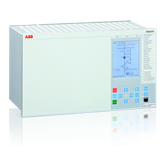
Page 62: Medium Size Graphic Hmi
Section 3 1MRK505222-UUS C Local HMI IEC07000077 V1 EN Figure 6: Medium graphic HMI, 15 controllable objects Medium size graphic HMI 3.2.1 Medium The following case sizes can be equipped with the medium size LCD: • 1/2 x 19” • 3/4 x 19”... - Page 63 Section 3 1MRK505222-UUS C Local HMI IEC07000077-CALLOUT V1 EN Figure 7: Medium size graphic HMI 1 Status indication LEDs 2 LCD 3 Indication LEDs 4 Label 5 Local/Remote LEDs 6 RJ45 port 7 Communication indication LED 8 Keypad Technical reference manual...
-
Page 64: Keypad
Section 3 1MRK505222-UUS C Local HMI Keypad The keypad is used to monitor and operate the IED. The keypad has the same look and feel in all IEDs. LCD screens and other details may differ but the way the keys function is identical. -
Page 65: Led
Section 3 1MRK505222-UUS C Local HMI Function Press to set the IED in local or remote control mode. IEC05000106 V1 EN Press to open the reset screen. IEC05000107 V1 EN Press to start the editing mode and confirm setting changes, when in editing mode. IEC05000108 V1 EN Press to navigate forward between screens and move right in editing mode. -
Page 66: Indication Leds
Section 3 1MRK505222-UUS C Local HMI LED Indication Information Flashing Terminal in test mode Red: Steady Trip command issued 3.4.3 Indication LEDs The LED indication module comprising 15 LEDs is standard in 670 series. Its main purpose is to present an immediate visual information for protection indications or alarm signals. -
Page 67: Local Hmi Related Functions
Section 3 1MRK505222-UUS C Local HMI Local HMI related functions 3.5.1 Introduction The local HMI can be adapted to the application configuration and to user preferences. • Function block LocalHMI • Function block LEDGEN • Setting parameters 3.5.2 General setting parameters Table 8: SCREEN Non group settings (basic) Name... -
Page 68: Function Block
Section 3 1MRK505222-UUS C Local HMI 3.5.3.2 Function block LocalHMI RSTLEDS HMI-ON RED-S YELLOW-S YELLOW-F RSTPULSE LEDSRST ANSI05000773-2-en.vsd ANSI05000773 V2 EN Figure 9: LocalHMI function block 3.5.3.3 Input and output signals Table 9: LocalHMI Input signals Name Type Default Description RSTLEDS BOOLEAN Input to reset the LCD-HMI LEDs... -
Page 69: Design
Section 3 1MRK505222-UUS C Local HMI Each indication LED on the local HMI can be set individually to operate in six different sequences • Two sequences operate as follow type. • Four sequences operate as latch type. • Two of the latching sequence types are intended to be used as a protection indication system, either in collecting or restarting mode, with reset functionality. - Page 70 Section 3 1MRK505222-UUS C Local HMI via the reset button and menus on the local HMI. See the operator's manual for more information. • From function input • Active indications can also be acknowledged or reset from an input, RESET, to the function.
- Page 71 Section 3 1MRK505222-UUS C Local HMI = No indication = Steady light = Flash en05000506.vsd IEC05000506 V1 EN Figure 10: Symbols used in the sequence diagrams Sequence 1 (Follow-S) This sequence follows all the time, with a steady light, the corresponding input signals. It does not react on acknowledgment or reset.
- Page 72 Section 3 1MRK505222-UUS C Local HMI Sequence 4 (LatchedAck-S-F) This sequence has the same functionality as sequence 3, but steady and flashing light have been alternated. Sequence 5 (LatchedColl-S) This sequence has a latched function and works in collecting mode. At the activation of the input signal, the indication will light up with a steady light.
- Page 73 Section 3 1MRK505222-UUS C Local HMI From disturbance length control per LED disturbance set to sequence 6 tRestart 0-100s en01000237_ansi.vsd ANSI01000237 V1 EN Figure 14: Activation of new disturbance In order not to have a lock-up of the indications in the case of a persisting signal each LED is provided with a timer, tMax, after which time the influence on the definition of a disturbance of that specific LED is inhibited.
- Page 74 Section 3 1MRK505222-UUS C Local HMI Disturbance tRestart Activating signal 1 Activating signal 2 LED 1 LED 2 Automatic reset Manual reset IEC01000239_2-en.vsd IEC01000239 V2 EN Figure 16: Operating sequence 6 (LatchedReset-S), two indications within same disturbance Figure 17 shows the timing diagram for a new indication after tRestart time has elapsed. Technical reference manual...
- Page 75 Section 3 1MRK505222-UUS C Local HMI Disturbance Disturbance tRestart tRestart Activating signal 1 Activating signal 2 LED 1 LED 2 Automatic reset Manual reset IEC01000240_2_en.vsd IEC01000240 V2 EN Figure 17: Operating sequence 6 (LatchedReset-S), two different disturbances Figure 18 shows the timing diagram when a new indication appears after the first one has reset but before tRestart has elapsed.
- Page 76 Section 3 1MRK505222-UUS C Local HMI Disturbance tRestart Activating signal 1 Activating signal 2 LED 1 LED 2 Automatic reset Manual reset IEC01000241_2_en.vsd IEC01000241 V2 EN Figure 18: Operating sequence 6 (LatchedReset-S), two indications within same disturbance but with reset of activating signal between Figure 19 shows the timing diagram for manual reset.
-
Page 77: Function Block
Section 3 1MRK505222-UUS C Local HMI Disturbance tRestart Activating signal 1 Activating signal 2 LED 1 LED 2 Automatic reset Manual reset IEC01000242_2_en.vsd IEC01000242 V2 EN Figure 19: Operating sequence 6 (LatchedReset-S), manual reset 3.5.4.3 Function block LEDGEN BLOCK NEWIND RESET LEDTEST IEC05000508_2_en.vsd... -
Page 78: Setting Parameters
Section 3 1MRK505222-UUS C Local HMI Table 12: LEDGEN Output signals Name Type Description NEWIND BOOLEAN A new signal on any of the indication inputs occurs BOOLEAN A pulse is provided when the LEDs are acknowledged 3.5.4.5 Setting parameters Table 13: LEDGEN Non group settings (basic) Name Values (Range) - Page 79 Section 3 1MRK505222-UUS C Local HMI Name Values (Range) Unit Step Default Description SeqTypeLED6 Follow-S Follow-S Sequence type for LED 6 Follow-F LatchedAck-F-S LatchedAck-S-F LatchedColl-S LatchedReset-S SeqTypeLED7 Follow-S Follow-S Sequence type for LED 7 Follow-F LatchedAck-F-S LatchedAck-S-F LatchedColl-S LatchedReset-S SeqTypeLED8 Follow-S Follow-S sequence type for LED 8...
- Page 80 Section 3 1MRK505222-UUS C Local HMI Name Values (Range) Unit Step Default Description SeqTypeLED13 Follow-S Follow-S Sequence type for LED 13 Follow-F LatchedAck-F-S LatchedAck-S-F LatchedColl-S LatchedReset-S SeqTypeLED14 Follow-S Follow-S Sequence type for LED 14 Follow-F LatchedAck-F-S LatchedAck-S-F LatchedColl-S LatchedReset-S SeqTypeLED15 Follow-S Follow-S Sequence type for LED 15...
-
Page 81: Section 4 Basic Ied Functions
Section 4 1MRK505222-UUS C Basic IED functions Section 4 Basic IED functions About this chapter This chapter presents functions that are basic to all 670 series IEDs. Typical functions in this category are time synchronization, self supervision and test mode. Authorization To safeguard the interests of our customers, both the IED and the tools that are accessing the IED are protected, by means of authorization handling. - Page 82 Section 4 1MRK505222-UUS C Basic IED functions Table 14: Pre-defined user types Access rights System Protection Design User Guest Super User SPA Guest Operator Engineer Engineer Administrator Basic setting possibilities (change setting group, control settings, limit supervision) Advanced setting possibilities (for example protection settings) Basic control possibilities (process control, no bypass)
-
Page 83: Authorization Handling In The Ied
Section 4 1MRK505222-UUS C Basic IED functions At least one user must be included in the UserAdministrator group to be able to write users, created in PCM600, to IED. 4.1.1.1 Authorization handling in the IED At delivery the default user is the SuperUser. No Log on is required to operate the IED until a user has been created with the IED User Management.. -
Page 84: Self Supervision With Internal Event List
Section 4 1MRK505222-UUS C Basic IED functions Self supervision with internal event list 4.2.1 Introduction Self supervision with internal event list function listens and reacts to internal system events, generated by the different built-in self-supervision elements. The internal events are saved in an internal event list. 4.2.2 Principle of operation The self-supervision operates continuously and includes:... - Page 85 Section 4 1MRK505222-UUS C Basic IED functions Fault Power supply fault Power supply module Watchdog I/O nodes TX overflow Fault Master resp. Supply fault ReBoot I/O INTERNAL FAIL Fault Internal Fail (CPU) I/O nodes = BIM, BOM, IOM xxxx = Inverted signal en04000520_ansi.vsd ANSI04000520 V1 EN Figure 21:...
-
Page 86: Internal Signals
Section 4 1MRK505222-UUS C Basic IED functions Some signals are available from the INTERRSIG function block. The signals from this function block are sent as events to the station level of the control system. The signals from the INTERRSIG function block can also be connected to binary outputs for signalization via output relays or they can be used as conditions for other functions if required/desired. - Page 87 Section 4 1MRK505222-UUS C Basic IED functions Table 16: Self-supervision's hardware dependent internal signals Card Name of signal Description PSM-Error Power Supply Module Error status ADOne ADOne-Error Analog In Module Error status BIM-Error Binary In Module Error status BOM-Error Binary Out Module Error status IOM-Error In/Out Module Error status MIM-Error...
-
Page 88: Run-Time Model
Section 4 1MRK505222-UUS C Basic IED functions Name of signal Reasons for activation SETCHGD This signal will generate an Internal Event to the Internal Event list if any settings are changed. SETGRPCHGD This signal will generate an Internal Event to the Internal Event list if any setting groups are changed. -
Page 89: Function Block
Section 4 1MRK505222-UUS C Basic IED functions When the signal is within measurable limits on both channels, a direct comparison of the two A/D converter channels can be performed. If the validation fails, the CPU will be informed and an alarm will be given for A/D converter failure. The ADx_Controller also supervise other parts of the A/D converter. -
Page 90: Time Synchronization
Section 4 1MRK505222-UUS C Basic IED functions Time synchronization 4.3.1 Introduction The time synchronization source selector is used to select a common source of absolute time for the IED when it is a part of a protection system. This makes it possible to compare event and disturbance data between all IEDs in a station automation system. - Page 91 Section 4 1MRK505222-UUS C Basic IED functions External Synchronization sources Time tagging and general synchronisation Protection Comm- Events and control Time- unication functions Regulator Min. pulse (Setting, SW-time technical SNTP reference manual) Connected when GPS-time is used for differential protection IRIG-B Synchronization for differential protection (ECHO-mode or GPS)
- Page 92 Section 4 1MRK505222-UUS C Basic IED functions Fast clock synchronization mode At startup and after interruptions in the GPS or IRIG B time signal, the clock deviation between the GPS time and the internal differential time system can be substantial. A new startup is also required after for example maintenance of the auxiliary voltage system.
-
Page 93: Real-Time Clock (Rtc) Operation
Section 4 1MRK505222-UUS C Basic IED functions to choose the source with the best quality, and to adjust its internal clock after this source. The maximum error of a clock can be defined as: • The maximum error of the last used synchronization message •... -
Page 94: Synchronization Alternatives
Section 4 1MRK505222-UUS C Basic IED functions Rate accuracy In the IED, the rate accuracy at cold start is 100 ppm but if the IED is synchronized for a while, the rate accuracy is approximately 1 ppm if the surrounding temperature is constant. - Page 95 Section 4 1MRK505222-UUS C Basic IED functions • Coarse message is sent every minute and comprises complete date and time, that is, year, month, day, hours, minutes, seconds and milliseconds. • Fine message is sent every second and comprises only seconds and milliseconds. The SLM module is located on the AD conversion Module (ADM).
- Page 96 Section 4 1MRK505222-UUS C Basic IED functions en05000251.vsd IEC05000251 V1 EN Figure 27: Binary minute pulses The default time-out-time for a minute pulse is two minutes, and if no valid minute pulse is received within two minutes a SYNCERR will be given. If contact bounce occurs, only the first pulse will be detected as a minute pulse.
-
Page 97: Process Bus Iec 61850-9-2Le Synchronization
Section 4 1MRK505222-UUS C Basic IED functions Synchronization via IRIG-B IRIG-B is a protocol used only for time synchronization. A clock can provide local time of the year in this format. The “B” in IRIG-B states that 100 bits per second are transmitted, and the message is sent every second. -
Page 98: Output Signals
Section 4 1MRK505222-UUS C Basic IED functions 4.3.4 Output signals Table 20: TIMEERR Output signals Name Type Description TSYNCERR BOOLEAN Time synchronization error RTCERR BOOLEAN Real time clock error 4.3.5 Setting parameters Path in the local HMI is located under Main menu/Setting/Time Path in PCM600 is located under Main menu/Settings/Time/Synchronization Table 21: TIMESYNCHGEN Non group settings (basic) - Page 99 Section 4 1MRK505222-UUS C Basic IED functions Table 22: SYNCHBIN Non group settings (basic) Name Values (Range) Unit Step Default Description ModulePosition 3 - 16 Hardware position of IO module for time synchronization BinaryInput 1 - 16 Binary input number for time synchronization BinDetection PositiveEdge PositiveEdge...
- Page 100 Section 4 1MRK505222-UUS C Basic IED functions Table 25: DSTEND Non group settings (basic) Name Values (Range) Unit Step Default Description MonthInYear January October Month in year when daylight time ends February March April June July August September October November December DayInWeek Sunday...
-
Page 101: Technical Data
Section 4 1MRK505222-UUS C Basic IED functions 4.3.6 Technical data Table 28: Time synchronization, time tagging Function Value Time tagging resolution, events and sampled measurement values 1 ms Time tagging error with synchronization once/min (minute pulse ± 1.0 ms typically synchronization), events and sampled measurement values Time tagging error with SNTP synchronization, sampled measurement ±... -
Page 102: Function Block
Section 4 1MRK505222-UUS C Basic IED functions The parameter MAXSETGR defines the maximum number of setting groups in use to switch between. ACTIVATE GROUP 6 ACTIVATE GROUP 5 ACTIVATE GROUP 4 ACTIVATE GROUP 3 ACTIVATE GROUP 2 ACTIVATE GROUP 1 +RL2 ActiveGroup IOx-Bly1... -
Page 103: Input And Output Signals
Section 4 1MRK505222-UUS C Basic IED functions SETGRPS MAXSETGR IEC05000716_2_en.vsd IEC05000716 V2 EN Figure 31: SETGRPS function block 4.4.4 Input and output signals Table 29: ActiveGroup Input signals Name Type Default Description ACTGRP1 BOOLEAN Selects setting group 1 as active ACTGRP2 BOOLEAN Selects setting group 2 as active... -
Page 104: Changelock Function Chnglck
Section 4 1MRK505222-UUS C Basic IED functions Table 32: SETGRPS Non group settings (basic) Name Values (Range) Unit Step Default Description ActiveSetGrp SettingGroup1 SettingGroup1 ActiveSettingGroup SettingGroup2 SettingGroup3 SettingGroup4 SettingGroup5 SettingGroup6 MAXSETGR 1 - 6 Max number of setting groups 1-6 ChangeLock function CHNGLCK 4.5.1 Introduction... -
Page 105: Function Block
Section 4 1MRK505222-UUS C Basic IED functions Binary input Function Activated Deactivated 4.5.3 Function block CHNGLCK LOCK IEC09000946-1-en.vsd IEC09000946 V1 EN Figure 32: CHNGLCK function block 4.5.4 Input and output signals Table 33: CHNGLCK Input signals Name Type Default Description LOCK BOOLEAN Parameter change lock... -
Page 106: Principle Of Operation
Section 4 1MRK505222-UUS C Basic IED functions restored, the IED will remain in TESTMODE with the same protection functions blocked or unblocked as before the power was removed. All testing will be done with actually set and configured values within the IED. No settings will be changed, thus mistakes are avoided. - Page 107 Section 4 1MRK505222-UUS C Basic IED functions 29-30) or an FT switch finger can supply a binary input which in turn is configured to the TESTMODE function block. Each of the functions includes the blocking from the TESTMODE function block. A typical example from the undervoltage function is shown in figure 33.
-
Page 108: Function Block
Section 4 1MRK505222-UUS C Basic IED functions 4.6.3 Function block TESTMODE INPUT ACTIVE OUTPUT SETTING NOEVENT IEC09000219-1.vsd IEC09000219 V1 EN Figure 34: TESTMODE function block 4.6.4 Input and output signals Table 35: TESTMODE Input signals Name Type Default Description INPUT BOOLEAN Sets terminal in test mode when active Table 36:... -
Page 109: Ied Identifiers
Section 4 1MRK505222-UUS C Basic IED functions IED identifiers 4.7.1 Introduction IED identifiers (TERMINALID) function allows the user to identify the individual IED in the system, not only in the substation, but in a whole region or a country. Use only characters A-Z, a-z and 0-9 in station, object and unit names. 4.7.2 Setting parameters Table 38:... -
Page 110: Setting Parameters
Section 4 1MRK505222-UUS C Basic IED functions They are very helpful in case of support process (such as repair or maintenance). 4.8.2 Setting parameters The function does not have any parameters available in the local HMI or PCM600. 4.8.3 Factory defined settings The factory defined settings are very useful for identifying a specific version and very helpful in the case of maintenance, repair, interchanging IEDs between different Substation Automation Systems and upgrading. -
Page 111: Principle Of Operation
Section 4 1MRK505222-UUS C Basic IED functions the application manual to get information about how binary inputs are brought in for one IED configuration. 4.9.2 Principle of operation The Signal matrix for binary inputs (SMBI) function , see figure 35, receives its inputs from the real (hardware) binary inputs via the Signal Matrix Tool (SMT), and makes them available to the rest of the configuration via its outputs, BI1 to BI10. -
Page 112: Signal Matrix For Binary Outputs Smbo
Section 4 1MRK505222-UUS C Basic IED functions Table 40: SMBI Output signals Name Type Description BOOLEAN Binary input 1 BOOLEAN Binary input 2 BOOLEAN Binary input 3 BOOLEAN Binary input 4 BOOLEAN Binary input 5 BOOLEAN Binary input 6 BOOLEAN Binary input 7 BOOLEAN Binary input 8... -
Page 113: Function Block
Section 4 1MRK505222-UUS C Basic IED functions 4.10.3 Function block SMBO ^BO1 ^BO2 ^BO3 ^BO4 ^BO5 ^BO6 ^BO7 ^BO8 ^BO9 BO10 ^BO10 IEC05000439-2-en.vsd IEC05000439 V2 EN Figure 36: SMBO function block 4.10.4 Input and output signals Table 41: SMBO Input signals Name Type Default... -
Page 114: Principle Of Operation
Section 4 1MRK505222-UUS C Basic IED functions 4.11.2 Principle of operation The Signal matrix for mA inputs (SMMI) function, see figure 37, receives its inputs from the real (hardware) mA inputs via the Signal Matrix Tool (SMT), and makes them available to the rest of the configuration via its analog outputs, named AI1 to AI6. -
Page 115: Signal Matrix For Analog Inputs Smai
Section 4 1MRK505222-UUS C Basic IED functions Name Type Description REAL Analog milliampere input 4 REAL Analog milliampere input 5 REAL Analog milliampere input 6 4.12 Signal matrix for analog inputs SMAI 4.12.1 Introduction Signal matrix for analog inputs function (SMAI), also known as the preprocessor function, processes the analog signals connected to it and gives information about all aspects of the analog signals connected, like the RMS value, phase angle, frequency, harmonic content, sequence components and so on. - Page 116 Section 4 1MRK505222-UUS C Basic IED functions If SMAI setting ConnectionType is Ph-Ph at least two of the inputs GRPx_A, GRPx_B and GRPx_C must be connected in order to calculate positive sequence voltage. If SMAI setting ConnectionType is Ph-N, all three inputs GRPx_A, GRPx_B and GRPx_C must be connected in order to calculate positive sequence voltage.
-
Page 117: Function Block
Section 4 1MRK505222-UUS C Basic IED functions 4.12.4 Function block SMAI1 BLOCK SPFCOUT DFTSPFC AI3P ^GRP1_A ^GRP1_B ^GRP1_C ^GRP1_N TYPE ANSI05000705-1-en.vsd ANSI05000705 V1 EN Figure 39: SMAI1 function block SMAI2 BLOCK AI3P ^GRP2_A ^GRP2_B ^GRP2_C ^GRP2_N TYPE ANSI07000130-1-en.vsd ANSI07000130 V1 EN Figure 40: SMAI2 function block 4.12.5... -
Page 118: Setting Parameters
Section 4 1MRK505222-UUS C Basic IED functions Table 45: SMAI1 Output signals Name Type Description SPFCOUT REAL Number of samples per fundamental cycle from internal DFT reference function AI3P GROUP SIGNAL Group 1 analog input 3-phase group GROUP SIGNAL Group 1 analog input 1 GROUP SIGNAL Group 1 analog input 2 GROUP SIGNAL... - Page 119 Section 4 1MRK505222-UUS C Basic IED functions Table 48: SMAI1 Non group settings (basic) Name Values (Range) Unit Step Default Description DFTRefExtOut InternalDFTRef InternalDFTRef DFT reference for external output AdDFTRefCh1 AdDFTRefCh2 AdDFTRefCh3 AdDFTRefCh4 AdDFTRefCh5 AdDFTRefCh6 AdDFTRefCh7 AdDFTRefCh8 AdDFTRefCh9 AdDFTRefCh10 AdDFTRefCh11 AdDFTRefCh12 External DFT ref DFTReference...
-
Page 120: Summation Block 3 Phase 3Phsum
Section 4 1MRK505222-UUS C Basic IED functions Table 50: SMAI2 Non group settings (basic) Name Values (Range) Unit Step Default Description DFTReference InternalDFTRef InternalDFTRef DFT reference AdDFTRefCh1 AdDFTRefCh2 AdDFTRefCh3 AdDFTRefCh4 AdDFTRefCh5 AdDFTRefCh6 AdDFTRefCh7 AdDFTRefCh8 AdDFTRefCh9 AdDFTRefCh10 AdDFTRefCh11 AdDFTRefCh12 External DFT ref ConnectionType Ph-N Ph-N... -
Page 121: Function Block
Section 4 1MRK505222-UUS C Basic IED functions 4.13.3 Function block 3PHSUM BLOCK AI3P DFTSPFC G1AI3P* G2AI3P* IEC05000441-2-en.vsd IEC05000441 V2 EN Figure 41: 3PHSUM function block 4.13.4 Input and output signals Table 52: 3PHSUM Input signals Name Type Default Description BLOCK BOOLEAN Block DFTSPFC... -
Page 122: Authority Status Athstat
Section 4 1MRK505222-UUS C Basic IED functions Table 54: 3PHSUM Non group settings (basic) Name Values (Range) Unit Step Default Description SummationType Group1+Group2 Group1+Group2 Summation type Group1-Group2 Group2-Group1 -(Group1+Group2) DFTReference InternalDFTRef InternalDFTRef DFT reference AdDFTRefCh1 External DFT ref Table 55: 3PHSUM Non group settings (advanced) Name Values (Range) -
Page 123: Function Block
Section 4 1MRK505222-UUS C Basic IED functions 4.14.3 Function block ATHSTAT USRBLKED LOGGEDON IEC06000503-2-en.vsd IEC06000503 V2 EN Figure 42: ATHSTAT function block 4.14.4 Output signals Table 56: ATHSTAT Output signals Name Type Description USRBLKED BOOLEAN At least one user is blocked by invalid password LOGGEDON BOOLEAN At least one user is logged on... -
Page 124: Function Blocks
Section 4 1MRK505222-UUS C Basic IED functions • LINKUP indicates the Ethernet link status • WARNING indicates that communication (frame rate) is higher than normal • ALARM indicates that the IED limits communication 4.15.3 Function blocks DOSFRNT LINKUP WARNING ALARM IEC09000749-1-en.vsd IEC09000749 V1 EN Figure 43:... -
Page 125: Settings
Section 4 1MRK505222-UUS C Basic IED functions Table 58: DOSOEMAB Output signals Name Type Description LINKUP BOOLEAN Ethernet link status WARNING BOOLEAN Frame rate is higher than normal state ALARM BOOLEAN Frame rate is higher than throttle state Table 59: DOSOEMCD Output signals Name Type... -
Page 127: Section 5 Differential Protection
Section 5 1MRK505222-UUS C Differential protection Section 5 Differential protection About this chapter This chapter describes the measuring principles, functions and parameters used in differential protection. Line differential protection Function description IEC 61850 IEC 60617 ANSI/IEEE C37.2 identification identification device number Line differential protection, 3 CT sets, 3Id/I>... -
Page 128: Introduction
Section 5 1MRK505222-UUS C Differential protection 5.1.1 Introduction 5.1.1.1 Line differential protection, 3 or 6 CT sets L3CPDIF, L6CPDIF Line differential protection applies the Kirchhoff's law and compares the currents entering and leaving the protected multi-terminal circuit, consisting of overhead power lines, power transformers and cables. - Page 129 Section 5 1MRK505222-UUS C Differential protection Protected zone Communication Channel Communication Channel Communication Channel ANSI05000040_2_en.vsd ANSI05000040 V2 EN Figure 47: Example of application on a three-terminal line with breaker-and-a-half breaker arrangements The current differential algorithm provides high sensitivity for internal faults, at the same time as it has excellent stability for external faults.
-
Page 130: Line Differential Protection 3 Or 6 Ct Sets, With In-Zone Transformers Lt3Cpdif, Lt6Cpdif
Section 5 1MRK505222-UUS C Differential protection A line charging current compensation provides increased sensitivity of Line differential protection. 5.1.1.2 Line differential protection 3 or 6 CT sets, with in-zone transformers LT3CPDIF, LT6CPDIF Two two-winding power transformers, or one three-winding power transformer, can be included in the line differential protection zone. - Page 131 Section 5 1MRK505222-UUS C Differential protection communication channel is needed between every IED included in the same line differential protection zone. In the latter, current samples are sent from all slave IEDs to one master IED where the evaluation is made, and trip signals are sent to the remote ends when needed.
-
Page 132: Principle Of Operation
Section 5 1MRK505222-UUS C Differential protection Protected zone Communication Channels en05000044_ansi.vsd ANSI05000044 V1 EN Figure 50: Five terminal line with master-slave system Current samples from IEDs located geographically apart from each other, must be time coordinated so that the current differential algorithm can be executed correctly. In IED, it is possible to make this coordination in two different ways. - Page 133 Section 5 1MRK505222-UUS C Differential protection Remote end Local end Remote end RED670 LDCM Local end RED670 Current samples from local end Analog Input Module Converter Current Pre-processing samples from Block remote end LDCM Line Diffferential Function [magnitude] Trip by unrestrained differential protection CH1IL1RE CH1IL1IM Calculation of...
- Page 134 Section 5 1MRK505222-UUS C Differential protection Module (LDCM) where they are time coordinated with the local current samples, and interpolated in order to be comparable with the local samples. In the Pre-Processing Block, the real and imaginary parts of the fundamental frequency phase currents and negative sequence currents are derived.
- Page 135 Section 5 1MRK505222-UUS C Differential protection Operate current [ in pu of IBase] Operate unconditionally UnrestrainedLimit Operate IdMinHigh conditionally Section 1 Section 2 Section 3 SlopeSection3 IdMin SlopeSection2 Restrain EndSection1 Restrain current [ in pu of IBase] EndSection2 en05000300.vsd IEC05000300 V1 EN Figure 52: Description of the restrained-, and the unrestrained operate characteristics...
- Page 136 Section 5 1MRK505222-UUS C Differential protection The second analysis is the 2 and 5 harmonic analysis on the differential current. Occurrence of these harmonics over a level that is set separately for each one will block tripping action from the biased slope evaluation. The third analysis is the negative sequence current analysis.
- Page 137 Section 5 1MRK505222-UUS C Differential protection When a fault is classified as internal by the negative sequence fault discriminator, a trip is issued under the condition that the dual slope restrained function has been picked up , while a classification as external fault results in an increase of the restrained characteristic trip values IdMinHigh.
- Page 138 Section 5 1MRK505222-UUS C Differential protection Trip unrestrained A TRIP Trip unrestrained B Trip unrestrained C TR_A Pickup A Pickup B Pickup C TR_B TR_C PU_A IdMinHigh PU_B IdMinHigh PU_C IdMinHigh Internal fault NegSeqDiffEn tIdMinHigh External fault Line energizing Diff curr A 2 harm Diff curr A 5 harm...
- Page 139 Section 5 1MRK505222-UUS C Differential protection • A pickup in one phase, gives a trip under the condition that the content of 2 harmonic is below the set level for these harmonics. Otherwise it is blocked as long as the harmonic is above the set level. However, when a line is energized the current setting value IdMinHigh is used.
-
Page 140: Time Synchronization
Section 5 1MRK505222-UUS C Differential protection 5.1.2.2 Time synchronization In a numerical line differential protection, current samples from protections located geographically apart from each other, must be time coordinated so that the currents from the different line ends can be compared without introducing irrelevant errors. Accuracy requirements on this time coordination are extremely high. -
Page 141: Analog Signal Communication For Line Differential Protection
Section 5 1MRK505222-UUS C Differential protection (Equation 3) EQUATION1359 V1 EN Δt is calculated every time a telegram is received, and the time difference is then used to adjust and interpolate the current measurements from the remote end before the current differential algorithm is executed. - Page 142 Section 5 1MRK505222-UUS C Differential protection In breaker-and-a-half arrangements, there are two local currents meaning two 64 kbit/s channels to each remote substation. Alternatively, it is possible to add together the two local currents before sending them and in that way reduce the number of communication channels needed.
- Page 143 Section 5 1MRK505222-UUS C Differential protection The master-slave configuration is achieved by setting parameter Operation in the slaves to Disabled for Line differential protection function, and setting parameter ChannelMode to Enabled for the LDCMs in the slaves. Test mode Line differential protection function in one IED can be set in test mode. This can block the trip outputs on that IED, and set the remote IEDs in a remote test mode, so that injected currents can be echoed back phase shifted and with a settable magnitude.
-
Page 144: Open Ct Detection Feature
Section 5 1MRK505222-UUS C Differential protection Telecom. Network Telecom. Network Primary Channel Hot Standby Channel en05000289_ansi.vsd ANSI05000289 V1 EN Figure 59: Direct fiber optical connection between two IEDs with LDOM over longer distances. If communication is lost on the primary channel, switchover to the secondary channel is made after a settable time delay RedChSwTime. - Page 145 Section 5 1MRK505222-UUS C Differential protection mistake open circuited on the secondary side. Note that this feature can only detect interruption of one CT phase current at the time. If two or even all three-phase currents of one set of CT are accidentally interrupted at the same time this feature cannot operate and Line differential protection generates trip signal, if the false differential current is sufficiently high.
-
Page 146: Binary Signal Transfer
Section 5 1MRK505222-UUS C Differential protection Output OPENCT provides instant information to indicate that open CT circuit has been detected Output OPENCTAL provides time delayed alarm that the open CT circuit has been detected. Time delay is defined by setting parameter tOCTAlarmDelay. Integer output OPENCTIN provides information on the local HMI regarding which open CT circuit has been detected (1=CT input No 1;... -
Page 147: Function Block
Section 5 1MRK505222-UUS C Differential protection 5.1.3 Function block L3CPDIF (87L) I3P1* TRIP I3P2* TR_A I3P3* TR_B TR_C TRIPRES TRIPUNRE TRIPENHA PICKUP PU_A PU_B PU_C BLK2H BLK2H_A BLK2H_B BLK2H_C BLK5H BLK5H_A BLK5H_B BLK5H_C ALARM OPENCT OPENCTAL ID_A ID_B ID_C IDMAG_A IDMAG_B IDMAG_C IBIAS... - Page 148 Section 5 1MRK505222-UUS C Differential protection L6CPDIF (87L) I3P1* TRIP I3P2* TR_A I3P3* TR_B I3P4* TR_C I3P5* TRIPRES I3P6* TRIPUNRE TRIPENHA PICKUP PU_A PU_B PU_C BLK2H BLK2H_A BLK2H_B BLK2H_C BLK5H BLK5H_A BLK5H_B BLK5H_C ALARM OPENCT OPENCTAL ID_A ID_B ID_C IDMAG_A IDMAG_B IDMAG_C IBIAS...
- Page 149 Section 5 1MRK505222-UUS C Differential protection LT3CPDIF (87LT) I3P1* TRIP I3P2* TR_A I3P3* TR_B TR_C TRIPRES TRIPUNRE TRIPENHA PICKUP PU_A PU_B PU_C BLK2H BLK2H_A BLK2H_B BLK2H_C BLK5H BLK5H_A BLK5H_B BLK5H_C ALARM OPENCT OPENCTAL ID_A ID_B ID_C IDMAG_A IDMAG_B IDMAG_C IBIAS IDMAG_NS ANSI06000254-2-en.vsd ANSI06000254 V2 EN...
- Page 150 Section 5 1MRK505222-UUS C Differential protection LT6CPDIF (87LT) I3P1* TRIP I3P2* TR_A I3P3* TR_B I3P4* TR_C I3P5* TRIPRES I3P6* TRIPUNRE TRIPENHA PICKUP PU_A PU_B PU_C BLK2H BLK2H_A BLK2H_B BLK2H_C BLK5H BLK5H_A BLK5H_B BLK5H_C ALARM OPENCT OPENCTAL ID_A ID_B ID_C IDMAG_A IDMAG_B IDMAG_C IBIAS...
-
Page 151: Input And Output Signals
Section 5 1MRK505222-UUS C Differential protection 5.1.4 Input and output signals Table 60: L3CPDIF (87L) Input signals Name Type Default Description I3P1 GROUP Three phase current grp1 samples and DFT values SIGNAL I3P2 GROUP Three phase current grp1 samples and DFT values SIGNAL I3P3 GROUP... - Page 152 Section 5 1MRK505222-UUS C Differential protection Name Type Description IDMAG_A REAL Magnitude of fund. freq. differential current, phase A IDMAG_B REAL Magnitude of fund. freq. differential current, phase B IDMAG_C REAL Magnitude of fund. freq. differential current, phase C IBIAS REAL Magnitude of the bias current, common for phase A,B.C IDMAG_NS...
- Page 153 Section 5 1MRK505222-UUS C Differential protection Name Type Description BLK2H_C BOOLEAN Block signal due to second harmonic Phase C BLK5H BOOLEAN Block signal due to fifth harmonic BLK5H_A BOOLEAN Block signal due to fifth harmonic phase A BLK5H_B BOOLEAN Block signal due to fifth harmonic phase B BLK5H_C BOOLEAN Block signal due to fifth harmonic phase C...
- Page 154 Section 5 1MRK505222-UUS C Differential protection Name Type Description PU_A BOOLEAN Pickup signal from phase A PU_B BOOLEAN Pickup signal from phase B PU_C BOOLEAN Pickup signal from phase C BLK2H BOOLEAN Block signal due to second harmonic BLK2H_A BOOLEAN Block signal due to second harmonic phase A BLK2H_B BOOLEAN...
- Page 155 Section 5 1MRK505222-UUS C Differential protection Table 67: LT6CPDIF (87LT) Output signals Name Type Description TRIP BOOLEAN Main Trip Signal TR_A BOOLEAN Trip signal from phase A TR_B BOOLEAN Trip signal from phase B TR_C BOOLEAN Trip signal from phase C TRIPRES BOOLEAN Trip by restrained differential 87L...
-
Page 156: Setting Parameters
Section 5 1MRK505222-UUS C Differential protection Table 69: LDLPDIF (87L) Output signals Name Type Description TRIP BOOLEAN General trip from differential protection system TR_A BOOLEAN Trip signal from phase A TR_B BOOLEAN Trip signal from phase B TR_C BOOLEAN Trip signal from phase C TRLOCAL BOOLEAN Trip from local differential function... - Page 157 Section 5 1MRK505222-UUS C Differential protection Name Values (Range) Unit Step Default Description CurveType ANSI Ext. inv. IEC Def. Time 19 curve types. Example: 15 for definite time ANSI Very inv. delay. ANSI Norm. inv. ANSI Mod. inv. ANSI Def. Time L.T.E.
- Page 158 Section 5 1MRK505222-UUS C Differential protection Name Values (Range) Unit Step Default Description OpenCTEnable Disabled Enabled Open CTEnable Off/On Enabled tOCTAlarmDelay 0.100 - 10.000 0.001 1.000 Open CT: time in s to alarm after an open CT is detected tOCTResetDelay 0.100 - 10.000 0.001 0.250...
- Page 159 Section 5 1MRK505222-UUS C Differential protection Name Values (Range) Unit Step Default Description IMaxAddDelay 0.20 - 5.00 0.01 1.00 Below limit, extra delay can be applied, multiple of IBase tDefTime 0.000 - 6.000 0.001 0.000 Definite time additional delay in seconds tMinInv 0.001 - 6.000 0.001...
- Page 160 Section 5 1MRK505222-UUS C Differential protection Name Values (Range) Unit Step Default Description OpenCTEnable Disabled Enabled Open CT detection feature. Open CTEnable Enabled Off/On tOCTAlarmDelay 0.100 - 10.000 0.001 1.000 Open CT: time in s to alarm after an open CT is detected tOCTResetDelay 0.100 - 10.000...
- Page 161 Section 5 1MRK505222-UUS C Differential protection Name Values (Range) Unit Step Default Description IMaxAddDelay 0.20 - 5.00 0.01 1.00 Below limit, extra delay can be applied, multiple of IBase tDefTime 0.000 - 6.000 0.001 0.000 Definite time additional delay in seconds tMinInv 0.001 - 6.000 0.001...
- Page 162 Section 5 1MRK505222-UUS C Differential protection Name Values (Range) Unit Step Default Description 0.01 - 1000.00 0.01 1.00 Settable curve parameter, user- programmable curve type. 0.01 - 1000.00 0.01 1.00 Settable curve parameter, user- programmable curve type. OpenCTEnable Disabled Enabled Open CT detection feature.
- Page 163 Section 5 1MRK505222-UUS C Differential protection Name Values (Range) Unit Step Default Description RatVoltW1TraB 1.0 - 9999.9 130.0 Transformer B rated voltage (kV) on winding 1 (HV winding) RatVoltW2TraB 1.0 - 9999.9 130.0 Transformer B rated voltage (kV) on winding 2 (LV winding) ClockNumTransB 0 [0 deg]...
- Page 164 Section 5 1MRK505222-UUS C Differential protection Name Values (Range) Unit Step Default Description IMaxAddDelay 0.20 - 5.00 0.01 1.00 Below limit, extra delay can be applied, multiple of IBase tDefTime 0.000 - 6.000 0.001 0.000 Definite time additional delay in seconds tMinInv 0.001 - 6.000 0.001...
- Page 165 Section 5 1MRK505222-UUS C Differential protection Name Values (Range) Unit Step Default Description OpenCTEnable Disabled Enabled Open CTEnable Off/On Enabled tOCTAlarmDelay 0.100 - 10.000 0.001 1.000 Open CT: time in s to alarm after an open CT is detected tOCTResetDelay 0.100 - 10.000 0.001 0.250...
-
Page 166: Technical Data
Section 5 1MRK505222-UUS C Differential protection Name Values (Range) Unit Step Default Description TraBOnInpCh No Transf B No Transf B Power transformer B applied on input channel RatVoltW1TraB 1.0 - 9999.9 130.0 Transformer B rated voltage (kV) on winding 1 (HV winding) RatVoltW2TraB 1.0 - 9999.9 130.0... -
Page 167: 1Ph High Impedance Differential Protection Hzpdif (87)
Section 5 1MRK505222-UUS C Differential protection Function Range or value Accuracy IBase EndSection 2 (100–1000)% of IBase Unrestrained limit function (100–5000)% of ± 1.0% of I at I ≤ I ± 1.0% of I at I > I Second harmonic blocking (5.0–100.0)% of fundamental ±... -
Page 168: Principle Of Operation
Section 5 1MRK505222-UUS C Differential protection 5.2.3 Principle of operation The 1Ph High impedance differential protection (HZPDIF, 87) function is based on one current input with external stabilizing resistor and voltage dependent resistor. Three functions can be used to provide a three phase differential protection function. The stabilizing resistor value is calculated from the IED function operating value V TripPickup calculated to achieve through fault stability. -
Page 169: Function Block
Section 5 1MRK505222-UUS C Differential protection 5.2.4 Function block HZPDIF (87) ISI* TRIP BLOCK ALARM BLKTR MEASVOLT ANSI05000363-2-en.vsd ANSI05000363 V2 EN Figure 66: HZPDIF (87) function block 5.2.5 Input and output signals Table 84: HZPDIF (87) Input signals Name Type Default Description GROUP... -
Page 170: Technical Data
Section 5 1MRK505222-UUS C Differential protection 5.2.7 Technical data Table 87: HZPDIF (87)technical data Function Range or value Accuracy Operate voltage (20-400) V ± 1.0% of I I=V/R Reset ratio >95% Maximum continuous V>Pickup /SeriesResistor ≤200 W power Operate time 10 ms typically at 0 to 10 x V Reset time 105 ms typically at 10 to 0 x V... -
Page 171: Principle Of Operation
Section 5 1MRK505222-UUS C Differential protection Zero sequence criterions takes the zero sequence current as input. It increases the security of protection during the high impedance fault conditions. Low voltage criterion takes the phase voltages and phase-to-phase voltages as inputs. It increases the security of protection when the three-phase fault occurred on the weak end side. - Page 172 Section 5 1MRK505222-UUS C Differential protection Phase-to-phase current variation Phase-to-phase current variation one is main startup element. It covers most of the abnormal status of the system. The phase-to-phase current variation fails in high impedance faults, three-phase fault on weak side and switch onto fault on unloaded line because of low sensitivity in these cases.
- Page 173 Section 5 1MRK505222-UUS C Differential protection Time Delay CV Pick Up VAB cont Time Delay CV Current variation Pick Up VBC subfunction Time Delay CV Pick Up VCA STCV cont ANSI10000295-1-en.vsd ANSI10000295 V1 EN Figure 67: Current variation logic diagram Time Delay CV is the time setting for the change of current criterion.
- Page 174 Section 5 1MRK505222-UUS C Differential protection The zero sequence current criterion can be blocked by activating the BLK3I0 input signal. Low voltage criterion Low voltage criterion is mainly for detection of the three phase faults occurring on weak side with pre fault no load condition. The low voltage criterion takes the voltage phase values, voltage phase-to-phase values and remote startup signals as inputs.
- Page 175 Section 5 1MRK505222-UUS C Differential protection a<b PU_UC PU_37 BLUC BLOCK ANSI09000780-1-en.vsd ANSI09000780 V1 EN Figure 70: Low current criterion logic diagram Security logic for differential protection The configuration for the additional security logic for differential protection is shown in fig 71. The function will release tripping of the line differential protection up to the end of timer tStUpReset.
-
Page 176: Function Block
Section 5 1MRK505222-UUS C Differential protection 5.3.3 Function block STSGGIO (11REL) I3P* BFI_3P V3P* Pick Up VAB BLOCK Pick Up VBC BLKCV Pick Up VCA BLUC PU_UC BLK3I0 Pick Up 3I0 BLKUV 27 PU REMSTEP ANSI09000781-1-en.vsd ANSI09000781 V1 EN Figure 72: STSGGIO (11) function block 5.3.4 Input and output signals... -
Page 177: Setting Parameters
Section 5 1MRK505222-UUS C Differential protection 5.3.5 Setting parameters Table 90: STSGGIO (11REL) Group settings (basic) Name Values (Range) Unit Step Default Description Operation Disabled Disabled Operation Off/On Enabled IBase 1 - 99999 3000 Base setting for current in A VBase 0.05 - 2000.00 0.05... -
Page 178: Technical Data
Section 5 1MRK505222-UUS C Differential protection 5.3.6 Technical data Table 92: STSGGIO (11) technical data Function Range or value Accuracy Operate current, zero sequence (1-100)% of lBase ±1,0% of I Operate current, low operation (1-100)% of lBase ±1,0% of I Operate voltage, phase to neutral (1-100)% of VBase ±... -
Page 179: Section 6 Impedance Protection
Section 6 1MRK505222-UUS C Impedance protection Section 6 Impedance protection About this chapter This chapter describes distance protection and associated functions. It includes function blocks, logic diagrams and data tables with information about distance protection, automatic switch onto fault, weak end in-feed and other associated functions. -
Page 180: Principle Of Operation
Section 6 1MRK505222-UUS C Impedance protection ZMQPDIS (21) together with Phase selection with load encroachment FDPSPDIS (21) has functionality for load encroachment, which increases the possibility to detect high resistive faults on heavily loaded lines, as shown in figure73. Forward operation Reverse operation... -
Page 181: Impedance Characteristic
Section 6 1MRK505222-UUS C Impedance protection Figure presents an outline of the different measuring loops for up to five, impedance- measuring zones. There are 3 to 5 zones depending on product type and variant. Zone 1 A- B B - C Zone 2 B -C C- A... - Page 182 Section 6 1MRK505222-UUS C Impedance protection (Ohm/loop) RFPG R1+Rn RFPG X0-X1 X1+Xn R0-R1 (Ohm/loop) RFPG RFPG X1+Xn RFPG R1+Rn RFPG ANSI05000661-3-en.vsd ANSI05000661 V3 EN Figure 75: Characteristic for phase-to-ground measuring, ohm/loop domain Technical reference manual...
- Page 183 Section 6 1MRK505222-UUS C Impedance protection (Ohm/phase) RFPP RFPP X PE X RVPE XNRV X PG X RVPG X PE X RVPE XNRV XNRV X PE X FWPE X PE X FWPE X PG X FWPG XNFW XNFW XNFW (Ohm/phase) RFPP RFPP RFPP...
- Page 184 Section 6 1MRK505222-UUS C Impedance protection R1 + j X1 Phase-to-ground element Phase-to-ground RFPG fault in phase A (Arc + tower resistance) (R0-R1)/3 + j (X0-X1)/3 ) Phase-to-phase R1 + j X1 element A-B Phase-to-phase RFPP fault in phase A-B (Arc resistance) R1 + j X1 R1 + j X1...
-
Page 185: Minimum Operating Current
Section 6 1MRK505222-UUS C Impedance protection and reverse direction (there are different forward and reverse settings - Zx and ZxRev respectively, where x = 1 - 5). Therefore, all reach settings apply to both directions. Non-directional Forward Reverse en05000182.vsd IEC05000182 V1 EN Figure 78: Directional operating modes of the distance measuring zones 6.1.3.3... -
Page 186: Measuring Principles
Section 6 1MRK505222-UUS C Impedance protection 6.1.3.4 Measuring principles Fault loop equations use the complex values of voltage, current, and changes in the current. Apparent impedances are calculated and compared with the set limits. The apparent impedances at phase-to-phase faults follow equation (example for a phase A to phase B fault). - Page 187 Section 6 1MRK505222-UUS C Impedance protection Here IN is a phasor of the residual current in IED point. This results in the same reach along the line for all types of faults. The apparent impedance is considered as an impedance loop with resistance R and reactance X.
-
Page 188: Directional Impedance Element For Quadrilateral Characteristics
Section 6 1MRK505222-UUS C Impedance protection 2 p f × × (Equation 9) EQUATION356 V1 EN where: designates the real component of current and voltage, designates the imaginary component of current and voltage and designates the rated system frequency The algorithm calculates R measured resistance from the equation for the real value of the voltage and substitutes it in the equation for the imaginary part. - Page 189 Section 6 1MRK505222-UUS C Impedance protection For the AB element, the equation in forward direction is according to. × × < < ArgDir L L M ArgNeg (Equation 13) EQUATION1553 V2 EN where: AngDir is the setting for the lower boundary of the forward directional characteristic, by default set to 15 (= -15 degrees) and AngNegRes is the setting for the upper boundary of the forward directional characteristic, by default set to 115 degrees, see figure 79.
- Page 190 Section 6 1MRK505222-UUS C Impedance protection AngNegRes AngDir en05000722_ansi.vsd ANSI05000722 V1 EN Figure 79: Setting angles for discrimination of forward and reverse fault in Directional impedance quadrilateral function ZDRDIR (21D) The reverse directional characteristic is equal to the forward characteristic rotated by 180 degrees.
-
Page 191: Simplified Logic Diagrams
Section 6 1MRK505222-UUS C Impedance protection 6.1.3.6 Simplified logic diagrams Distance protection zones The design of the distance protection zones are presented for all measuring loops: phase- to-ground as well as phase-to-phase. Phase-to-ground related signals are designated by AG, BG and CG. The phase-to- phase signals are designated by AB, BC and CA. - Page 192 Section 6 1MRK505222-UUS C Impedance protection PUZMPP PHSEL NDIR_AB NDIR_BC NDIR_CA NDIR_A NDIR_B NDIR_C STNDPE LOVBZ PHPUND BLOCK BLOCFUNC ANSI99000557-1-en.vsd ANSI99000557 V2 EN Figure 80: Conditioning by a group functional input signal PHSEL, external start condition Composition of the phase pickup signals for a case, when the zone operates in a non- directional mode, is presented in figure 81.
- Page 193 Section 6 1MRK505222-UUS C Impedance protection NDIR_A NDIR_B PU_A NIDR_C 15ms NDIR_AB PU_B 15ms NDIR_BC PU_C NDIR_CA 15ms PICKUP 15ms ANSI09000889-1-en.vsd ANSI09000889 V1 EN Figure 81: Composition of pickup signals in non-directional operating mode Results of the directional measurement enter the logic circuits, when the zone operates in directional (forward or reverse) mode, as shown in figure 82.
- Page 194 Section 6 1MRK505222-UUS C Impedance protection NDIR_A DIR_A PU_ZMPG NDIR_B DIR_B NDIR_C PU_A DIR_C 15 ms NDIR_AB DIR_AB PU_B 15 ms NDIR_BC DIR_BC PU_C NDIR_CA 15 ms DIR_CA PU_ZMPP PICKUP 15 ms ANSI09000888-2-en.vsd ANSI09000888 V2 EN Figure 82: Composition of pickup signals in directional operating mode Tripping conditions for the distance protection zone one are symbolically presented in figure 83.
-
Page 195: Function Block
Section 6 1MRK505222-UUS C Impedance protection Timer tPP=enable PUZMPP 0-tPP BLKFUNC 0-tPG Timer tPG=enable PUZMPG TRIP BLKTR 15 ms TR_A PU_A TR_B PU_B TR_C PU_C ANSI09000887-2-en.vsd ANSI09000887 V2 EN Figure 83: Tripping logic for the distance protection zone 6.1.4 Function block ZMQPDIS (21) I3P* TRIP... -
Page 196: Input And Output Signals
Section 6 1MRK505222-UUS C Impedance protection ZMQAPDIS (21) I3P* TRIP V3P* TR_A BLOCK TR_B LOVBZ TR_C BLKTR PICKUP PHSEL PU_A DIRCND PU_B PU_C PHPUND ANSI09000884-1-en.vsd ANSI09000884 V1 EN Figure 85: ZMQAPDIS (21) function block (zone 2 - 5) ZDRDIR I3P* STDIRCND U3P* IEC10000007-1-en.vsd... - Page 197 Section 6 1MRK505222-UUS C Impedance protection Name Type Description PU_A BOOLEAN Pickup signal from phase A PU_B BOOLEAN Pickup signal from phase B PU_C BOOLEAN Pickup signal from phase C PHPUND BOOLEAN Non-directional pickup, issued from any selected phase or loop Table 95: ZMQAPDIS (21) Input signals Name...
-
Page 198: Setting Parameters
Section 6 1MRK505222-UUS C Impedance protection Table 98: ZDRDIR (21D) Output signals Name Type Description STDIRCND INTEGER Binary coded directional information per measuring loop 6.1.6 Setting parameters Signals and settings for ZMQPDIS are valid for zone 1 while signals and settings for ZMQAPDIS are valid for zone 2 - 5 Table 99: ZMQPDIS (21) Group settings (basic) Name... - Page 199 Section 6 1MRK505222-UUS C Impedance protection Name Values (Range) Unit Step Default Description IMinPUPP 10 - 1000 Minimum pickup delta current (2 x current of lagging phase) for Phase-to-phase loops IMinPUPG 10 - 1000 Minimum pickup phase current for Phase-to- ground loops IMinOpIR 5 - 1000...
-
Page 200: Technical Data
Section 6 1MRK505222-UUS C Impedance protection Table 101: ZDRDIR (21D) Group settings (basic) Name Values (Range) Unit Step Default Description IBase 1 - 99999 3000 Base setting for current level VBase 0.05 - 2000.00 0.05 400.00 Base setting for voltage level IMinPUPP 5 - 30 Minimum pickup delta current (2 x current of... -
Page 201: Distance Measuring Zone, Quadrilateral Characteristic For Series Compensated Lines Zmcpdis (21), Zmcapdis (21), Zdsrdir (21D)
Section 6 1MRK505222-UUS C Impedance protection Distance measuring zone, quadrilateral characteristic for series compensated lines ZMCPDIS (21), ZMCAPDIS (21), ZDSRDIR (21D) Function description IEC 61850 IEC 60617 ANSI/IEEE C37.2 identification identification device number Distance measuring zone, quadrilateral ZMCPDIS characteristic for series compensated lines (zone 1) S00346 V1 EN Distance measuring zone, quadrilateral... -
Page 202: Principle Of Operation
Section 6 1MRK505222-UUS C Impedance protection Forward operation Reverse operation en05000034.vsd IEC05000034 V1 EN Figure 87: Typical quadrilateral distance protection zone with load encroachment function activated The independent measurement of impedance for each fault loop together with a sensitive and reliable built in phase selection makes the function suitable in applications with single phase auto-reclosing. -
Page 203: Impedance Characteristic
Section 6 1MRK505222-UUS C Impedance protection Zone 1 A- B B - C Zone 2 B -C C- A A- B Zone 3 A- B Zone 4 A- B C -A Zone 5 A- B B -C C -A Zone 6 A- B B - C ANSI05000458-2-en.vsd... - Page 204 Section 6 1MRK505222-UUS C Impedance protection (Ohm/loop) R1PG+RNFw X PG X FwPG XNFw RFRvPG RFFwPG X RvPG X PG X RVPG X PE X RVPE XNRV × XNRv XNFw XNRV X FwPG X PE X FWPE X PG X FWPG XNFW XNFW R PG...
- Page 205 Section 6 1MRK505222-UUS C Impedance protection (Ohm/phase) RFRvPP R1PP RFFwPP X PE X RVPE XNRV X PG X RVPG X PE X RVPE XNRV XNRV X PE X FWPE X PE X FWPE X PG X FWPG XNFW XNFW XNFW X1FwPP (Ohm/phase) RFRvPP...
- Page 206 Section 6 1MRK505222-UUS C Impedance protection R1 + j X1 Phase-to-ground element Phase-to-ground RFPG fault in phase A (Arc + tower resistance) (R0-R1)/3 + j (X0-X1)/3 ) Phase-to-phase R1 + j X1 element A-B Phase-to-phase RFPP fault in phase A-B (Arc resistance) R1 + j X1 R1 + j X1...
-
Page 207: Minimum Operating Current
Section 6 1MRK505222-UUS C Impedance protection Non-directional Forward Reverse en05000182.vsd IEC05000182 V1 EN Figure 92: Directional operating modes of the distance measuring zone 6.2.2.3 Minimum operating current The operation of Distance measuring zone, quadrilateral characteristic for series compensated lines (ZMCPDIS,ZMCAPDIS, 21) is blocked if the magnitude of input currents fall below certain threshold values. -
Page 208: Measuring Principles
Section 6 1MRK505222-UUS C Impedance protection 6.2.2.4 Measuring principles Fault loop equations use the complex values of voltage, current, and changes in the current. Apparent impedances are calculated and compared with the set limits. The calculation of the apparent impedances at ph-ph faults follows equation (example for a phase A to phase B fault). - Page 209 Section 6 1MRK505222-UUS C Impedance protection Here IN is a phasor of the residual current at the IED point. This results in the same reach along the line for all types of faults. The apparent impedance is considered as an impedance loop with resistance R and reactance X.
-
Page 210: Directionality For Series Compensation
Section 6 1MRK505222-UUS C Impedance protection 2 p f × × (Equation 19) EQUATION356 V1 EN where: designates the real component of current and voltage, designates the imaginary component of current and voltage and designates the rated system frequency The algorithm calculates Rm measured resistance from the equation for the real value of the voltage and substitute it in the equation for the imaginary part. - Page 211 Section 6 1MRK505222-UUS C Impedance protection The polarizing voltage is a memorized positive sequence voltage. The memory is continuously synchronized via a positive sequence filter. The memory is starting to run freely instantaneously when a voltage change is detected in any phase. A non- directional impedance measurement is used to detect a fault and identify the faulty phase or phases.
- Page 212 Section 6 1MRK505222-UUS C Impedance protection < < AngDir AngNeg (Equation 23) EQUATION2007 V2 EN where: AngDir is the setting for the lower boundary of the forward directional characteristic, by default set to 15 (= -15 degrees) and AngNegRes is the setting for the upper boundary of the forward directional characteristic, by default set to 115 degrees, see figure 93.
-
Page 213: Simplified Logic Diagrams
Section 6 1MRK505222-UUS C Impedance protection The reverse directional characteristic is equal to the forward characteristic rotated by 180 degrees. 6.2.2.6 Simplified logic diagrams Distance protection zones The design of distance protection zones are presented for all measuring loops: phase-to- ground as well as phase-to-phase. - Page 214 Section 6 1MRK505222-UUS C Impedance protection PUZMPP PHSEL NDIR_AB NDIR_BC NDIR_CA NDIR_A NDIR_B NDIR_C STNDPE LOVBZ PHPUND BLOCK BLOCFUNC ANSI99000557-1-en.vsd ANSI99000557 V2 EN Figure 94: Conditioning by a group functional input signal PHSEL Composition of the phase pickup signals for a case, when the zone operates in a non- directional mode, is presented in figure 95.
- Page 215 Section 6 1MRK505222-UUS C Impedance protection NDIR_A NDIR_B PU_A NIDR_C NDIR_AB PU_B NDIR_BC PU_C NDIR_CA PICKUP en00000488-1_ansi.vsd ANSI00000488 V2 EN Figure 95: Composition of pickup signals in non-directional operating mode Results of the directional measurement enter the logic circuits, when the zone operates in directional (forward or reverse) mode, as shown in figure 96.
- Page 216 Section 6 1MRK505222-UUS C Impedance protection NDIR_A DIR_A PU_ZMPG NDIR_B DIR_B NDIR_C PU_A DIR_C 15 ms NDIR_AB DIR_AB PU_B 15 ms NDIR_BC DIR_BC PU_C NDIR_CA 15 ms DIR_CA PU_ZMPP PICKUP 15 ms ANSI09000888-2-en.vsd ANSI09000888 V2 EN Figure 96: Composition of pickup signals in directional operating mode Tripping conditions for the distance protection zone one are symbolically presented in figure 97.
-
Page 217: Function Block
Section 6 1MRK505222-UUS C Impedance protection Timer tPP=enable PUZMPP 0-tPP BLKFUNC 0-tPG Timer tPG=enable PUZMPG TRIP BLKTR 15 ms TR_A PU_A TR_B PU_B TR_C PU_C ANSI09000887-2-en.vsd ANSI09000887 V2 EN Figure 97: Tripping logic for the distance protection zone one 6.2.3 Function block ZMCPDIS (21) I3P*... -
Page 218: Input And Output Signals
Section 6 1MRK505222-UUS C Impedance protection ZMCAPDIS (21) I3P* TRIP V3P* TR_A BLOCK TR_B LOVBZ TR_C BLKTR PICKUP PHSEL PU_A DIRCND PU_B PU_C PHPUND ANSI09000890-1-en.vsd ANSI09000890 V1 EN Figure 99: ZMCAPDIS (21) function block ZDSRDIR (21D) I3P* PUFW V3P* PUREV STDIRCND ANSI07000035-2-en.vsd ANSI07000035 V2 EN... - Page 219 Section 6 1MRK505222-UUS C Impedance protection Table 104: ZMCPDIS (21) Output signals Name Type Description TRIP BOOLEAN General Trip, issued from any phase or loop TR_A BOOLEAN Trip signal from phase A TR_B BOOLEAN Trip signal from phase B TR_C BOOLEAN Trip signal from phase C PICKUP...
-
Page 220: Setting Parameters
Section 6 1MRK505222-UUS C Impedance protection Table 107: ZDSRDIR (21D) Input signals Name Type Default Description GROUP Group connection for current SIGNAL GROUP Group connection for voltage SIGNAL Table 108: ZDSRDIR (21D) Output signals Name Type Description PUFW BOOLEAN Pickup in forward direction PUREV BOOLEAN Pickup in reverse direction... - Page 221 Section 6 1MRK505222-UUS C Impedance protection Name Values (Range) Unit Step Default Description 0.000 - 60.000 0.001 0.000 Time delay of trip, Ph-Ph OperationPG Disabled Enabled Operation mode Disable/Enable of Phase- Enabled Ground loops X1FwPG 0.10 - 3000.00 ohm/p 0.01 30.00 Positive sequence reactance reach, Ph-G, forward...
- Page 222 Section 6 1MRK505222-UUS C Impedance protection Name Values (Range) Unit Step Default Description X1RvPP 0.10 - 3000.00 ohm/p 0.01 30.00 Positive sequence reactance reach, Ph-Ph, reverse RFltRevPP 0.10 - 3000.00 ohm/l 0.01 30.00 Fault resistance reach, Ph-Ph, reverse Timer tPP Disabled Enabled Operation mode Disable/Enable of Zone...
- Page 223 Section 6 1MRK505222-UUS C Impedance protection Name Values (Range) Unit Step Default Description 3I0Enable_PG 10 - 100 %IPh 3I0 pickup for releasing phase-to-ground measuring loops 3I0BLK_PP 10 - 100 %IPh 3I0 limit for disabling phase-to-phase measuring loops OperationLdCh Disabled Enabled Operation of load discrimination characteristic Enabled RLdFwd...
-
Page 224: Technical Data
Section 6 1MRK505222-UUS C Impedance protection 6.2.6 Technical data Table 112: ZMCPDIS, ZMCAPDIS (21)Technical data Function Range or value Accuracy Number of zones Max 5 with selectable direction Minimum operate residual (5-1000)% of IBase current, zone 1 IBase Minimum operate current, phase- (10-1000)% of phase and phase-ground Positive sequence reactance... -
Page 225: Principle Of Operation
Section 6 1MRK505222-UUS C Impedance protection the power system is reduced, for example, difficulties to get permission to build new power lines. The ability to accurately and reliably classify the different types of fault, so that single pole tripping and autoreclosing can be used plays an important role in this matter.Phase selection, quadrilateral characteristic with fixed angle FDPSPDIS is designed to accurately select the proper fault loop in the distance function dependent on the fault type. - Page 226 Section 6 1MRK505222-UUS C Impedance protection Residual current criteria, that is, separation of faults with and without ground connection Regular quadrilateral impedance characteristic Load encroachment characteristics is always active but can be switched off by selecting a high setting. The current pickup condition DLECND is based on the following criteria: Residual current criteria No quadrilateral impedance characteristic.
-
Page 227: Phase-To-Ground Fault
Section 6 1MRK505222-UUS C Impedance protection The setting of the load encroachment function may influence the total operating characteristic, (for more information, refer to section "Load encroachment"). The input DIRCND contains binary coded information about the directional coming from the directional function . It shall be connected to the STDIR output on ZDRDIR, directional measuring block. - Page 228 Section 6 1MRK505222-UUS C Impedance protection The characteristic for FDPSPDIS (21) function at phase-to-ground fault is according to figure 102. The characteristic has a fixed angle for the resistive boundary in the first quadrant of 60°. The resistance RN and reactance XN are the impedance in the ground-return path defined according to equation and equation 26.
-
Page 229: Phase-To-Phase Fault
Section 6 1MRK505222-UUS C Impedance protection × ³ × 0.5 IMinPUPG (Equation 27) EQUATION2108-ANSI V1 EN I Enable PG × ³ × (Equation 28) EQUATION1812-ANSI V1 EN where: IMinPUPG is the minimum operation current for forward zones Enable_PG is the setting for the minimum residual current needed to enable operation in the phase-to- ground fault loops (in %). - Page 230 Section 6 1MRK505222-UUS C Impedance protection phase 0.5·RFltRevPP 0.5·RFltFwdPP Kr·X1 0.5·RFltFwdPP 60 deg phase 60 deg 0.5·RFltRevPP tan(60 deg) Kr·X1 0.5·RFltRevPP 0.5·RFltFwdPP ANSI05000670-2-en.vsd ANSI05000670 V2 EN Figure 103: The operation characteristics for FDPSPDIS (21) at phase-to-phase fault (setting parameters in italic, directional lines drawn as "line-dot-dot- line"), ohm/phase domain In the same way as the condition for phase-to-ground fault, there are current conditions that have to be fulfilled in order to release the phase-to-phase loop.
-
Page 231: Three-Phase Faults
Section 6 1MRK505222-UUS C Impedance protection 6.3.3.3 Three-phase faults The operation conditions for three-phase faults are the same as for phase-to-phase fault, that is equation 29, equation and equation are used to release the operation of the function. However, the reach is expanded by a factor 2/√3 (approximately 1.1547) in all directions. - Page 232 Section 6 1MRK505222-UUS C Impedance protection The outline of the characteristic is presented in figure 105. As illustrated, the resistive blinders are set individually in forward and reverse direction while the angle of the sector is the same in all four quadrants. RLdFwd LdAngle LdAngle...
- Page 233 Section 6 1MRK505222-UUS C Impedance protection PHSELZ DLECND ANSI10000099-1-en.vsd ANSI10000099 V1 EN Figure 106: Difference in operating characteristic depending on operation mode when load encroachment is activated When FDPSPDIS (21) is set to operate together with a distance measuring zone the resultant operate characteristic could look like in figure 107.
- Page 234 Section 6 1MRK505222-UUS C Impedance protection "Phase selection" "quadrilateral" zone Distance measuring zone Load encroachment characteristic Directional line en05000673.vsd IEC05000673 V1 EN Figure 107: Operating characteristic in forward direction when load encroachment is activated Figure is valid for phase-to-ground. During a three-phase fault, or load, when the quadrilateral phase-to-phase characteristic is subject to enlargement and rotation the operate area is transformed according to figure 108.
- Page 235 Section 6 1MRK505222-UUS C Impedance protection phase Phase selection ”Quadrilateral” zone Distance measuring zone phase IEC09000049-1-en.vsd IEC09000049 V1 EN Figure 108: Operating characteristic for FDPSPDIS (21) in forward direction for three-phase fault, ohm/phase domain The result from rotation of the load characteristic at a fault between two phases is presented in fig 109.
-
Page 236: Minimum Operate Currents
Section 6 1MRK505222-UUS C Impedance protection IEC08000437.vsd IEC08000437 V1 EN Figure 109: Rotation of load characteristic for a fault between two phases There is a gain in selectivity by using the same measurement as for the quadrilateral characteristic since not all phase-to-phase loops will be fully affected by a fault between two phases. -
Page 237: Simplified Logic Diagrams
Section 6 1MRK505222-UUS C Impedance protection 6.3.3.6 Simplified logic diagrams Figure presents schematically the creation of the phase-to-phase and phase-to- ground operating conditions. Consider only the corresponding part of measuring and logic circuits, when only a phase-to-ground or phase-to-phase measurement is available within the IED. - Page 238 Section 6 1MRK505222-UUS C Impedance protection INDIR_A INDIR_B INDIR_3 PHSEL_G 15 ms IRELPG PHSEL_A 15 ms PHSEL_B 15 ms ZMAB PHSEL_C 15 ms ZMBC3 INDIR_AB INDIR_BC ZMCA INDIR_CA IRELPP PHSEL_PP 15 ms ANSI00000545-3-en.vsd ANSI00000545 V3 EN Figure 111: Composition on non-directional phase selection signals Composition of the directional (forward and reverse) phase selective signals is presented schematically in figure and figure 112.
- Page 239 Section 6 1MRK505222-UUS C Impedance protection INDIR_A DRV_A INDIR_AB 15 ms REV_A DRV_AB INDIR_CA DRV_CA 15 ms REV_G INDIR_B DRV_B INDIR_AB 15 ms REV_B INDIR_BC INDIR_A INDIR_B DRV_BC INDIR_C PHSELZ Bool to INDIR_C INDIR_AB integer INDIR_BC DRV_C INDIR_CA INDIR_BC 15 ms REV_C INDIR_CA 15 ms...
- Page 240 Section 6 1MRK505222-UUS C Impedance protection INDIR_A FWD_IPH DFW_A 15 ms 15 ms INDIR_AB FWD_A DFW_AB 15 ms INDIR_CA DFW_CA FWD_G INDIR_B 15 ms DFW_B FWD_B INDIR_AB 15 ms FWD_2PH INDIR_BC 15 ms 15 ms DFW_BC INDIR_C DFW_C FWD_C 15 ms INDIR_BC FWD_3PH INDIR_CA...
- Page 241 Section 6 1MRK505222-UUS C Impedance protection TimerPP=Enable TRIP TimerPG=Enable NDIR_PP FWD_PP REV_PP NDIR_G FWD_G REV_G ANSI08000441-2-en.vsd ANSI08000441 V2 EN Figure 114: TRIP and PICKUP signal logic Technical reference manual...
-
Page 242: Function Block
Section 6 1MRK505222-UUS C Impedance protection 6.3.4 Function block FDPSPDIS (21) I3P* TRIP V3P* BLOCK FWD_A DIRCND FWD_B FWD_C FWD_G REV_A REV_B REV_C REV_G NDIR_A NDIR_B NDIR_C NDIR_G FWD_1PH FWD_2PH FWD_3PH PHG_FLT PHPH_FLT PHSELZ DLECND ANSI10000047-1-en.vsd ANSI10000047 V1 EN Figure 115: FDPSPDIS (21) function block 6.3.5 Input and output signals... -
Page 243: Setting Parameters
Section 6 1MRK505222-UUS C Impedance protection Name Type Description REV_B BOOLEAN Fault detected in phase B - reverse direction REV_C BOOLEAN Fault detected in phase C - reverse direction REV_G BOOLEAN Ground fault detected in reverse direction NDIR_A BOOLEAN Non directional fault detected in Phase A NDIR_B BOOLEAN Non directional fault detected in Phase B... - Page 244 Section 6 1MRK505222-UUS C Impedance protection Name Values (Range) Unit Step Default Description RFltRevPG 1.00 - 9000.00 ohm/l 0.01 100.00 Fault resistance reach, Ph-G, reverse IMinPUPP 5 - 500 Minimum pickup delta current (2 x current of lagging phase) for Phase-to-phase loops IMinPUPG 5 - 500 Minimum pickup phase current for Phase-to-...
-
Page 245: Technical Data
Section 6 1MRK505222-UUS C Impedance protection 6.3.7 Technical data Table 117: FDPSPDIS (21) technical data Function Range or value Accuracy IBase Minimum operate current (5-500)% of Reactive reach, positive (0.50–3000.00) Ω/phase ± 2.0% static accuracy sequence ± 2.0 degrees static angular accuracy Resistive reach, positive (0.10–1000.00) Ω/phase... - Page 246 Section 6 1MRK505222-UUS C Impedance protection The IED can be used up to the highest voltage levels. It is suitable for the protection of heavily loaded lines and multi-terminal lines where the requirement for tripping is one-, two- and/or three-pole. The independent measurement of impedance for each fault loop together with a sensitive and reliable built in phase selection makes the function suitable in applications with single phase autoreclosing.
-
Page 247: Principle Of Operation
Section 6 1MRK505222-UUS C Impedance protection 6.4.2 Principle of operation 6.4.2.1 Full scheme measurement The execution of the different fault loops within the IED are of full scheme type, which means that each fault loop for phase-to-ground faults and phase-to-phase faults are executed in parallel. -
Page 248: Basic Operation Characteristics
Section 6 1MRK505222-UUS C Impedance protection The mho characteristic has a dynamic expansion due to the source impedance. Instead of crossing the origin as for the mho to the left of figure 117, which is only valid where the source impedance is zero, the crossing point is moved to the coordinates of the negative source impedance given an expansion of the circle shown to the right of figure 117. - Page 249 Section 6 1MRK505222-UUS C Impedance protection line is introduced. Information about the directional line is given from the directional element and given to the measuring element as binary coded signal to the input DIRCND. The zone reach for phase-to-ground fault and phase-to-phase fault is set individually in polar coordinates.
-
Page 250: Theory Of Operation
Section 6 1MRK505222-UUS C Impedance protection status information related to the six measuring loops. Hence if any of the measuring loop status is High, then the timers will be triggered. • External start: Phase-to-ground and phase-to-phase timers are triggered by the EXTNST input. - Page 251 Section 6 1MRK505222-UUS C Impedance protection × ang V ang V (Equation 34) EQUATION1789-ANSI V1 EN where is the voltage vector difference between phases A and B EQUATION1790-ANSI V1 EN is the current vector difference between phases A and B EQUATION1791-ANSI V1 EN is the positive sequence impedance setting for phase-to-phase fault...
- Page 252 Section 6 1MRK505222-UUS C Impedance protection · × comp × ß ·R en07000109_ansi.vsd ANSI07000109 V1 EN Figure 118: Simplified mho characteristic and vector diagram for phase A-to-B fault Offset Mho The characteristic for offset mho is a circle where two points on the circle are the setting parameters ZPP and ZRevPP.
- Page 253 Section 6 1MRK505222-UUS C Impedance protection æ ö × ç ÷ -(-I ZRevPP) è ø × (Equation 35) EQUATION1792-ANSI V1 EN where is the V voltage EQUATION1801 V1 EN ZRevPP is the positive sequence impedance setting for phase-to-phase fault in reverse direction comp1 •...
- Page 254 Section 6 1MRK505222-UUS C Impedance protection where ArgDir is the setting parameter for directional line in fourth quadrant in the directional element, ZDMRDIR (21D). ArgNegRes is the setting parameter for directional line in second quadrant in the directional element, ZDMRDIR (21D). β...
- Page 255 Section 6 1MRK505222-UUS C Impedance protection The β is derived according to equation for the mho circle and φ is the angle between the voltage and current. ArgNegRes ϕ ArgDir ZRevPP en06000469_ansi.ep ANSI06000469 V1 EN Figure 121: Operation characteristic for reverse phase A-to-B fault Phase-to-ground fault The measuring of ground faults uses ground-return compensation applied in a conventional way.
- Page 256 Section 6 1MRK505222-UUS C Impedance protection where is the polarizing voltage (memorized VA for Phase A-to- ground fault) is the loop impedance, which in general terms can be expressed as loop × Z +ZN (Equation 37) EQUATION1799 V1 EN where is the positive sequence impedance of the line (Ohm/phase) is the zero-sequence compensator factor The angle β...
- Page 257 Section 6 1MRK505222-UUS C Impedance protection A· IA·ZN comp ß • loop ·ZPE Vpol ·R IA (Ref) en06000472_ansi.vsd ANSI06000472 V1 EN Figure 122: Simplified offset mho characteristic and vector diagram for phase A-to- ground fault Operation occurs if 90≤β≤270. Offset mho The characteristic for offset mho at ground fault is a circle containing the two vectors from the origin ZPE and ZRevPE where ZPE and ZrevPE are the setting reach for the positive sequence impedance in forward respective reverse direction.
- Page 258 Section 6 1MRK505222-UUS C Impedance protection • • comp1 • ß • ZRevPE comp • • en 06000465 _ansi . vsd ANSI06000465 V1 EN Figure 123: Simplified offset mho characteristic and voltage vector for phase A-to- ground fault Operation occurs if 90≤β≤270. Offset mho, forward direction In the same way as for phase-to-phase fault, selection of forward direction of offset mho will introduce an extra criterion for operation.
- Page 259 Section 6 1MRK505222-UUS C Impedance protection ArgNegRes IA·R ArgDir en 06000466 _ansi.vsd ANSI06000466 V1 EN Figure 124: Simplified characteristic for offset mho in forward direction for A-to- ground fault Offset mho, reverse direction In the same way as for offset in forward direction, the selection of offset mho in reverse direction will introduce an extra criterion for operation compare to the normal offset mho.
-
Page 260: Simplified Logic Diagrams
Section 6 1MRK505222-UUS C Impedance protection ArgNegRes ϕ ArgDir ZRevPE en06000470_ansi.ep ANSI06000470 V1 EN Figure 125: Simplified characteristic for offset mho in reverse direction for A-to- ground fault 6.4.2.5 Simplified logic diagrams Distance protection zones The design of the distance protection zones are presented for all measuring loops: phase- to-ground as well as phase-to-phase. - Page 261 Section 6 1MRK505222-UUS C Impedance protection The PHSEL input signal represents a connection of six different integer values from Phase selection with load encroachment, quadrilateral characteristic function FMPSPDIS (21) within the IED, which are converted within the zone measuring function into corresponding boolean expressions for each condition separately. Input signal PHSEL is connected to FMPSPDIS (21) function output signal PHSCND.
- Page 262 Section 6 1MRK505222-UUS C Impedance protection PHG_FLT Release PU_AG PU_A PU_BG PU_CG PU_B PU_AB PU_BC PU_C PU_CA PICKUP PHPH_FLT ANSI11000217-1-en.vsd ANSI11000217 V1 EN Figure 127: Composition of pickup signals Tripping conditions for the distance protection zone one are symbolically presented in figure 83.
-
Page 263: Function Block
Section 6 1MRK505222-UUS C Impedance protection Timer tPP=On PHPH_FLT Timer tPG=On PHG_FLT 15ms TRIP BLKTRIP TR_A PU_A TR_B PU_B TR_C PU_C ANSI11000218-1-en.vsd ANSI11000218 V1 EN Figure 128: Tripping logic for the distance protection zone 6.4.3 Function block ZMHPDIS (21) I3P* TRIP V3P* TR_A... -
Page 264: Input And Output Signals
Section 6 1MRK505222-UUS C Impedance protection 6.4.4 Input and output signals Table 118: ZMHPDIS (21) Input signals Name Type Default Description GROUP Connection for current sample signals SIGNAL GROUP Connection for voltage sample signals SIGNAL CURR_INP GROUP Connection for current signals SIGNAL VOLT_INP GROUP... -
Page 265: Setting Parameters
Section 6 1MRK505222-UUS C Impedance protection 6.4.5 Setting parameters Table 120: ZMHPDIS (21) Group settings (basic) Name Values (Range) Unit Step Default Description Operation Disabled Enabled Operation Enable/Disable Enabled IBase 1 - 99999 3000 Base current VBase 0.05 - 2000.00 0.05 400.00 Base voltage... -
Page 266: Technical Data
Section 6 1MRK505222-UUS C Impedance protection Table 121: ZMHPDIS (21) Group settings (advanced) Name Values (Range) Unit Step Default Description OffsetMhoDir Non-directional Non-directional Direction mode for offset mho Forward Reverse OpModetPG Disabled Enabled Operation mode Disable/ Enable of Zone Enabled timer, Ph-G OpModetPP Disabled... -
Page 267: Full-Scheme Distance Protection, Quadrilateral For Earth Faults
Section 6 1MRK505222-UUS C Impedance protection Full-scheme distance protection, quadrilateral for earth faults ZMMPDIS (21), ZMMAPDIS (21) Function description IEC 61850 IEC 60617 ANSI/IEEE C37.2 identification identification device number Fullscheme distance protection, ZMMPDIS quadrilateral for earth faults (zone 1) S00346 V1 EN Fullscheme distance protection, ZMMAPDIS quadrilateral for earth faults (zone 2-5) -
Page 268: Principle Of Operation
Section 6 1MRK505222-UUS C Impedance protection Forward operation Reverse operation en05000034.vsd IEC05000034 V1 EN Figure 130: Typical quadrilateral distance protection zone with Phase selection, quadrilateral characteristic with settable angle function FRPSPDIS (21) activated The independent measurement of impedance for each fault loop together with a sensitive and reliable built in phase selection makes the function suitable in applications with single phase auto-reclosing. -
Page 269: Impedance Characteristic
Section 6 1MRK505222-UUS C Impedance protection Zone 1 Zone 2 Zone 3 Zone 4 Zone 5 en07000080_ansi.vsd ANSI07000080 V1 EN Figure 131: The different measuring loops at line-ground fault and phase-phase fault. 6.5.2.2 Impedance characteristic The distance measuring zone include three impedance measuring loops; one fault loop for each phase. - Page 270 Section 6 1MRK505222-UUS C Impedance protection (Ohm/loop) RFPG R1+Rn RFPG X0-X1 X1+Xn R0-R1 (Ohm/loop) RFPG RFPG X1+Xn RFPG R1+Rn RFPG ANSI05000661-3-en.vsd ANSI05000661 V3 EN Figure 132: Characteristic for the phase-to-ground measuring loops, ohm/loop domain. The fault loop reach may also be presented as in figure 133. R1 + j X1 Phase-to-ground element...
-
Page 271: Minimum Operating Current
Section 6 1MRK505222-UUS C Impedance protection The R1 and jX1 in figure represents the positive sequence impedance from the measuring point to the fault location. The RFPG is presented in order to “convey” the fault resistance reach. The zone may be set to operate in , , Disabled or direction through the setting OperationDir. -
Page 272: Measuring Principles
Section 6 1MRK505222-UUS C Impedance protection Both current limits IMinPUPG and IMinOpIR are automatically reduced to 75% of regular set values if the zone is set to operate in reverse direction, that is, =. 6.5.2.4 Measuring principles Fault loop equations use the complex values of voltage, current, and changes in the current. - Page 273 Section 6 1MRK505222-UUS C Impedance protection Here IN is a phasor of the residual current in IED point. This results in the same reach along the line for all types of faults. The apparent impedance is considered as an impedance loop with resistance R and reactance X.
-
Page 274: Directional Lines
Section 6 1MRK505222-UUS C Impedance protection 2 p f × × (Equation 46) EQUATION356 V1 EN where: designates the real component of current and voltage, designates the imaginary component of current and voltage and designates the rated system frequency The algorithm calculates Rm measured resistance from the equation for the real value of the voltage and substitute it in the equation for the imaginary part. - Page 275 Section 6 1MRK505222-UUS C Impedance protection × × 0.85 0.15 V AM < < AngDir AngNeg (Equation 49) EQUATION1618 V1 EN where: AngDir is the setting for the lower boundary of the forward directional characteristic, by default set to 15 (= -15 degrees) and AngNegRes is the setting for the upper boundary of the forward directional characteristic, by default set to 115 degrees, see figure 135.
-
Page 276: Simplified Logic Diagrams
Section 6 1MRK505222-UUS C Impedance protection The reverse directional characteristic is equal to the forward characteristic rotated by 180 degrees. The polarizing voltage is available as long as the positive-sequence voltage exceeds 5% of the set base voltage VBase. So the directional element can use it for all unsymmetrical faults including close-in faults. - Page 277 Section 6 1MRK505222-UUS C Impedance protection reverse direction. The zone measurement function filter out the relevant signals on the DIRCND input depending on the setting of the parameter OperationDir. It shall be configured to the DIRCND output on the Directional impedance element for mho characteristic (ZDMRDIR,21D) function.
- Page 278 Section 6 1MRK505222-UUS C Impedance protection Results of the directional measurement enter the logic circuits, when the zone operates in directional (forward or reverse) mode, see figure 138. NDIR_A DIR_A PU_2MPG & NDIR_B DIR_B NDIR_C PU_A & DIR_C 15 ms PU_B &...
-
Page 279: Function Block
Section 6 1MRK505222-UUS C Impedance protection 6.5.3 Function block ZMMPDIS (21) I3P* TRIP V3P* TR_A BLOCK TR_B BLKZ TR_C BLKTR PICKUP PHSEL PU_A DIRCND PU_B PU_C PHPUND ANSI06000454-2-en.vsd ANSI06000454 V2 EN Figure 140: ZMMPDIS (21) function block ZMMAPDIS (21) I3P* TRIP V3P* TR_A... - Page 280 Section 6 1MRK505222-UUS C Impedance protection Table 124: ZMMPDIS (21) Output signals Name Type Description TRIP BOOLEAN General Trip, issued from any phase or loop TR_A BOOLEAN Trip signal from phase A TR_B BOOLEAN Trip signal from phase B TR_C BOOLEAN Trip signal from phase C PICKUP...
-
Page 281: Setting Parameters
Section 6 1MRK505222-UUS C Impedance protection 6.5.5 Setting parameters Table 127: ZMMPDIS (21) Group settings (basic) Name Values (Range) Unit Step Default Description Operation Disabled Enabled Disable/Enable Operation Enabled IBase 1 - 99999 3000 Base current, i.e. rated current Vbase 0.05 - 2000.00 0.05 400.00... -
Page 282: Technical Data
Section 6 1MRK505222-UUS C Impedance protection Name Values (Range) Unit Step Default Description RFPG 1.00 - 9000.00 ohm/l 0.01 100.00 Fault resistance reach in ohm/loop, Ph-G Timer tPG Disabled Enabled Operation mode Disable/ Enable of Zone Enabled timer, Ph-G 0.000 - 60.000 0.001 0.000 Time delay of trip, Ph-G... -
Page 283: Introduction
Section 6 1MRK505222-UUS C Impedance protection Function description IEC 61850 IEC 60617 ANSI/IEEE C37.2 identification identification device number Additional distance protection ZDARDIR directional function for earth faults S00346 V1 EN 6.6.1 Introduction The phase-to-ground impedance elements can be optionally supervised by a phase unselective directional function based on symmetrical components. - Page 284 Section 6 1MRK505222-UUS C Impedance protection The default settings for AngDir and AngNegRes are 15 (= -15) and 115 degrees respectively (see figure 142) and they should not be changed unless system studies show the necessity. If one sets DirEvalType to Comparator (which is recommended when using the mho characteristic) then the directional lines are computed by means of a comparator-type calculation, meaning that the directional lines are based on mho-circles (of infinite radius).
- Page 285 Section 6 1MRK505222-UUS C Impedance protection The polarizing voltage is available as long as the positive-sequence voltage exceeds 5% of the set base voltage VBase. So the directional element can use it for all unsymmetrical faults including close-in faults. For close-in three-phase faults, the V1AM memory voltage, based on the same positive sequence voltage, ensures correct directional discrimination.
-
Page 286: Additional Distance Protection Directional Function For Ground Faults Zdardir
Section 6 1MRK505222-UUS C Impedance protection • reactance phase C • direction phase A • direction phase B • direction phase C 6.6.2.2 Additional distance protection directional function for ground faults ZDARDIR A Mho element needs a polarizing voltage for its operation. The positive-sequence memory-polarized elements are generally preferred. - Page 287 Section 6 1MRK505222-UUS C Impedance protection - 3V AngleOp AngleRCA en06000417_ansi.vsd ANSI06000417 V1 EN Figure 143: Principle for zero-sequence voltage polarized additional directional element Negative-sequence voltage polarization is utilizing the phase relation between the negative-sequence voltage and the negative-sequence current at the location of the protection.
-
Page 288: Function Block
Section 6 1MRK505222-UUS C Impedance protection directional element that works on a per phase base. The release signals are per phase and to have a release of a measuring element in a specific phase both the additional directional element, and the normal directional element, for that phase must indicate correct direction. -
Page 289: Input And Output Signals
Section 6 1MRK505222-UUS C Impedance protection 6.6.4 Input and output signals Table 130: ZDMRDIR (21D) Input signals Name Type Default Description GROUP group connection for current abs 1 SIGNAL GROUP group connection for voltage abs 1 SIGNAL Table 131: ZDMRDIR (21D) Output signals Name Type Description... -
Page 290: Setting Parameters
Section 6 1MRK505222-UUS C Impedance protection 6.6.5 Setting parameters Table 134: ZDMRDIR (21D) Group settings (basic) Name Values (Range) Unit Step Default Description IBase 1 - 99999 3000 Base setting for current level VBase 0.05 - 2000.00 0.05 400.00 Base setting for voltage level DirEvalType Impedance Comparator... -
Page 291: Mho Impedance Supervision Logic Zsmgapc
Section 6 1MRK505222-UUS C Impedance protection Mho impedance supervision logic ZSMGAPC Function description IEC 61850 IEC 60617 ANSI/IEEE C37.2 identification identification device number Mho Impedance supervision logic ZSMGAPC 6.7.1 Introduction The Mho impedance supervision logic (ZSMGAPC) includes features for fault inception detection and high SIR detection. - Page 292 Section 6 1MRK505222-UUS C Impedance protection A fault inception is detected If it is later detected that it was an internal fault that made the function issue the BLKCHST signal, the function will issue a CHSTOP signal to unblock the remote end. The criteria that have to be fulfilled for this are: The function has to be in pilot mode, that is, the setting has to be set to Enabled The carrier send signal should be blocked, that is, input signal BLOCKCS is On and,...
-
Page 293: Function Block
Section 6 1MRK505222-UUS C Impedance protection 6.7.3 Function block ZSMGAPC I3P* BLKZMTD U3P* BLKCHST BLOCK CHSTOP REVSTART HSIR BLOCKCS CBOPEN IEC06000426-2-en.vsd IEC06000426 V2 EN Figure 148: ZSMGAPC function block 6.7.4 Input and output signals Table 137: ZSMGAPC Input signals Name Type Default Description... -
Page 294: Setting Parameters
Section 6 1MRK505222-UUS C Impedance protection 6.7.5 Setting parameters Table 139: ZSMGAPC Group settings (basic) Name Values (Range) Unit Step Default Description IBase 1 - 99999 3000 Base value for current measurement VBase 0.05 - 2000.00 0.05 400.00 Base value for voltage measurement PilotMode Disabled Disabled... -
Page 295: Principle Of Operation
Section 6 1MRK505222-UUS C Impedance protection so that single phase tripping and autoreclosing can be used plays an important roll in this matter. The phase selection function is design to accurately select the proper fault loop(s) in the distance function dependent on the fault type. The heavy load transfer that is common in many transmission networks may in some cases interfere with the distance protection zone reach and cause unwanted operation. - Page 296 Section 6 1MRK505222-UUS C Impedance protection filter produces significant non-zero output. The filter output is processed by the delta function. The algorithm uses an adaptive relationship between phases to determine if a fault has occurred, and determines the faulty phases. The current and voltage delta based phase selector gives a real output signal if the following criterion is fulfilled (only phase A shown): Max(ΔVA,ΔVB,ΔVC)>DeltaVMinOp...
- Page 297 Section 6 1MRK505222-UUS C Impedance protection The output signal is 1 for single phase-to-ground fault, 2 for phase-to-phase fault and 3 for three-phase fault. At this point the filter does not know if ground was involved or not. Typically there are induced harmonics in the non-faulted lines that will affect the result.
- Page 298 Section 6 1MRK505222-UUS C Impedance protection Presence of ground-fault detection This detection of ground fault is performed in two levels, first by evaluation of the magnitude of zero sequence current, and secondly by the evaluation of the zero and negative sequence voltage. It is a complement to the ground-fault signal built-in in the Symmetrical component based phase selector.
- Page 299 Section 6 1MRK505222-UUS C Impedance protection |>V | · 0.2 |> VBase · 0.2/√(3) <0.1 · IBase <maxIph · INRelPG where: is the magnitude of the zero sequence voltage is the magnitude of the negative sequence voltage at the relay measuring point of phase A is design parameter ILmax...
- Page 300 Section 6 1MRK505222-UUS C Impedance protection The phase-to-phase loop for the faulty phases will be determined if the angle between the sequence voltages V and V lies within the sector defined according to figure and the following conditions are fulfilled: |>V1MinOP |>V2MinOp where:...
- Page 301 Section 6 1MRK505222-UUS C Impedance protection 80° CG sector BG sector (Ref) 200° AG sector 320° en06000384_ansi.vsd ANSI06000384 V1 EN Figure 150: Condition 1: Definition of faulty phase sector as angle between V The angle is calculated in a directional function block and gives the angle in radians as input to the V and I function block.
- Page 302 Section 6 1MRK505222-UUS C Impedance protection will be active see figure 150. Only one sector signal is allowed to be activated at the same time. The sector function for condition 1 has an internal release signal which is active if the main sequence function has classified the angle between V and I as valid.
- Page 303 Section 6 1MRK505222-UUS C Impedance protection 140° CG sector 20° (Ref) AG sector BG sector 260° en06000413_ansi.vsd ANSI06000413 V1 EN Figure 152: Condition 2: V and V angle relationship If both conditions are true and there is sector match, the fault is deemed as single phase- to-ground.
- Page 304 Section 6 1MRK505222-UUS C Impedance protection where: | and |I are the positive sequence voltage and current magnitude V1Level , are the setting of limits for positive sequence voltage and current I1LowLevel IMaxLoad is the setting of the maximum load current The output signal for detection of three-phase fault is only released if not ground fault and phase-to-phase fault in the main sequence function is detected.
- Page 305 Section 6 1MRK505222-UUS C Impedance protection Fault evaluation and selection logic The phase selection logic has an evaluation procedure that can be simplified according to figure 153. Only phase A is shown in the figure. If the internal signal 3 Phase fault is activated, all four outputs PICKUP, PU_A, PU_B and PU_C gets activated.
- Page 306 Section 6 1MRK505222-UUS C Impedance protection Zn = Vph / Iph and three phase-to-phase loops according to Zph-ph = Vph-ph / Iph-ph The start operations from respective loop are binary coded into one word and provides an output signal PLECND. Operation area Operation area LdAngle...
-
Page 307: Function Block
Section 6 1MRK505222-UUS C Impedance protection fault type has an associated value, which represents the corresponding zone measuring loop to be released. The values are presented in table 140. no faulted phases -ABG -BCG -CAG -ABCG An additional logic is applied to handle the cases when phase-to-ground outputs are to be asserted when the ground input G is not asserted. -
Page 308: Input And Output Signals
Section 6 1MRK505222-UUS C Impedance protection 6.8.4 Input and output signals Table 141: FMPSPDIS Input signals Name Type Default Description GROUP Group signal for current SIGNAL GROUP Group signal for voltage SIGNAL BLOCK BOOLEAN Block of function ZSTART BOOLEAN Start from underimpdeance function TR3PH BOOLEAN Three phase tripping initiated... -
Page 309: Technical Data
Section 6 1MRK505222-UUS C Impedance protection Table 144: FMPSPDIS Group settings (advanced) Name Values (Range) Unit Step Default Description DeltaIMinOp 5 - 100 Delta current level in % of IBase DeltaVMinOp 5 - 100 Delta voltage level in % of Vbase V1Level 5 - 100 Pos seq voltage limit for identification of 3-ph... -
Page 310: Introduction
Section 6 1MRK505222-UUS C Impedance protection Function description IEC 61850 IEC 60617 ANSI/IEEE C37.2 identification identification device number Distance protection zone, quadrilateral ZMRPDIS characteristic, separate settings (zone S00346 V1 EN Distance protection zone, quadrilateral ZMRAPDIS characteristic, separate settings (zone 2-5) S00346 V1 EN Function description IEC 61850... -
Page 311: Principle Of Operation
Section 6 1MRK505222-UUS C Impedance protection Forward operation Reverse operation en05000034.vsd IEC05000034 V1 EN Figure 156: Typical quadrilateral distance protection zone with Phase selection, quadrilateral characteristic with settable angle function FRPSPDIS (21) activated The independent measurement of impedance for each fault loop together with a sensitive and reliable built-in phase selection makes the function suitable in applications with single pole tripping and autoreclosing. -
Page 312: Impedance Characteristic
Section 6 1MRK505222-UUS C Impedance protection Zone 1 A- B B - C Zone 2 B -C C- A A- B Zone 3 A- B Zone 4 A- B C -A Zone 5 A- B B -C C -A Zone 6 A- B B - C ANSI05000458-2-en.vsd... - Page 313 Section 6 1MRK505222-UUS C Impedance protection (Ohm/loop) RFPG R1+Rn RFPG X0-X1 X1+Xn R0-R1 (Ohm/loop) RFPG RFPG X1+Xn RFPG R1+Rn RFPG ANSI05000661-3-en.vsd ANSI05000661 V3 EN Figure 158: Characteristic for phase-to-ground measuring , ohm/loop domain Technical reference manual...
- Page 314 Section 6 1MRK505222-UUS C Impedance protection (Ohm/phase) RFPP R1PP RFPP X PE X RVPE XNRV X PG X RVPG X PE X RVPE XNRV XNRV X PE X FWPE X PE X FWPE X PG X FWPG XNFW XNFW XNFW X1PP (Ohm/phase) RFPP...
- Page 315 Section 6 1MRK505222-UUS C Impedance protection R1 + j X1 Phase-to-ground element Phase-to-ground RFPG fault in phase A (Arc + tower resistance) (R0-R1)/3 + j (X0-X1)/3 ) Phase-to-phase R1 + j X1 element A-B Phase-to-phase RFPP fault in phase A-B (Arc resistance) R1 + j X1 R1 + j X1...
-
Page 316: Minimum Operating Current
Section 6 1MRK505222-UUS C Impedance protection Non-directional Forward Reverse en05000182.vsd IEC05000182 V1 EN Figure 161: Directional operating modes of the distance measuring zones 6.9.2.3 Minimum operating current The operation of Distance measuring zones, quadrilateral characteristic (ZMRPDIS, 21) is blocked if the magnitude of input currents fall below certain threshold values. The phase-to-ground loop AG (BG or CG) is blocked if IA (IB or IC) <... - Page 317 Section 6 1MRK505222-UUS C Impedance protection apparent impedances at phase-to-phase faults follow equation (example for a phase A to phase B fault). (Equation 54) EQUATION1545 V1 EN Here V and I represent the corresponding voltage and current phasors in the respective phase Ln (n = 1, 2, 3) The ground return compensation applies in a conventional manner to phase-to-ground faults (example for a phase A to ground fault) according to equation 5.
- Page 318 Section 6 1MRK505222-UUS C Impedance protection The apparent impedance is considered as an impedance loop with resistance R and reactance X. The formula given in equation is only valid for radial feeder application without load. When load is considered in the case of single phase-to-ground fault, conventional distance protection might overreach at exporting end and underreach at importing end.
-
Page 319: Directional Impedance Element For Quadrilateral Characteristics
Section 6 1MRK505222-UUS C Impedance protection The algorithm calculates R measured resistance from the equation for the real value of the voltage and substitutes it in the equation for the imaginary part. The equation for the X measured reactance can then be solved. The final result is equal to: ×... - Page 320 Section 6 1MRK505222-UUS C Impedance protection × × < < ArgDir L L M ArgNeg (Equation 63) EQUATION1553 V2 EN where: AngDir is the setting for the lower boundary of the forward directional characteristic, by default set to 15 (= -15 degrees) and AngNegRes is the setting for the upper boundary of the forward directional characteristic, by default set to 115 degrees, see figure 79.
- Page 321 Section 6 1MRK505222-UUS C Impedance protection AngNegRes AngDir en05000722_ansi.vsd ANSI05000722 V1 EN Figure 162: Setting angles for discrimination of forward and reverse fault in Directional impedance quadrilateral function ZDRDIR (21D) The reverse directional characteristic is equal to the forward characteristic rotated by 180 degrees.
-
Page 322: Simplified Logic Diagrams
Section 6 1MRK505222-UUS C Impedance protection 6.9.2.6 Simplified logic diagrams Distance protection zones The design of the distance protection zones are presented for all measuring loops: phase- to-ground as well as phase-to-phase. Phase-to-ground related signals are designated by AG, BG and CG.. The phase-to- phase signals are designated by AB, BC and CA. - Page 323 Section 6 1MRK505222-UUS C Impedance protection PUZMPP PHSEL NDIR_AB NDIR_BC NDIR_CA NDIR_A NDIR_B NDIR_C STNDPE LOVBZ PHPUND BLOCK BLOCFUNC ANSI99000557-1-en.vsd ANSI99000557 V2 EN Figure 163: Conditioning by a group functional input signal PHSEL, external start condition Composition of the phase pickup signals for a case, when the zone operates in a non- directional mode, is presented in figure 81.
- Page 324 Section 6 1MRK505222-UUS C Impedance protection NDIR_A NDIR_B PU_A NIDR_C 15ms NDIR_AB PU_B 15ms NDIR_BC PU_C NDIR_CA 15ms PICKUP 15ms ANSI09000889-1-en.vsd ANSI09000889 V1 EN Figure 164: Composition of pickup signals in non-directional operating mode Results of the directional measurement enter the logic circuits, when the zone operates in directional (forward or reverse) mode, as shown in figure 82.
- Page 325 Section 6 1MRK505222-UUS C Impedance protection NDIR_A DIR_A PU_ZMPG NDIR_B DIR_B NDIR_C PU_A DIR_C 15 ms NDIR_AB DIR_AB PU_B 15 ms NDIR_BC DIR_BC PU_C NDIR_CA 15 ms DIR_CA PU_ZMPP PICKUP 15 ms ANSI09000888-2-en.vsd ANSI09000888 V2 EN Figure 165: Composition of pickup signals in directional operating mode Tripping conditions for the distance protection zone one are symbolically presented in figure 83.
-
Page 326: Function Block
Section 6 1MRK505222-UUS C Impedance protection Timer tPP=enable PUZMPP 0-tPP BLKFUNC 0-tPG Timer tPG=enable PUZMPG TRIP BLKTR 15 ms TR_A PU_A TR_B PU_B TR_C PU_C ANSI09000887-2-en.vsd ANSI09000887 V2 EN Figure 166: Tripping logic for the distance protection zone 6.9.3 Function block ZMRPDIS (21) I3P* TRIP... -
Page 327: Input And Output Signals
Section 6 1MRK505222-UUS C Impedance protection ZMRAPDIS (21) I3P* TRIP V3P* TR_A BLOCK TR_B BLKZ TR_C BLKTR PHSEL PU_A DIRCND BFI_B PU_C PHPUND ANSI08000290_1_en.vsd ANSI08000290 V1 EN Figure 168: ZMRAPDIS (21) function block ZDRDIR I3P* STDIRCND U3P* IEC09000639-1-en.vsd IEC09000639 V1 EN 6.9.4 Input and output signals Table 146:... - Page 328 Section 6 1MRK505222-UUS C Impedance protection Name Type Description BFI_B BOOLEAN Pickup signal from phase B PU_C BOOLEAN Pickup signal from phase C PHPUND BOOLEAN Non-directional pickup, issued from any selected phase or loop Table 148: ZMRAPDIS (21) Input signals Name Type Default...
-
Page 329: Setting Parameters
Section 6 1MRK505222-UUS C Impedance protection Table 151: ZDRDIR (21D) Output signals Name Type Description STDIRCND INTEGER Binary coded directional information per measuring loop 6.9.5 Setting parameters Table 152: ZMRPDIS (21) Group settings (basic) Name Values (Range) Unit Step Default Description Operation Disabled... - Page 330 Section 6 1MRK505222-UUS C Impedance protection Table 153: ZMRAPDIS (21) Group settings (basic) Name Values (Range) Unit Step Default Description Operation Disabled Enabled Operation Disable / Enable Enabled IBase 1 - 99999 3000 Base current, i.e. rated current VBase 0.05 - 2000.00 0.05 400.00 Base voltage, i.e.
-
Page 331: Technical Data
Section 6 1MRK505222-UUS C Impedance protection Name Values (Range) Unit Step Default Description IMinPUPG 5 - 30 Minimum pickup phase current for Phase-to- ground loops AngNegRes 90 - 175 Angle of blinder in second quadrant for forward direction AngDir 5 - 45 Angle of blinder in fourth quadrant for forward direction 6.9.6... -
Page 332: Phase Selection, Quadrilateral Characteristic With Settable Angle Frpspdis (21)
Section 6 1MRK505222-UUS C Impedance protection 6.10 Phase selection, quadrilateral characteristic with settable angle FRPSPDIS (21) Function description IEC 61850 IEC 60617 ANSI/IEEE C37.2 identification identification device number Phase selection, quadrilateral FRPSPDIS characteristic with settable angle Z<phs SYMBOL-DD V1 EN 6.10.1 Introduction The operation of transmission networks today is in many cases close to the stability... - Page 333 Section 6 1MRK505222-UUS C Impedance protection The difference, compared to the distance zone measuring function, is in the combination of the measuring quantities (currents and voltages) for different types of faults. The characteristic is basically non-directional, but FRPSPDIS (21) uses information from the directional function ZDRDIR to discriminate whether the fault is in forward or reverse direction.
- Page 334 Section 6 1MRK505222-UUS C Impedance protection 60° 60° 60° 60° Non-directional (ND) Forward (FWD) Reverse (REV) en05000668_ansi.vsd ANSI05000668 V1 EN Figure 169: Characteristics for non-directional, forward and reverse operation of Phase selection, quadrilateral characteristic with settable angle (FRPSPDIS, 21) The setting of the load encroachment function may influence the total operating characteristic, for more information, refer to section "Load encroachment".
-
Page 335: Phase-To-Ground Fault
Section 6 1MRK505222-UUS C Impedance protection PHSEL = AG*1+BG*2+CG*4+AB*8+BC*16+CA*32 6.10.2.1 Phase-to-ground fault Index PHS in images and equations reference settings for Phase selection, quadrilateral characteristic with settable angle (FRPSPDIS, 21). VA B C ( , ) IA B C ( , ) (Equation 64) EQUATION1554 V1 EN where:... - Page 336 Section 6 1MRK505222-UUS C Impedance protection X (ohm/loop) R1PE+RN RFRvPE RFFwPE X1+XN RFFwPE R (Ohm/loop) RFRvPE X1+XN RFFwPE RFRvPE R1PE+RN IEC09000633-1-en.vsd IEC09000633 V1 EN Figure 170: Characteristic of FRPSPDIS (21) for phase to fault (directional lines are drawn as "line-dot-dot-line") Besides this, the 3I residual current must fulfil the conditions according to equation and equation 28.
-
Page 337: Phase-To-Phase Fault
Section 6 1MRK505222-UUS C Impedance protection 6.10.2.2 Phase-to-phase fault For a phase-to-phase fault, the measured impedance by FRPSPDIS (21) is according to equation 29. Vm Vn ZPHS - × (Equation 69) EQUATION1813-ANSI V1 EN Vm is the leading phase voltage, Vn the lagging phase voltage and In the phase current in the lagging phase n. -
Page 338: Three-Phase Faults
Section 6 1MRK505222-UUS C Impedance protection In the same way as the condition for phase-to-ground fault, there are current conditions that have to be fulfilled in order to release the phase-to-phase loop. Those are according to equation or equation 31. <... -
Page 339: Load Encroachment
Section 6 1MRK505222-UUS C Impedance protection X (ohm/phase) × 4 X1PP 0.5·RFFwPP·K3 X1·K3 30 deg RFwPP × R (ohm/phase) 0.5·RFRvPP·K3 K3 = 2 / sqrt(3) 30 deg IEC09000635-1-en.vsd IEC09000635 V2 EN Figure 172: The characteristic of FRPSPDIS (21) for three-phase fault (set angle 70°) 6.10.2.4 Load encroachment Each of the six measuring loops has its own load encroachment characteristic based on... - Page 340 Section 6 1MRK505222-UUS C Impedance protection RLdFwd LdAngle LdAngle LdAngle LdAngle RLdRev en05000196_ansi.vsd ANSI05000196 V1 EN Figure 173: Characteristic of load encroachment function The influence of load encroachment function on the operation characteristic is dependent on the chosen operation mode of FRPSPDIS (21) function. When output signal PHSELZ is selected, the characteristic for FRPSPDIS (21) (and also zone measurement depending on settings) will be reduced by the load encroachment characteristic, see figure 107.
- Page 341 Section 6 1MRK505222-UUS C Impedance protection PHSELZ DLECND ANSI10000099-1-en.vsd ANSI10000099 V1 EN Figure 174: Difference in operating characteristic depending on operation mode when load encroachment is activated When FRPSPDIS (21) is set to operate together with a distance measuring zone the resultant operate characteristic could look like in figure 107.
- Page 342 Section 6 1MRK505222-UUS C Impedance protection "Phase selection" "quadrilateral" zone Distance measuring zone Load encroachment characteristic Directional line en05000673.vsd IEC05000673 V1 EN Figure 175: Operating characteristic in forward direction when load encroachment is activated Figure is valid for phase-to-ground. During a three-phase fault, or load, when the quadrilateral phase-to-phase characteristic is subject to enlargement and rotation the operate area is transformed according to figure 108.
- Page 343 Section 6 1MRK505222-UUS C Impedance protection phase Phase selection ”Quadrilateral” zone Distance measuring zone phase IEC09000049-1-en.vsd IEC09000049 V1 EN Figure 176: Operating characteristic for FRPSPDIS (21) in forward direction for three-phase fault, ohm/phase domain The result from rotation of the load characteristic at a fault between two phases is presented in fig 109.
-
Page 344: Minimum Operate Currents
Section 6 1MRK505222-UUS C Impedance protection IEC08000437.vsd IEC08000437 V1 EN Figure 177: Rotation of load characteristic for a fault between two phases There is a gain in selectivity by using the same measurement as for the quadrilateral characteristic since not all phase-to-phase loops will be fully affected by a fault between two phases. -
Page 345: Simplified Logic Diagrams
Section 6 1MRK505222-UUS C Impedance protection 6.10.2.6 Simplified logic diagrams Figure presents schematically the creation of the phase-to-phase and phase-to- ground operating conditions. Consider only the corresponding part of measuring and logic circuits, when only a phase-to-ground or phase-to-phase measurement is available within the IED. - Page 346 Section 6 1MRK505222-UUS C Impedance protection INDIR_A INDIR_B INDIR_3 PHSEL_G 15 ms IRELPG PHSEL_A 15 ms PHSEL_B 15 ms ZMAB PHSEL_C 15 ms ZMBC3 INDIR_AB INDIR_BC ZMCA INDIR_CA IRELPP PHSEL_PP 15 ms ANSI00000545-3-en.vsd ANSI00000545 V3 EN Figure 179: Composition on non-directional phase selection signals Composition of the directional (forward and reverse) phase selective signals is presented schematically in figure and figure 113.
- Page 347 Section 6 1MRK505222-UUS C Impedance protection INDIR_A DRV_A INDIR_AB 15 ms REV_A DRV_AB INDIR_CA DRV_CA 15 ms REV_G INDIR_B DRV_B INDIR_AB 15 ms REV_B INDIR_BC INDIR_A INDIR_B DRV_BC INDIR_C PHSELZ Bool to INDIR_C INDIR_AB integer INDIR_BC DRV_C INDIR_CA INDIR_BC 15 ms REV_C INDIR_CA 15 ms...
- Page 348 Section 6 1MRK505222-UUS C Impedance protection INDIR_A FWD_IPH DFW_A 15 ms 15 ms INDIR_AB FWD_A DFW_AB 15 ms INDIR_CA DFW_CA FWD_G INDIR_B 15 ms DFW_B FWD_B INDIR_AB 15 ms FWD_2PH INDIR_BC 15 ms 15 ms DFW_BC INDIR_C DFW_C FWD_C 15 ms INDIR_BC FWD_3PH INDIR_CA...
- Page 349 Section 6 1MRK505222-UUS C Impedance protection TimerPP=Disabled TRIP TimerPE=Disabled STNDPP STFWPP STRVPP STNDPE STFWPE STRVPE ANSI08000441 1-1-en.vsd ANSI08000441-1 V1 EN Figure 182: TRIP and START signal logic Technical reference manual...
-
Page 350: Function Block
Section 6 1MRK505222-UUS C Impedance protection 6.10.3 Function block FRPSPDIS (21) I3P* TRIP V3P* BLOCK FWD_A DIRCND FWD_B FWD_C FWD_G REV_A REV_B REV_C REV_G NDIR_A NDIR_B NDIR_C NDIR_G FWD_1PH FWD_2PH FWD_3PH PHG_FLT PHPH_FLT PHSELZ DLECND ANSI08000430-2-en.vsd ANSI08000430 V2 EN Figure 183: FRPSPDIS (21) function block 6.10.4 Input and output signals... -
Page 351: Setting Parameters
Section 6 1MRK505222-UUS C Impedance protection Name Type Description REV_B BOOLEAN Fault detected in phase B - reverse direction REV_C BOOLEAN Fault detected in phase C - reverse direction REV_G BOOLEAN Ground fault detected in reverse direction NDIR_A BOOLEAN Non directional fault detected in Phase A NDIR_B BOOLEAN Non directional fault detected in Phase B... -
Page 352: Technical Data
Section 6 1MRK505222-UUS C Impedance protection Name Values (Range) Unit Step Default Description R0PG 0.50 - 3000.00 ohm/p 0.01 5.00 Zero seq. resistance for zone characteristic angle, Ph-G RFltFwdPP 0.50 - 3000.00 ohm/l 0.01 30.00 Fault resistance reach, Ph-Ph, forward RFltRevPP 0.50 - 3000.00 ohm/l... -
Page 353: Power Swing Detection Zmrpsb (68)
Section 6 1MRK505222-UUS C Impedance protection 6.11 Power swing detection ZMRPSB (68) Function description IEC 61850 IEC 60617 ANSI/IEEE C37.2 identification identification device number Power swing detection ZMRPSB Zpsb SYMBOL-EE V1 EN 6.11.1 Introduction Power swings may occur after disconnection of heavy loads or trip of big generation plants. - Page 354 Section 6 1MRK505222-UUS C Impedance protection R1LIn X1OutFw X1InFw R1FInRv R1FInFw LdAngle LdAngle RLdInRv RLdInFw RLdOutFw RLdOutRv X1InRv X1OutRv ANSI05000175-2-en.vsd ANSI05000175 V2 EN Figure 184: Operating characteristic for ZMRPSB (68) function (setting parameters in italic) The impedance measurement within ZMRPSB (68) function is performed by solving equation and equation (Typical equations are for phase A, similar equations are...
-
Page 355: Resistive Reach In Forward Direction
Section 6 1MRK505222-UUS C Impedance protection 6.11.2.1 Resistive reach in forward direction To avoid load encroachment, the resistive reach is limited in forward direction by setting the parameter RLdOutFw which is the outer resistive load boundary value while the inner resistive boundary is calculated according to equation 74. RLdInFw = kLdRFw·RLdOutFw (Equation 74) EQUATION1185 V2 EN... -
Page 356: Reactive Reach In Forward And Reverse Direction
Section 6 1MRK505222-UUS C Impedance protection From the setting parameter RLdOutRv and the calculated value RLdInRv, a distance between the inner and outer boundary, DRv, is calculated. This value is valid for R direction in second and third quadrant and for X direction in third and fourth quadrant. The inner resistive characteristic in the second quadrant outside the load encroachment part corresponds to the setting parameter R1FInRv for the inner boundary. - Page 357 Section 6 1MRK505222-UUS C Impedance protection Signals ZOUT_n (outer boundary) and ZIN_n (inner boundary) in figure related to the operation of the impedance measuring elements in each phase separately (n represents the corresponding A, B and C). They are internal signals, calculated by ZMRPSB (68) function.
-
Page 358: Operating And Inhibit Conditions
Section 6 1MRK505222-UUS C Impedance protection ZOUT_A ZOUT ZOUT_B ZIN_A ZOUT_C ZIN_B ZIN_C TRSP 0-tGF I0CHECK 10ms BLK_I0 0-tR1 INHIBIT -loop 0-tR2 BLK_SS BLOCK -loop DET1of3 - int. REL1PH BLK1PH DET2of3 - int. 0-tH REL2PH BLK2PH PICKUP EXT_PSD en05000114-1-ansi.vsd ANSI05000114 V2 EN Figure 187: Simplified block diagram for ZMRPSB (68) function 6.11.2.5... -
Page 359: Function Block
Section 6 1MRK505222-UUS C Impedance protection • Logical 1 on functional input BLOCK inhibits the output PICKUP signal instantaneously. • The INHIBIT internal signal is activated, if the power swing has been detected and the measured impedance remains within its operate characteristic for the time, which is longer than the time delay set on tR2 timer. -
Page 360: Input And Output Signals
Section 6 1MRK505222-UUS C Impedance protection 6.11.4 Input and output signals Table 161: ZMRPSB (68) Input signals Name Type Default Description GROUP Group signal for current input SIGNAL GROUP Group signal for voltage input SIGNAL BLOCK BOOLEAN Block of function BLK_SS BOOLEAN Block inhibit of start output for slow swing condition... -
Page 361: Technical Data
Section 6 1MRK505222-UUS C Impedance protection Name Values (Range) Unit Step Default Description R1FInRv 0.10 - 1000.00 0.01 30.00 Fault resistance line to inner resistive boundary, reverse OperationLdCh Disabled Enabled Operation of load discrimination characteristic Enabled RLdOutFw 0.10 - 3000.00 0.01 30.00 Outer resistive load boundary, forward... -
Page 362: Power Swing Logic Zmrpsl
Section 6 1MRK505222-UUS C Impedance protection 6.12 Power swing logic ZMRPSL Function description IEC 61850 IEC 60617 ANSI/IEEE C37.2 identification identification device number Power swing logic ZMRPSL 6.12.1 Introduction Power Swing Logic (ZMRPSL) is a complementary function to Power Swing Detection (ZMRPSB,68) function. - Page 363 Section 6 1MRK505222-UUS C Impedance protection PUDOG AR1P1 PUPSD 0-tCS BLOCK CSUR BLKZMUR 0-tBlkTr 0-tTrip PLTR_CRD TRIP en06000236_ansi.en ANSI06000236 V1 EN Figure 189: Simplified logic diagram – power swing communication and tripping logic The complete logic remains blocked as long as there is a logical one on the BLOCK functional input signal.
-
Page 364: Blocking Logic
Section 6 1MRK505222-UUS C Impedance protection 6.12.2.2 Blocking logic Figure presents the logical circuits, which control the operation of the underreaching zone (zone 1) at power swings, caused by the faults and their clearance on the remote power lines. BLKZMOR PUZMUR PUZMURPS 0-tZL... -
Page 365: Function Block
Section 6 1MRK505222-UUS C Impedance protection • If the PUZMUR signal appears at the same time as the PUZMOR or if it appears with a time delay, which is shorter than the time delay set on timer tDZ. • If the PUZMUR signal appears after the PUZMOR signal with a time delay longer than the delay set on the tDZ timer, and remains active longer than the time delay set on the tZL timer. -
Page 366: Setting Parameters
Section 6 1MRK505222-UUS C Impedance protection Table 167: ZMRPSL Output signals Name Type Description TRIP BOOLEAN Trip through Power Swing Logic PUZMURPS BOOLEAN Pickup of Underreaching zone controlled by PSL to be used in configuration BLKZMUR BOOLEAN Block trip of underreaching impedance zone BLKZMOR BOOLEAN Block trip of overreaching distance protection zones... -
Page 367: Principle Of Operation
Section 6 1MRK505222-UUS C Impedance protection to each other can be separated with the line/s closest to the centre of the power swing allowing the two systems to be stable as separated islands. 6.13.2 Principle of operation If the generator is faster than the power system, the rotor movement in the impedance and voltage diagram is from right to left and generating is signalled. - Page 368 Section 6 1MRK505222-UUS C Impedance protection Zone 1 Zone 2 X’ Pole slip impedance Apparent generator movement impedance X’ IEC06000437_2_en.vsd IEC06000437 V2 EN Figure 192: Movements in the impedance plain where: = transient reactance of the generator = short-circuit reactance of the step-up transformer = impedance of the power system A The detection of rotor angle is enabled when: Technical reference manual...
- Page 369 Section 6 1MRK505222-UUS C Impedance protection • the minimum current exceeds 0.10 I is IBase parameter set under general setting). • the maximum voltage falls below 0.92 VBase • the voltage Ucosφ (the voltage in phase with the generator current) has an angular velocity of 0.2...8 Hz and •...
- Page 370 Section 6 1MRK505222-UUS C Impedance protection After the first slip, the signals ZONE1 or ZONE2 and – depending on the direction of slip - either GEN or MOTOR are issued. Every time pole slipping is detected, the impedance of the point where the slip line is crossed and the instantaneous slip frequency are displayed as measurements.
- Page 371 Section 6 1MRK505222-UUS C Impedance protection Imin > 0.10 IBase Vcosj < 0.92 VBase PICKUP 0.2 £ Slip.Freq. £ 8 Hz d ³ startAngle ZONE1 Z cross line ZA - ZC ZONE2 Z cross line ZC - ZB Counter a ³ b TRIP1 N1Limit d £...
-
Page 372: Function Block
Section 6 1MRK505222-UUS C Impedance protection 6.13.3 Function block PSPPPAM (78) I3P* TRIP V3P* TRIP1 BLOCK TRIP2 BLKGEN PICKUP BLKMOTOR ZONE1 EXTZONE1 ZONE2 MOTOR SFREQ SLIPZOHM SLIPZPER VCOS VCOSPER ANSI10000045-1-en.vsd ANSI10000045 V1 EN Figure 195: PSPPPAM (78) function block 6.13.4 Input and output signals Table 169: PSPPPAM (78) Input signals... -
Page 373: Setting Parameters
Section 6 1MRK505222-UUS C Impedance protection Name Type Description SLIPZOHM REAL Slip impedance in ohms SLIPZPER REAL Slip impedance in percent of ZBase VCOS REAL UCosPhi voltage VCOSPER REAL VCosPhi voltage in percent of VBase 6.13.5 Setting parameters Table 171: PSPPPAM (78) Group settings (basic) Name Values (Range) -
Page 374: Technical Data
Section 6 1MRK505222-UUS C Impedance protection Table 173: PSPPPAM (78) Non group settings (basic) Name Values (Range) Unit Step Default Description IBase 0.1 - 99999.9 3000.0 Base Current (primary phase current in Amperes) Vbase 0.1 - 9999.9 20.0 Base Voltage (primary phase-to-phase voltage in kV) MeasureMode PosSeq... -
Page 375: Principle Of Operation
Section 6 1MRK505222-UUS C Impedance protection 6.14.2 Principle of operation Automatic switch onto fault logic, voltage and current based function (ZCVPSOF) can be activated externally by Breaker Closed Input or internally (automatically) by using VI Level Based Logic see figure 196. The activation from the Dead line detection function is released if the internal signal deadLine from the VILevel function is activated at the same time as the input ZACC is not activated during at least for a duration tDLD and the setting parameter AutoInit is... - Page 376 Section 6 1MRK505222-UUS C Impedance protection BLOCK TRIP AutiInit=On ZACC 1000 deadLine VILevel detector IphPickup SOTFVILevel VphPickup Mode = Impedance Mode = UILevel Mode = UILvl&Imp en07000084_ansi.vsd ANSI07000084 V1 EN Figure 196: Simplified logic diagram for Automatic switch onto fault logic, voltage and current based.
-
Page 377: Function Block
Section 6 1MRK505222-UUS C Impedance protection 6.14.3 Function block ZCVPSOF I3P* TRIP V3P* BLOCK ZACC ANSI06000459-2-en.vsd ANSI06000459 V2 EN Figure 197: ZCVPSOF function block 6.14.4 Input and output signals Table 175: ZCVPSOF Input signals Name Type Default Description GROUP Current DFT SIGNAL GROUP Voltage DFT... -
Page 378: Technical Data
Section 6 1MRK505222-UUS C Impedance protection Name Values (Range) Unit Step Default Description IphPickup 1 - 100 Current level for detection of dead line in % of IBase UVPickup 1 - 100 Voltage level for detection of dead line in % of VBase tDuration 0.000 - 60.000... -
Page 379: Principle Of Operation
Section 6 1MRK505222-UUS C Impedance protection based on the selected phase preference. A number of different phase preference combinations are available for selection. 6.15.2 Principle of operation Phase preference logic PPLPHIZ has 10 operation modes, which can be set by the parameter OperMode. - Page 380 Section 6 1MRK505222-UUS C Impedance protection The internal signal for detection of cross-country fault, DetectCrossCountry, that come from the voltage and current discrimination part of the function can be achieved in three different ways: The magnitude of 3I has been above the setting parameter Pickup_N for a time longer than the setting of pick-up timer tIN.
-
Page 381: Function Block
Section 6 1MRK505222-UUS C Impedance protection VCVA Voltage and BFI_3P Current Discrimination PU27PN PU27PP Pickup_N Detect Cross- Country fault 3VOPU OperMode ZREL RELAG Phase Preference Evaluation RELBG PHSEL BLOCK ANSI09000220-1-en.vsd ANSI09000220 V1 EN Figure 198: Simplified block diagram for Phase preference logic 6.15.3 Function block PPLPHIZ... -
Page 382: Input And Output Signals
Section 6 1MRK505222-UUS C Impedance protection 6.15.4 Input and output signals Table 180: PPLPHIZ Input signals Name Type Default Description GROUP Group signal for current input SIGNAL GROUP Group signal for voltage input SIGNAL BLOCK BOOLEAN Block of function RELAG BOOLEAN Release condition for the A to ground loop RELBG... - Page 383 Section 6 1MRK505222-UUS C Impedance protection Name Values (Range) Unit Step Default Description 0.000 - 60.000 0.001 0.100 Pickup-delay for residual voltage tOffVN 0.000 - 60.000 0.001 0.100 Dropoff-delay for residual voltage 0.000 - 60.000 0.001 0.150 Pickup-delay for residual current Table 183: PPLPHIZ technical data Function...
-
Page 385: Section 7 Current Protection
Section 7 1MRK505222-UUS C Current protection Section 7 Current protection About this chapter This chapter describes current protection functions. These include functions like Instantaneous phase overcurrent protection, Four step phase overcurrent protection, Pole discrepancy protection and Residual overcurrent protection. Instantaneous phase overcurrent protection 3-phase output PHPIOC (50) Function description IEC 61850... -
Page 386: Function Block
Section 7 1MRK505222-UUS C Current protection There is an operation mode (OpModeSel) setting: 1 out of 3 or 2 out of 3. If the parameter is set to 1 out of 3 any phase trip signal will be activated. If the parameter is set to 2 out of 3 at least two phase signals must be activated for trip. -
Page 387: Setting Parameters
Section 7 1MRK505222-UUS C Current protection 7.1.5 Setting parameters Table 186: PHPIOC (50) Group settings (basic) Name Values (Range) Unit Step Default Description Operation Disabled Disabled Disable/Enable Operation Enabled IBase 1 - 99999 3000 Base current OpModeSel 2 out of 3 1 out of 3 Select operation mode (2 of 3 / 1 of 3) 1 out of 3... -
Page 388: Introduction
Section 7 1MRK505222-UUS C Current protection Function description IEC 61850 IEC 60617 ANSI/IEEE C37.2 identification identification device number Four step phase overcurrent protection OC4PTOC 51/67 3I> TOC-REVA V1 EN 7.2.1 Introduction The four step phase overcurrent protection function OC4PTOC (51/67) has independent inverse time delay settings for step 1 and 4. - Page 389 Section 7 1MRK505222-UUS C Current protection 4 step over current element faultState Direction dirPhAFlt faultState One element for each Element dirPhBFlt step PICKUP dirPhCFlt TRIP Harmonic harmRestrBlock Restraint Element enableDir Mode Selection enableStep1-4 DirectionalMode1-4 en05000740_ansi.vsd ANSI05000740 V1 EN Figure 201: Functional overview of OC4PTOC (51/67) A common setting for all steps, NumPhSel, is used to specify the number of phase currents to be high to enable operation.
- Page 390 Section 7 1MRK505222-UUS C Current protection component as well as from higher current harmonic. The selected current values are fed to OC4PTOC (51/67). In a comparator, for each phase current, the DFT or RMS values are compared to the set operation current value of the function (Pickup1, Pickup2, Pickup3, Pickup4). If a phase current is larger than the set operation current, outputs PICKUP, PU_STx, PU_A, PU_B and PU_C are, without delay, activated.
- Page 391 Section 7 1MRK505222-UUS C Current protection dir A (Equation 79) ANSIEQUATION1452 V1 EN ref B dir B (Equation 80) ANSIEQUATION1453 V1 EN ref C dir C (Equation 81) ANSIEQUATION1454 V1 EN The polarizing voltage is available as long as the positive-sequence voltage exceeds 4% of the set base voltage VBase.
- Page 392 Section 7 1MRK505222-UUS C Current protection Reverse Forward en05000745_ansi.vsd ANSI05000745 V1 EN Figure 202: Directional characteristic of the phase overcurrent protection The default value of AngleRCA is –65°. The parameters AngleROA gives the angle sector from AngleRCA for directional borders. A minimum current for directional phase pickup current signal can be set: PUMinOpPhSel.
- Page 393 Section 7 1MRK505222-UUS C Current protection Characteristx=DefTime 0-tx a>b Pickupx 0-txMin BLKSTx BLOCK Inverse Characteristx=Inverse STAGEx_DIR_Int DirModeSelx=Disabled DirModeSelx=Non-directional DirModeSelx=Forward FORWARD_Int DirModeSelx=Reverse REVERSE_Int ANSI12000008-1-en.vsd ANSI12000008-1-en.vsd ANSI12000008 V1 EN Figure 203: Simplified logic diagram for OC4PTOC Different types of reset time can be selected as described in section "Inverse characteristics".
-
Page 394: Function Block
Section 7 1MRK505222-UUS C Current protection 7.2.3 Function block OC4PTOC (51_67) I3P* TRIP V3P* TRST1 BLOCK TRST2 BLKTR TRST3 BLK1 TRST4 BLK2 TR_A BLK3 TR_B BLK4 TR_C MULTPU1 TRST1_A MULTPU2 TRST1_B MULTPU3 TRST1_C MULTPU4 TRST2_A TRST2_B TRST2_C TRST3_A TRST3_B TRST3_C TRST4_A TRST4_B TRST4_C... - Page 395 Section 7 1MRK505222-UUS C Current protection Name Type Default Description BLKTR BOOLEAN Block of trip BLK1 BOOLEAN Block of Step1 BLK2 BOOLEAN Block of Step2 BLK3 BOOLEAN Block of Step3 BLK4 BOOLEAN Block of Step4 MULTPU1 BOOLEAN When activated, the pickup multiplier is in use for step1 MULTPU2 BOOLEAN When activated, the pickup multiplier is in use for step2...
- Page 396 Section 7 1MRK505222-UUS C Current protection Name Type Description PU_ST4 BOOLEAN Common pickup signal from step4 PU_A BOOLEAN Pickup signal from phase A PU_B BOOLEAN Pickup signal from phase B PU_C BOOLEAN Pickup signal from phase C PU_ST1_A BOOLEAN Pickup signal from step1 phase A PU_ST1_B BOOLEAN Pickup signal from step1 phase B...
- Page 397 Section 7 1MRK505222-UUS C Current protection Name Values (Range) Unit Step Default Description Characterist1 ANSI Ext. inv. ANSI Def. Time Selection of time delay curve type for step 1 ANSI Very inv. ANSI Norm. inv. ANSI Mod. inv. ANSI Def. Time L.T.E.
- Page 398 Section 7 1MRK505222-UUS C Current protection Name Values (Range) Unit Step Default Description 0.000 - 60.000 0.001 0.400 Definitive time delay of step 2 0.05 - 999.00 0.01 0.05 Time multiplier for the inverse time delay for step 2 IMin2 1 - 10000 Minimum operate current for step2 in % of IBase...
- Page 399 Section 7 1MRK505222-UUS C Current protection Name Values (Range) Unit Step Default Description Characterist4 ANSI Ext. inv. ANSI Def. Time Selection of time delay curve type for step 4 ANSI Very inv. ANSI Norm. inv. ANSI Def. Time L.T.E. inv. L.T.V.
- Page 400 Section 7 1MRK505222-UUS C Current protection Name Values (Range) Unit Step Default Description tCCrv1 0.1 - 10.0 Parameter C for customer programmable curve for step 1 tPRCrv1 0.005 - 3.000 0.001 0.500 Parameter PR for customer programmable curve for step 1 tTRCrv1 0.005 - 100.000 0.001...
- Page 401 Section 7 1MRK505222-UUS C Current protection Name Values (Range) Unit Step Default Description tTRCrv3 0.005 - 100.000 0.001 13.500 Parameter TR for customer programmable curve for step 3 tCRCrv3 0.1 - 10.0 Parameter CR for customer programmable curve for step 3 HarmRestrain3 Disabled Disabled...
- Page 402 Section 7 1MRK505222-UUS C Current protection 7.2.6 Technical data Table 194: OC4PTOC (51/67) Function Setting range Accuracy lBase Trip current (5-2500)% of ± 1.0% of I at I ≤ I ± 1.0% of I at I > I Reset ratio >...
- Page 403 Section 7 1MRK505222-UUS C Current protection 7.3.1 Introduction The Instantaneous residual overcurrent protection EFPIOC (50N) has a low transient overreach and short tripping times to allow the use for instantaneous ground-fault protection, with the reach limited to less than the typical eighty percent of the line at minimum source impedance.
- Page 404 Section 7 1MRK505222-UUS C Current protection 7.3.4 Input and output signals Table 195: EFPIOC (50N) Input signals Name Type Default Description GROUP Three phase currents SIGNAL BLOCK BOOLEAN Block of function BLKAR BOOLEAN Block from auto recloser MULTPU BOOLEAN Enable current multiplier Table 196: EFPIOC (50N) Output signals Name...
- Page 405 Section 7 1MRK505222-UUS C Current protection Function Range or value Accuracy Critical impulse time 10 ms typically at 0 to 2 x I Operate time 10 ms typically at 0 to 10 x I Reset time 35 ms typically at 10 to 0 x I Critical impulse time 2 ms typically at 0 to 10 x I Dynamic overreach...
- Page 406 Section 7 1MRK505222-UUS C Current protection Directional operation can be combined together with corresponding communication logic in permissive or blocking teleprotection scheme. Current reversal and weak-end infeed functionality are available as well. EF4PTOC (51N/67N) can be configured to measure the residual current from the three- phase current inputs or the current from a separate current input.
- Page 407 Section 7 1MRK505222-UUS C Current protection take I2 from same SMAI AI3P connected to I3PDIR input (same SMAI AI3P connected to I3P input)): If zero sequence current is selected, = × 3 Io IA IB IC (Equation 82) EQUATION2011-ANSI V1 EN where: IA, IB, IC are fundamental frequency phasors of three individual phase currents.
- Page 408 Section 7 1MRK505222-UUS C Current protection VPol=3V0=(VA +VB +VC) (Equation 84) EQUATION2012 V1 EN where: VA, VB, VC are fundamental frequency phasors of three individual phase voltages. In order to use this, all three phase-to-ground voltages must be connected to three IED VT inputs.
- Page 409 Section 7 1MRK505222-UUS C Current protection = × IA IB (Equation 86) EQUATION2019-ANSI V1 EN where: IA, IB and IC are fundamental frequency phasors of three individual phase currents. The residual current is pre-processed by a discrete fourier filter. Thus the phasor of the fundamental frequency component of the polarizing current is derived.
- Page 410 Section 7 1MRK505222-UUS C Current protection 7.4.2.4 Base quantities within the protection The base quantities shall be entered as setting parameters for everyground-fault function. Base current (IBase) shall be entered as rated phase current of the protected object in primary amperes. Base voltage (VBase) shall be entered as rated phase-to- phase voltage of the protected object in primary kV.
- Page 411 Section 7 1MRK505222-UUS C Current protection • Time delay related settings. By these parameter settings the properties like definite time delay, minimum operating time for inverse curves, reset time delay and parameters to define user programmable inverse curve are defined. •...
- Page 412 Section 7 1MRK505222-UUS C Current protection The protection has integrated directional feature. As the operating quantity current lop is always used. The polarizinwcg method is determined by the parameter setting polMethod. The polarizing quantity will be selected by the function in one of the following three ways: When polMethod = Voltage, VPol will be used as polarizing quantity.
- Page 413 Section 7 1MRK505222-UUS C Current protection • Directional element will be internally enabled to operate as soon as Iop is bigger than 40% of IDirPU and directional condition is fulfilled in set direction. • Relay characteristic angle AngleRCA, which defines the position of forward and reverse areas in the operating characteristic.
- Page 414 Section 7 1MRK505222-UUS C Current protection IopDir PUREV a>b REVERSE_Int PUFW a>b IDirPU FORWARD_Int FORWARD_Int AngleRCA polMethod=Voltage VPolMin polMethod=Dual IPolMin VPol I3PDIR polMethod=Current VTPol IPol REVERSE_Int VIPol STAGE1_DIR_Int RNPol Complex STAGE2_DIR_Int Number XNPol STAGE3_DIR_Int STAGE4_DIR_Int BLOCK ANSI07000067-4-en.vsd ANSI07000067 V4 EN Figure 208: Simplified logic diagram for directional supervision element with integrated directional comparison step 7.4.2.8...
- Page 415 Section 7 1MRK505222-UUS C Current protection Current fundamental frequency component > IMinOpHarmBlk Current second harmonic component > IMinOpHarmBlk Ratio of the 2nd harmoinc component in relation to the fundamental frequency component in the residual current exceeds the preset level defined parameter 2ndHarmStab setting If all the above three conditions are fulfilled then 2NDHARMD function output signal is set to logical value one and harmonic restraining feature to the function block is...
- Page 416 Section 7 1MRK505222-UUS C Current protection BLOCK a>b 0.07*IBase a>b Extract second harmonic current a>b component Extract fundamental current component 2ndHarmStab 0-70ms 2ndH_BLOCK_Int BlkParTransf=On a>b Use_PUValue Pickup1> Pickup2> Pickup3> Pickup4> ANSI13000015-1-en.vsd ANSI13000015 V1 EN Figure 209: Simplified logic diagram for 2nd harmonic blocking feature and Block for Parallel Transformers feature 7.4.2.9 Switch on to fault feature Integrated in the four step residual overcurrent protection are Switch on to fault logic...
- Page 417 Section 7 1MRK505222-UUS C Current protection change in circuit breaker position or from circuit breaker close command pulse. The setting parameter SOTFSel can be set for activation of CB position open change, CB position closed change or CB close command. In case of a residual current pickup from step 2 or 3 (dependent on setting) the function will give a trip after a set delay tSOTF.
- Page 418 Section 7 1MRK505222-UUS C Current protection SOTF Open Closed SOTFSel Close command tSOTF PUST2 StepForSOTF PUST3 OperationMode BLOCK Disabled SOTF UNDERTIME TRIP Undertime tUnderTime Undertime 2nd Harmonic EnHarmRestSOTF Open Close ActUndrTimeSel Close command PUST4 ANSI06000643-3.vsd ANSI06000643 V3 EN Figure 210: Simplified logic diagram for SOTF and Under-Time features EF4PTOC (51N/67N) Logic Diagram Simplified logic diagram for the complete EF4PTOC (51N/67N) function is shown in figure 211:...
- Page 419 Section 7 1MRK505222-UUS C Current protection signal to communication scheme Directional Check Element step over current INPol Direction element operatingCurrent TRIP Element One element for each ground FaultDirection step angleValid DirModeSel enableDir harmRestrBlock Harmonic Restraint Element pickup step 2 , 3 and 4 Blocking at parallel transformers SwitchOnToFault...
- Page 420 Section 7 1MRK505222-UUS C Current protection 7.4.4 Input and output signals Table 200: EF4PTOC (51N67N) Input signals Name Type Default Description GROUP Three Phase Current Group Connection SIGNAL GROUP Three Phase Voltage Group Connection SIGNAL I3PPOL GROUP Three Phase Polarisation Current SIGNAL BLOCK BOOLEAN...
- Page 421 Section 7 1MRK505222-UUS C Current protection Name Type Description PUFW BOOLEAN Forward directional pickup signal PUREV BOOLEAN Reverse directional pickup signal 2NDHARMD BOOLEAN 2nd harmonic block signal 7.4.5 Setting parameters Table 202: EF4PTOC (51N67N) Group settings (basic) Name Values (Range) Unit Step Default...
- Page 422 Section 7 1MRK505222-UUS C Current protection Name Values (Range) Unit Step Default Description EnHarmRestSOTF Disabled Disabled Enable harmonic restrain function in SOTF Enabled tSOTF 0.000 - 60.000 0.001 0.200 Time delay for SOTF 0.000 - 60.000 0.001 1.000 Switch-onto-fault active time ActUndrTimeSel CB position CB position...
- Page 423 Section 7 1MRK505222-UUS C Current protection Name Values (Range) Unit Step Default Description tACrv1 0.005 - 200.000 0.001 13.500 Parameter A for customer programmable curve for step 1 tBCrv1 0.00 - 20.00 0.01 0.00 Parameter B for customer programmable curve for step 1 tCCrv1 0.1 - 10.0 Parameter C for customer programmable...
- Page 424 Section 7 1MRK505222-UUS C Current protection Name Values (Range) Unit Step Default Description HarmRestrain2 Disabled Enabled Enable block of step 2 from harmonic restrain Enabled tPCrv2 0.005 - 3.000 0.001 1.000 Parameter P for customer programmable curve for step 2 tACrv2 0.005 - 200.000 0.001...
- Page 425 Section 7 1MRK505222-UUS C Current protection Name Values (Range) Unit Step Default Description ResetTypeCrv3 Instantaneous Instantaneous Reset curve type for step 3 IEC Reset ANSI reset tReset3 0.000 - 60.000 0.001 0.020 Reset time delay for step 3 HarmRestrain3 Disabled Enabled Enable block of step 3 from harmonic restrain Enabled...
- Page 426 Section 7 1MRK505222-UUS C Current protection Name Values (Range) Unit Step Default Description MultPU4 1.0 - 10.0 Multiplier for scaling the current setting value for step 4 ResetTypeCrv4 Instantaneous Instantaneous Reset curve type for step 4 IEC Reset ANSI reset tReset4 0.000 - 60.000 0.001...
- Page 427 Section 7 1MRK505222-UUS C Current protection Function Range or value Accuracy Imaginary part of source Z used (0.50–3000.00) W/phase for current polarization Operate time, pickup function 25 ms typically at 0 to 2 x I Reset time, pickup function 25 ms typically at 2 to 0 x I Critical impulse time 10 ms typically at 0 to 2 x I Impulse margin time...
- Page 428 Section 7 1MRK505222-UUS C Current protection directional zero sequence current can be used. Current reversal and weak-end infeed functionality are available. 7.5.2 Principle of operation Four step negative sequence overcurrent protection NS4PTOC (4612) function has the following three “Analog Inputs” on its function block in the configuration tool: I3P, input used for “Operating Quantity”.
- Page 429 Section 7 1MRK505222-UUS C Current protection 7.5.2.2 Internal polarizing facility of the function A polarizing quantity is used within the protection to determine the direction to the fault (Forward/Reverse). Four step negative sequence overcurrent protection NS4PTOC (4612) function can be set to use voltage polarizing or dual polarizing.
- Page 430 Section 7 1MRK505222-UUS C Current protection Then the phasor of the total polarizing voltage VTotPol is used, together with the phasor of the operating current, to determine the direction to the fault (Forward/Reverse). 7.5.2.3 External polarizing for negative sequence function The individual steps within the protection can be set as non-directional.
- Page 431 Section 7 1MRK505222-UUS C Current protection itself. The direction of the fault is determined in common “Directional Supervision Element” described in the next paragraph. • Negative sequence current pickup value. • Type of operating characteristic (Inverse or Definite Time). By this parameter setting it is possible to select Inverse or definite time delay for negative sequence overcurrent function.
- Page 432 Section 7 1MRK505222-UUS C Current protection NS4PTOC (4612) can be completely blocked from the binary input BLOCK. The pickup signals from NS4PTOC (4612) for each stage can be blocked from the binary input BLKx. The trip signals from NS4PTOC (4612) can be blocked from the binary input BLKTR.
- Page 433 Section 7 1MRK505222-UUS C Current protection Reverse Area AngleRCA Vpol=-V2 Forward Area Iop = I2 ANSI10000031-1-en.vsd ANSI10000031 V1 EN Figure 214: Operating characteristic for fault directional element Two relevant setting parameters for directional supervision element are: • Directional element is internally enable to operate as soon as I is bigger than 40% of INDirPU and the directional condition is fulfilled in set direction.
- Page 434 Section 7 1MRK505222-UUS C Current protection These signals must be used for communication based fault teleprotection communication schemes (permissive or blocking). Simplified logic diagram for directional supervision element with integrated directional comparison step is shown in figure 208: IopDir PUREV a>b REVERSE_Int a>b...
- Page 435 Section 7 1MRK505222-UUS C Current protection 7.5.3 Function block NS4PTOC (46I2) I3P* TRIP V3P* TRST1 I3PPOL* TRST2 BLOCK TRST3 BLKTR TRST4 BLK1 PICKUP BLK2 PU_ST1 BLK3 PU_ST2 BLK4 PU_ST3 MULTPU1 PU_ST4 MULTPU2 PUFW MULTPU3 PUREV MULTPU4 ANSI09000685-1-en.vsd ANSI09000685 V1 EN Figure 216: NS4PTOC (4612) function block 7.5.4...
- Page 436 Section 7 1MRK505222-UUS C Current protection Table 205: NS4PTOC (46I2) Output signals Name Type Description TRIP BOOLEAN Trip TRST1 BOOLEAN Trip signal from step 1 TRST2 BOOLEAN Trip signal from step 2 TRST3 BOOLEAN Trip signal from step 3 TRST4 BOOLEAN Trip signal from step 4 PICKUP...
- Page 437 Section 7 1MRK505222-UUS C Current protection Name Values (Range) Unit Step Default Description Characterist1 ANSI Ext. inv. ANSI Def. Time Time delay curve type for step 1 ANSI Very inv. ANSI Norm. inv. ANSI Mod. inv. ANSI Def. Time L.T.E. inv. L.T.V.
- Page 438 Section 7 1MRK505222-UUS C Current protection Name Values (Range) Unit Step Default Description DirModeSel2 Disabled Non-directional Directional mode of step 2 (Disabled, Nondir, Non-directional Forward, Reverse) Forward Reverse Characterist2 ANSI Ext. inv. ANSI Def. Time Time delay curve type for step 2 ANSI Very inv.
- Page 439 Section 7 1MRK505222-UUS C Current protection Name Values (Range) Unit Step Default Description tCRCrv2 0.1 - 10.0 Parameter CR for customer programmable curve for step 2 DirModeSel3 Disabled Non-directional Directional mode of step 3 (Disabled, Nondir, Non-directional Forward, Reverse) Forward Reverse Characterist3 ANSI Ext.
- Page 440 Section 7 1MRK505222-UUS C Current protection Name Values (Range) Unit Step Default Description tTRCrv3 0.005 - 100.000 0.001 13.500 Parameter TR for customer programmable curve step 3 tCRCrv3 0.1 - 10.0 Parameter CR for customer programmable curve for step 3 DirModeSel4 Disabled Non-directional...
- Page 441 Section 7 1MRK505222-UUS C Current protection Name Values (Range) Unit Step Default Description tPRCrv4 0.005 - 3.000 0.001 0.500 Parameter PR for customer programmable curve step 4 tTRCrv4 0.005 - 100.000 0.001 13.500 Parameter TR for customer programmable curve step 4 tCRCrv4 0.1 - 10.0 Parameter CR for customer programmable...
- Page 442 Section 7 1MRK505222-UUS C Current protection Sensitive directional residual overcurrent and power protection SDEPSDE (67N) Function description IEC 61850 IEC 60617 ANSI/IEEE C37.2 identification identification device number Sensitive directional residual over SDEPSDE current and power protection 7.6.1 Introduction In networks with high impedance grounding, the phase-to-ground fault current is significantly smaller than the short circuit currents.
- Page 443 Section 7 1MRK505222-UUS C Current protection As the magnitude of the residual current is independent of the fault location the selectivity of the ground-fault protection is achieved by time selectivity. When should the sensitive directional residual overcurrent protection be used and when should the sensitive directional residual power protection be used? Consider the following facts: •...
- Page 444 Section 7 1MRK505222-UUS C Current protection 7.6.2 Principle of operation 7.6.2.1 Function inputs The function is using phasors of the residual current and voltage. Group signals I3P and V3P containing phasors of residual current and voltage is taken from pre-processor blocks.
- Page 445 Section 7 1MRK505222-UUS C Current protection RCA = -90°, ROA = 90° = ang(3I ) – ang(V en06000649_ansi.vsd ANSI06000649 V1 EN Figure 219: RCADir set to -90° For trip, both the residual current 3I ·cos φ and the release voltage 3V , must be larger than the set levels: INCosPhiPU and VNRelPU.
- Page 446 Section 7 1MRK505222-UUS C Current protection Operate area RCA = 0° ANSI06000650-2- en06000650_ansi.vsd ANSI06000650 V2 EN Figure 220: Characteristic with ROADir restriction The function indicates forward/reverse direction to the fault. Reverse direction is defined as 3I ·cos (φ + 180°) ≥ the set value. It is also possible to tilt the characteristic to compensate for current transformer angle error with a setting RCAComp as shown in the figure 221: Technical reference manual...
- Page 447 Section 7 1MRK505222-UUS C Current protection Operate area RCA = 0° Instrument transformer RCAcomp angle error Characteristic after angle compensation (to prot) (prim) en06000651_ansi.vsd ANSI06000651 V1 EN Figure 221: Explanation of RCAComp Directional residual power protection measuring 3I · 3V ·...
- Page 448 Section 7 1MRK505222-UUS C Current protection This variant has the possibility of choice between definite time delay and inverse time delay. The inverse time delay is defined as: TDSN cos ( reference ϕ ⋅ ⋅ ⋅ cos ( measured ⋅ ⋅...
- Page 449 Section 7 1MRK505222-UUS C Current protection The function indicate forward/reverse direction to the fault. Reverse direction is defined as φ is within the angle sector: RCADir + 180° ± ROADir This variant has definite time delay. Directional functions For all the directional functions there are directional pickup signals PUFW: fault in the forward direction, and PUREV: Pickup in the reverse direction.
- Page 450 Section 7 1MRK505222-UUS C Current protection When the function is activated binary output signal PUVN is activated. If the output signals are active after the set delay tVNNonDir TRIP and TRUN are activated. A simplified logical diagram of the total function is shown in figure 223. PUNDIN INNonDirPU 0 - t...
- Page 451 Section 7 1MRK505222-UUS C Current protection 7.6.3 Function block SDEPSDE (67N) I3P* TRIP V3P* TRDIRIN BLOCK TRNDIN BLKTR TRVN BLKTRDIR PICKUP BLKNDN PUDIRIN BLKVN PUNDIN PUVN PUFW PUREV VNREL ANSI07000032-2-en.vsd ANSI07000032 V2 EN Figure 224: SDEPSDE (67N) function block 7.6.4 Input and output signals Table 208: SDEPSDE (67N) Input signals...
- Page 452 Section 7 1MRK505222-UUS C Current protection Name Type Description PUFW BOOLEAN Pickup of directional function for a fault in forward direction PUREV BOOLEAN Pickup of directional function for a fault in reverse direction INTEGER Direction of fault. A general signal common to all three mode of residual over current protection VNREL BOOLEAN...
- Page 453 Section 7 1MRK505222-UUS C Current protection Name Values (Range) Unit Step Default Description TimeChar ANSI Ext. inv. IEC Norm. inv. Operation curve selection for IDMT operation ANSI Very inv. ANSI Norm. inv. ANSI Mod. inv. ANSI Def. Time L.T.E. inv. L.T.V.
- Page 454 Section 7 1MRK505222-UUS C Current protection Table 212: SDEPSDE (67N) Non group settings (basic) Name Values (Range) Unit Step Default Description IBase 1 - 99999 Base Current, in A VBase 0.05 - 2000.00 0.05 63.50 Base Voltage, in kV Phase to Neutral SBase 0.05 - 0.05...
- Page 455 Section 7 1MRK505222-UUS C Current protection Function Range or value Accuracy lBase Residual release current for (0.25-200.00)% of ± 1.0% of I at I £ I all directional modes ± 1.0% of I at I > I At low setting: (0.25-1.00)% of I : ±0.05% of I (1.00-5.00)% of I...
- Page 456 Section 7 1MRK505222-UUS C Current protection The three-phase current measuring protection has an I t characteristic with settable time constant and a thermal memory.. An alarm pickup gives early warning to allow operators to take action well before the line is tripped. 7.7.2 Principle of operation The sampled analog phase currents are pre-processed and for each phase current the...
- Page 457 Section 7 1MRK505222-UUS C Current protection æ ö Q = Q × ç ÷ final è ø (Equation 93) EQUATION1168 V1 EN where: is the calculated present temperature, is the calculated temperature at the previous time step, is the calculated final temperature with the actual current, final is the time step between calculation of the actual temperature and is the set thermal time constant for the protected device (line or cable)
- Page 458 Section 7 1MRK505222-UUS C Current protection æ ö final lockout release = - × ç ÷ ç ÷ lockout release è ø final (Equation 95) EQUATION1170 V1 EN Here the final temperature is equal to the set or measured ambient temperature. The calculated time to reset of lockout is available as a real figure signal, TENRECL.
- Page 459 Section 7 1MRK505222-UUS C Current protection Final Temp PICKUP > TripTemp actual temperature Calculation of actual temperature IA, IB, IC Calculation of final temperature Actual Temp > ALARM AlarmTemp TRIP Actual Temp > TripTemp Lock- LOCKOUT logic Actual Temp < Recl Temp Calculation TTRIP of time to...
- Page 460 Section 7 1MRK505222-UUS C Current protection 7.7.3 Function block LPTTR (26) I3P* TRIP BLOCK PICKUP BLKTR ALARM MULTPU LOCKOUT AMBTEMP SENSFLT RESET ANSI04000396-2-en.vsd ANSI04000396 V2 EN Figure 226: LPTTR (26) function block 7.7.4 Input and output signals Table 215: LPTTR (26) Input signals Name Type Default...
- Page 461 Section 7 1MRK505222-UUS C Current protection 7.7.5 Setting parameters Table 217: LPTTR (26) Group settings (basic) Name Values (Range) Unit Step Default Description Operation Disabled Disabled Disable/Enable Operation Enabled IBase 0 - 99999 3000 Base current in A TRef 0 - 600 End temperature rise above ambient of the line when loaded with IRef IRef...
- Page 462 Section 7 1MRK505222-UUS C Current protection 7.7.6 Technical data Table 218: LFPTTR/LCPTTR (26) technical data Function Range or value Accuracy IBase Reference current (0-400)% of ± 1.0% of I Reference temperature (0-400)°C, (0 - 600)°F ± 2°F, ±2°F Trip time: Time constant t = (1–1000) minutes IEC 60255-8, ±5.0% or ±200 ms...
- Page 463 Section 7 1MRK505222-UUS C Current protection 7.8.1 Introduction Breaker failure protection (CCRBRF) ensures fast back-up tripping of surrounding breakers in case the own breaker fails to open. CCRBRF (50BF) can be current based, contact based, or an adaptive combination of these two conditions. Current check with extremely short reset time is used as check criterion to achieve high security against inadvertent operation.
- Page 464 Section 7 1MRK505222-UUS C Current protection • The minimum length of the re-trip pulse, the back-up trip pulse and the back-up trip pulse 2 are settable. The re-trip pulse, the back-up trip pulse and the back-up trip pulse 2 will however sustain as long as there is an indication of closed breaker. •...
- Page 465 Section 7 1MRK505222-UUS C Current protection TRRET_C From other BFP Started A Retrip Time Out A TRRET TRRET_B phases tPulse TRRET_A RetripMode No CBPos Check CB Pos Check CB Closed A 52FAIL ANSI09000978-4-en.vsd ANSI09000978 V4 EN Figure 229: Simplified logic scheme of the retrip logic function BFP Started A BFP Started B BFP Started C...
- Page 466 Section 7 1MRK505222-UUS C Current protection 7.8.3 Function block CCRBRF (50BF) I3P* TRBU BLOCK TRBU2 BFI_3P TRRET BFI_A TRRET_A BFI_B TRRET_B BFI_C TRRET_C 52A_A CBALARM 52A_B 52A_C 52FAIL ANSI06000188-2-en.vsd ANSI06000188 V2 EN Figure 231: CCRBRF (50BF) function block 7.8.4 Input and output signals Table 219: CCRBRF (50BF) Input signals Name...
- Page 467 Section 7 1MRK505222-UUS C Current protection 7.8.5 Setting parameters Table 221: CCRBRF (50BF) Group settings (basic) Name Values (Range) Unit Step Default Description Operation Disabled Disabled Disable/Enable Operation Enabled IBase 1 - 99999 3000 Base current FunctionMode Current Current Detection principle for back-up trip Contact Current&Contact BuTripMode...
- Page 468 Section 7 1MRK505222-UUS C Current protection Function Range or value Accuracy Reset ratio, residual > 95% current Phase current pickup for (5-200)% of lBase ± 1.0% of I at I £ I blocking of contact ± 1.0% of I at I > I function Reset ratio >...
- Page 469 Section 7 1MRK505222-UUS C Current protection If a phase current is larger than the set operating current the signal from the comparator for this phase is activated. This signal will, in combination with the release signal from line disconnection (RELEASE input), activate the timer for the TRIP signal. If the fault current remains during the timer delay t, the TRIP output signal is activated.
- Page 470 Section 7 1MRK505222-UUS C Current protection 7.9.4 Input and output signals Table 224: STBPTOC (50STB) Input signals Name Type Default Description GROUP Three phase currents SIGNAL BLOCK BOOLEAN Block of function BLKTR BOOLEAN Block of trip ENABLE BOOLEAN Enable stub protection usually with open disconnect switch (89b) Table 225: STBPTOC (50STB) Output signals...
- Page 471 Section 7 1MRK505222-UUS C Current protection 7.9.6 Technical data Table 228: STBPTOC (50STB) technical data Function Range or value Accuracy IBase Operating current (1-2500)% of ± 1.0% of I at I £ I ± 1.0% of I at I > I Reset ratio >...
- Page 472 Section 7 1MRK505222-UUS C Current protection 7.10.2 Principle of operation The detection of pole discrepancy can be made in two different ways. If the contact based function is used an external logic can be made by connecting the auxiliary contacts of the circuit breaker so that a pole discrepancy is indicated, see figure 234. C.B.
- Page 473 Section 7 1MRK505222-UUS C Current protection In this case the logic is realized within the function. If the inputs are indicating pole discrepancy the trip timer is started. This timer will give a trip signal after the set delay. Pole discrepancy can also be detected by means of phase selective current measurement.
- Page 474 Section 7 1MRK505222-UUS C Current protection The BLOCK signal is a general purpose blocking signal of the pole discrepancy protection. It can be connected to a binary input in the IED in order to receive a block command from external devices or can be software connected to other internal functions in the IED itself in order to receive a block command from internal functions.
- Page 475 Section 7 1MRK505222-UUS C Current protection information) and OPENCMD (for opening command information). These inputs can be connected to terminal binary inputs if the information are generated from the field (that is from auxiliary contacts of the close and open push buttons) or may be software connected to the outputs of other integrated functions (that is close command from a control function or a general trip from integrated protections).
- Page 476 Section 7 1MRK505222-UUS C Current protection Table 230: CCRPLD (52PD) Output signals Name Type Description TRIP BOOLEAN Trip signal to CB PICKUP BOOLEAN Trip condition TRUE, waiting for time delay 7.10.5 Setting parameters Table 231: CCRPLD (52PD) Group settings (basic) Name Values (Range) Unit...
- Page 477 Section 7 1MRK505222-UUS C Current protection 7.11.1 Introduction The task of a generator in a power plant is to convert mechanical energy available as a torque on a rotating shaft to electric energy. Sometimes, the mechanical power from a prime mover may decrease so much that it does not cover bearing losses and ventilation losses.
- Page 478 Section 7 1MRK505222-UUS C Current protection 7.11.2 Principle of operation A simplified scheme showing the principle of the power protection function is shown in figure 239. The function has two stages with individual settings. Chosen current phasors Derivation of S( angle) Complex TRIP 1 S( angle) <...
- Page 479 Section 7 1MRK505222-UUS C Current protection Mode Set value: Formula used for complex power calculation × (Equation 101) EQUATION2059-ANSI V1 EN × (Equation 102) EQUATION2060-ANSI V1 EN = × × (Equation 103) EQUATION2061-ANSI V1 EN = × × (Equation 104) EQUATION2062-ANSI V1 EN = ×...
- Page 480 Section 7 1MRK505222-UUS C Current protection If the measured power drops under the drop-power1(2) value, the function will reset after a set time DropDelay1(2). The reset means that the pickup signal will drop out and that the timer of the stage will reset. 7.11.2.1 Low pass filtering In order to minimize the influence of the noise signal on the measurement it is possible...
- Page 481 Section 7 1MRK505222-UUS C Current protection Magnitude % of In compensation IMagComp5 Measured current IMagComp30 IMagComp100 % of In 0-5%: Constant 5-30-100%: Linear >100%: Constant Angle Degrees compensation Measured IAngComp30 current IAngComp5 IAngComp100 % of In ANSI05000652_3_en.vsd ANSI05000652 V3 EN Figure 240: Calibration curves The first current and voltage phase in the group signals will be used as reference and...
- Page 482 Section 7 1MRK505222-UUS C Current protection 7.11.3 Function block GUPPDUP (37) I3P* TRIP V3P* TRIP1 BLOCK TRIP2 BLOCK1 PICKUP BLOCK2 PICKUP1 PICKUP2 PPERCENT QPERCENT ANSI07000027-2-en.vsd ANSI07000027 V2 EN Figure 241: GUPPDUP (37) function block 7.11.4 Input and output signals Table 234: GUPPDUP (37) Input signals Name Type...
- Page 483 Section 7 1MRK505222-UUS C Current protection 7.11.5 Setting parameters Table 236: GUPPDUP (37) Group settings (basic) Name Values (Range) Unit Step Default Description Operation Disabled Disabled Operation Disable / Enable Enabled OpMode1 Disabled UnderPower Operation mode 1 UnderPower Power1 0.0 - 500.0 Power setting for stage 1 in % of Sbase Angle1 -180.0 - 180.0...
- Page 484 Section 7 1MRK505222-UUS C Current protection Table 238: GUPPDUP (37) Non group settings (basic) Name Values (Range) Unit Step Default Description IBase 1 - 99999 3000 Base setting for current level VBase 0.05 - 2000.00 0.05 400.00 Base setting for voltage level Mode A, B, C Pos Seq...
- Page 485 Section 7 1MRK505222-UUS C Current protection Sometimes, the mechanical power from a prime mover may decrease so much that it does not cover bearing losses and ventilation losses. Then, the synchronous generator becomes a synchronous motor and starts to take electric power from the rest of the power system.
- Page 486 Section 7 1MRK505222-UUS C Current protection Chosen current phasors Derivation of S(angle) Complex S(angle) > TRIP1 power S(composant) Chosen voltage Power1 in Char angle calculation phasors PICKUP1 S(angle) > TRIP2 Power2 PICKUP2 P = POWRE Q = POWIM ANSI06000567-2-en.vsd ANSI06000567 V2 EN Figure 243: Simplified logic diagram of the power protection function The function will use voltage and current phasors calculated in the pre-processing...
- Page 487 Section 7 1MRK505222-UUS C Current protection Mode Set value: Formula used for complex power calculation × (Equation 112) EQUATION2043 V1 EN = × × S 3 V (Equation 113) EQUATION2044 V1 EN = × × (Equation 114) EQUATION2045 V1 EN = ×...
- Page 488 Section 7 1MRK505222-UUS C Current protection 7.12.2.1 Low pass filtering In order to minimize the influence of the noise signal on the measurement it is possible to introduce the recursive, low pass filtering of the measured values for S (P, Q). This will make slower measurement response to the step changes in the measured quantity.
- Page 489 Section 7 1MRK505222-UUS C Current protection Magnitude % of In compensation IMagComp5 Measured current IMagComp30 IMagComp100 % of In 0-5%: Constant 5-30-100%: Linear >100%: Constant Angle Degrees compensation Measured IAngComp30 current IAngComp5 IAngComp100 % of In ANSI05000652_3_en.vsd ANSI05000652 V3 EN Figure 244: Calibration curves The first current and voltage phase in the group signals will be used as reference and...
- Page 490 Section 7 1MRK505222-UUS C Current protection 7.12.3 Function block GOPPDOP (32) I3P* TRIP V3P* TRIP1 BLOCK TRIP2 BLOCK1 PICKUP BLOCK2 PICKUP1 PICKUP2 PPERCENT QPERCENT ANSI07000028-2-en.vsd ANSI07000028 V2 EN Figure 245: GOPPDOP (32) function block 7.12.4 Input and output signals Table 241: GOPPDOP (32) Input signals Name Type...
- Page 491 Section 7 1MRK505222-UUS C Current protection 7.12.5 Setting parameters Table 243: GOPPDOP (32) Group settings (basic) Name Values (Range) Unit Step Default Description Operation Disabled Disabled Operation Disable / Enable Enabled OpMode1 Disabled OverPower Operation mode 1 OverPower Power1 0.0 - 500.0 120.0 Power setting for stage 1 in % of Sbase Angle1...
- Page 492 Section 7 1MRK505222-UUS C Current protection Table 245: GOPPDOP (32) Non group settings (basic) Name Values (Range) Unit Step Default Description IBase 1 - 99999 3000 Base setting for current level VBase 0.05 - 2000.00 0.05 400.00 Base setting for voltage level Mode A, B, C Pos Seq...
- Page 493 Section 7 1MRK505222-UUS C Current protection 7.13.2 Principle of operation Broken conductor check (BRCPTOC, 46) detects a broken conductor condition by detecting the asymmetry between currents in the three phases. The current-measuring elements continuously measure the three-phase currents. The current asymmetry signal output PICKUP is set on if: •...
- Page 494 Section 7 1MRK505222-UUS C Current protection TEST TEST-ACTIVE BlockBRC = Yes BRC--START Function Enable BRC--BLOCK BRC--TRIP Unsymmetrical Current Detection PU_ub IA<50%Pickup_PN IB<50%Pickup_PN IC<50%Pickup_PN en07000123.vsd IEC07000123 V1 EN Figure 246: Simplified logic diagram for Broken conductor check BRCPTOC (46) 7.13.3 Function block BRCPTOC (46) I3P* TRIP...
- Page 495 Section 7 1MRK505222-UUS C Current protection Table 248: BRCPTOC (46) Output signals Name Type Description TRIP BOOLEAN Operate signal of the protection logic PICKUP BOOLEAN Pickup signal of the protection logic 7.13.5 Setting parameters Table 249: BRCPTOC (46) Group settings (basic) Name Values (Range) Unit...
- Page 497 Section 8 1MRK505222-UUS C Voltage protection Section 8 Voltage protection About this chapter This chapter describes voltage related protection functions. The way the functions work, their setting parameters, function blocks, input and output signals and technical data are included for each function. Two step undervoltage protection UV2PTUV (27) Function description IEC 61850...
- Page 498 Section 8 1MRK505222-UUS C Voltage protection function is blocked and no PICKUP or TRIP signal is generated.The time delay characteristic is individually chosen for each step and can be either definite time delay or inverse time delay. UV2PTUV (27) can be set to measure phase-to-ground fundamental value, phase-to- phase fundamental value, phase-to-ground true RMS value or phase-to-phase true RMS value.
- Page 499 Section 8 1MRK505222-UUS C Voltage protection The type A curve is described as: < - Vpickup < Vpickup (Equation 119) ANSIEQUATION1431 V1 EN where: Vpickup Set value for step 1 and step 2 < Measured voltage The type B curve is described as: ×...
- Page 500 Section 8 1MRK505222-UUS C Voltage protection The lowest voltage is always used for the inverse time delay integration. The details of the different inverse time characteristics are shown in section 22.3 "Inverse characteristics". Figure 248: Voltage used for the inverse time characteristic integration Voltage IDMT Voltage Time...
- Page 501 Section 8 1MRK505222-UUS C Voltage protection tIReset1 tIReset1 Voltage Measured PICKUP Voltage HystAbs1 TRIP PICKUP1 Time PICKUP TRIP Time Integrator Frozen Timer Time Linearly Instantaneous decreased ANSI05000010-3-en.vsd ANSI05000010 V3 EN Figure 249: Voltage profile not causing a reset of the pickup signal for step 1, and inverse time delay at different reset types Technical reference manual...
- Page 502 Section 8 1MRK505222-UUS C Voltage protection tIReset1 Voltage tIReset1 PICKUP PICKUP HystAbs1 Measured Voltage TRIP PICKUP 1 Time PICKUP TRIP Time Integrator Frozen Timer Time Linearly Instantaneous decreased ANSI05000011-2-en.vsd ANSI05000011 V2 EN Figure 250: Voltage profile causing a reset of the pickup signal for step 1, and inverse time delay at different reset types Definite timer delay Technical reference manual...
- Page 503 Section 8 1MRK505222-UUS C Voltage protection When definite time delay is selected the function will operate as shown in figure 251. Detailed information about individual stage reset/operation behavior is shown in figure and figure respectively. Note that by setting tResetn = 0.0s, instantaneous reset of the definite time delayed stage is ensured.
- Page 504 Section 8 1MRK505222-UUS C Voltage protection Pickup1 PU_ST1 TRST1 tReset1 ANSI10000040-3-en.vsd ANSI10000040 V3 EN Figure 253: Example for Definite Time Delay stage1 operation 8.1.2.3 Blocking It is possible to block Two step undervoltage protection UV2PTUV (27) partially or completely, by binary input signals or by parameter settings, where: BLOCK: blocks all outputs BLKTR1:...
- Page 505 Section 8 1MRK505222-UUS C Voltage protection Disconnection Normal voltage Pickup1 Pickup2 tBlkUV1 < t1,t1Min IntBlkStVal1 tBlkUV2 < t2,t2Min IntBlkStVal2 Time Block step 1 Block step 2 en05000466_ansi.vsd ANSI05000466 V1 EN Figure 254: Blocking function 8.1.2.4 Design The voltage measuring elements continuously measure the three phase-to-neutral voltages or the three phase-to-phase voltages.
- Page 506 Section 8 1MRK505222-UUS C Voltage protection Comparator ST1L1 VL1 < V1< Voltage Phase Phase 1 Selector ST1L2 OpMode1 Comparator Phase 2 1 out of 3 VL2 < V1< 2 out of 3 Pickup ST1L3 3 out of 3 Phase 3 Comparator t1Reset IntBlkStVal1...
- Page 507 Section 8 1MRK505222-UUS C Voltage protection 8.1.3 Function block UV2PTUV (27) V3P* TRIP BLOCK TRST1 BLKTR1 TRST1_A BLK1 TRST1_B BLKTR2 TRST1_C BLK2 TRST2 TRST2_A TRST2_B TRST2_C PICKUP PU_ST1 PU_ST1_A PU_ST1_B PU_ST1_C PU_ST2 PU_ST2_A PU_ST2_B PU_ST2_C ANSI06000276-2-en.vsd ANSI06000276 V2 EN Figure 256: UV2PTUV (27) function block 8.1.4 Input and output signals...
- Page 508 Section 8 1MRK505222-UUS C Voltage protection Name Type Description TRST2_B BOOLEAN Trip signal from step2 phase B TRST2_C BOOLEAN Trip signal from step2 phase C PICKUP BOOLEAN General pickup signal PU_ST1 BOOLEAN Common pickup signal from step1 PU_ST1_A BOOLEAN Pickup signal from step1 phase A PU_ST1_B BOOLEAN Pickup signal from step1 phase B...
- Page 509 Section 8 1MRK505222-UUS C Voltage protection Name Values (Range) Unit Step Default Description tBlkUV1 0.000 - 60.000 0.001 0.000 Time delay of internal (low level) blocking for step 1 HystAbs1 0.0 - 100.0 Absolute hysteresis in % of VBase, step 1 OperationStep2 Disabled Enabled...
- Page 510 Section 8 1MRK505222-UUS C Voltage protection Name Values (Range) Unit Step Default Description PCrv1 0.000 - 3.000 0.001 1.000 Parameter P for customer programmable curve for step 1 CrvSat1 0 - 100 Tuning param for prog. under voltage Inverse- Time curve, step 1 tReset2 0.000 - 60.000 0.001...
- Page 511 Section 8 1MRK505222-UUS C Voltage protection Function Range or value Accuracy Definite time delay, step 1 (0.00 - 6000.00) s ± 0.5% ± 10 ms Definite time delays (0.000-60.000) s ± 0.5% ±10 ms Minimum operate time, (0.000–60.000) s ± 0.5% ± 10 ms inverse characteristics Operate time, pickup 25 ms typically at 2 x V...
- Page 512 Section 8 1MRK505222-UUS C Voltage protection phase voltages increase above the set value, a corresponding PICKUP signal is issued. OV2PTOV (59) can be set to PICKUP/TRIP, based on 1 out of 3, 2 out of 3 or 3 out of 3 of the measured voltages, being above the set point.
- Page 513 Section 8 1MRK505222-UUS C Voltage protection 8.2.2.2 Time delay The time delay for the two steps can be either definite time delay (DT) or inverse time delay (TOV). For the inverse time delay four different modes are available: • inverse curve A •...
- Page 514 Section 8 1MRK505222-UUS C Voltage protection CrvSatn × > (Equation 129) EQUATION1435 V1 EN The highest phase (or phase-to-phase) voltage is always used for the inverse time delay integration, see figure 257. The details of the different inverse time characteristics are shown in section "Inverse characteristics"...
- Page 515 Section 8 1MRK505222-UUS C Voltage protection ways to reset the timer, either the timer is reset instantaneously, or the timer value is frozen during the reset time, or the timer value is linearly decreased during the reset time.. tIReset1 tIReset1 Voltage PICKUP TRIP...
- Page 516 Section 8 1MRK505222-UUS C Voltage protection tIReset1 Voltage tIReset1 PICKUP TRIP PICKUP HystAbs1 Pickup1 Measured Voltage Time PICKUP TRIP Time Integrator Frozen Timer Time Instantaneous Linearly decreased ANSI05000020-2-en.vsd ANSI05000020 V2 EN Figure 259: Voltage profile causing a reset of the PICKUP signal for step 1, and inverse time delay Definite time delay When definite time delay is selected the function will operate as shown in figure 260.
- Page 517 Section 8 1MRK505222-UUS C Voltage protection PU_ST1 tReset1 a>b TRST1 Vpickup> Delay Delay ANSI10000100-2-en.vsd ANSI10000100 V2 EN Figure 260: Detailed logic diagram for step 1, DT operation Pickup1 PICKUP TRIP tReset1 ANSI10000037-2-en.vsd ANSI10000037 V2 EN Figure 261: Example for Definite Time Delay stage rest Technical reference manual...
- Page 518 Section 8 1MRK505222-UUS C Voltage protection Pickup1 PICKUP TRIP tReset1 ANSI10000038-2-en.vsd ANSI10000038 V2 EN Figure 262: Example for Definite Time Delay stage operation 8.2.2.3 Blocking It is possible to block Two step overvoltage protection OV2PTOV, (59) partially or completely, by binary input signals where: BLOCK: blocks all outputs BLKTR1:...
- Page 519 Section 8 1MRK505222-UUS C Voltage protection Comparator PU_ST1_A VA > Phase A Voltage Phase Pickup 1 Selector PU_ST1_B Comparator OpMode1 Phase B VB > 1 out of 3 Pickup 1 Pickup 2 out of 3 PU_ ST1_C Phase C 3 out of 3 Comparator t1Reset VC >...
- Page 520 Section 8 1MRK505222-UUS C Voltage protection 8.2.3 Function block OV2PTOV (59) V3P* TRIP BLOCK TRST1 BLKTR1 TRST1_A BLK1 TRST1_B BLKTR2 TRST1_C BLK2 TRST2 TRST2_A TRST2_B TRST2_C PICKUP PU_ST1 PU_ST1_A PU_ST1_B PU_ST1_C PU_ST2 PU_ST2_A PU_ST2_B PU_ST2_C ANSI06000277-2-en.vsd ANSI06000277 V2 EN Figure 264: OV2PTOV (59) function block 8.2.4 Input and output signals...
- Page 521 Section 8 1MRK505222-UUS C Voltage protection Name Type Description TRST2_B BOOLEAN Trip signal from step2 phase B TRST2_C BOOLEAN Trip signal from step2 phase C PICKUP BOOLEAN General pickup signal PU_ST1 BOOLEAN Common pickup signal from step1 PU_ST1_A BOOLEAN Pickup signal from step1 phase A PU_ST1_B BOOLEAN Pickup signal from step1 phase B...
- Page 522 Section 8 1MRK505222-UUS C Voltage protection Name Values (Range) Unit Step Default Description Characterist2 Definite time Definite time Selection of time delay curve type for step 2 Inverse curve A Inverse curve B Inverse curve C Prog. inv. curve OpMode2 1 out of 3 1 out of 3 Number of phases required for op (1 of 3, 2 of...
- Page 523 Section 8 1MRK505222-UUS C Voltage protection Name Values (Range) Unit Step Default Description ACrv2 0.005 - 200.000 0.001 1.000 Parameter A for customer programmable curve for step 2 BCrv2 0.50 - 100.00 0.01 1.00 Parameter B for customer programmable curve for step 2 CCrv2 0.0 - 1.0 Parameter C for customer programmable...
- Page 524 Section 8 1MRK505222-UUS C Voltage protection Two step residual overvoltage protection ROV2PTOV (59N) Function description IEC 61850 IEC 60617 ANSI/IEEE C37.2 identification identification device number Two step residual overvoltage ROV2PTOV protection TRV V1 EN 8.3.1 Introduction Residual voltages may occur in the power system during ground faults. Two step residual overvoltage protection ROV2PTOV (59N) function calculates the residual voltage from the three-phase voltage input transformers or measures it from a single voltage input transformer fed from a broken delta or neutral point voltage...
- Page 525 Section 8 1MRK505222-UUS C Voltage protection 8.3.2.1 Measurement principle The residual voltage is measured continuously, and compared with the set values, Pickup1 and Pickup2. To avoid oscillations of the output PICKUP signal, a hysteresis has been included. 8.3.2.2 Time delay The time delay for the two steps can be either definite time delay (DT) or inverse time delay (TOV).
- Page 526 Section 8 1MRK505222-UUS C Voltage protection × TD A æ ö V Vpickup × ç ÷ è ø Vpickup (Equation 133) EQUATION1616 V1 EN When the denominator in the expression is equal to zero the time delay will be infinity. There will be an undesired discontinuity.
- Page 527 Section 8 1MRK505222-UUS C Voltage protection tIReset1 tIReset1 Voltage PICKUP TRIP PU_Overvolt1 HystAbs1 Measured Voltage Time PICKUP TRIP Time Linearly Integrator decreased Frozen Timer Time Instantaneous ANSI05000019-3-en.vsd ANSI05000019 V3 EN Figure 265: Voltage profile not causing a reset of the PICKUP signal for step 1, and inverse time delay Technical reference manual...
- Page 528 Section 8 1MRK505222-UUS C Voltage protection tIReset1 Voltage tIReset1 PICKUP TRIP PICKUP HystAbs1 Pickup1 Measured Voltage Time PICKUP TRIP Time Integrator Frozen Timer Time Instantaneous Linearly decreased ANSI05000020-2-en.vsd ANSI05000020 V2 EN Figure 266: Voltage profile causing a reset of the PICKUP signal for step 1, and inverse time delay Definite timer delay When definite time delay is selected, the function will operate as shown in figure 267.
- Page 529 Section 8 1MRK505222-UUS C Voltage protection PU_ST1 tReset1 a>b TRST1 Vpickup> Delay Delay ANSI10000100-2-en.vsd ANSI10000100 V2 EN Figure 267: Detailed logic diagram for step 1, Definite time delay, DT operation Pickup1 PICKUP TRIP tReset1 ANSI10000037-2-en.vsd ANSI10000037 V2 EN Figure 268: Example for Definite Time Delay stage 1 reset Technical reference manual...
- Page 530 Section 8 1MRK505222-UUS C Voltage protection Pickup1 PICKUP TRIP tReset1 ANSI10000038-2-en.vsd ANSI10000038 V2 EN Figure 269: Example for Definite Time Delay stage 1 operation 8.3.2.3 Blocking It is possible to block Two step residual overvoltage protection ROV2PTOV (59N) partially or completely, by binary input signals where: BLOCK: blocks all outputs BLKTR1:...
- Page 531 Section 8 1MRK505222-UUS C Voltage protection Comparator Phase 1 VN > Pickup 1 TRST1 Pickup PICKUP tReset1 & Trip Time integrator Output TRIP tIReset1 Logic ResetTypeCrv1 Step 1 Comparator Phase 1 VN > TRST2 Pickup2 Pickup tReset2 PICKUP & PICKUP Trip Time integrator Output...
- Page 532 Section 8 1MRK505222-UUS C Voltage protection 8.3.4 Input and output signals Table 264: ROV2PTOV (59N) Input signals Name Type Default Description GROUP Three phase voltages SIGNAL BLOCK BOOLEAN Block of function BLKTR1 BOOLEAN Block of trip signal, step 1 BLK1 BOOLEAN Block of step 1 BLKTR2...
- Page 533 Section 8 1MRK505222-UUS C Voltage protection Name Values (Range) Unit Step Default Description 0.05 - 1.10 0.01 0.05 Time multiplier for the inverse time delay for step 1 HystAbs1 0.0 - 100.0 Absolute hysteresis in % of VBase, step 1 OperationStep2 Disabled Enabled...
- Page 534 Section 8 1MRK505222-UUS C Voltage protection Name Values (Range) Unit Step Default Description tIReset2 0.000 - 60.000 0.001 0.025 Time delay in Inverse-Time reset (s), step 2 ACrv2 0.005 - 200.000 0.001 1.000 Parameter A for customer programmable curve for step 2 BCrv2 0.50 - 100.00 0.01...
- Page 535 Section 8 1MRK505222-UUS C Voltage protection Overexcitation protection OEXPVPH (24) Function description IEC 61850 IEC 60617 ANSI/IEEE C37.2 identification identification device number Overexcitation protection OEXPVPH U/f > SYMBOL-Q V1 EN 8.4.1 Introduction When the laminated core of a power transformer or generator is subjected to a magnetic flux density beyond its design limits, stray flux will flow into non-laminated components not designed to carry flux and cause eddy currents to flow.
- Page 536 Section 8 1MRK505222-UUS C Voltage protection The relative excitation M is therefore according to equation 136. M p.u. = ( ) ( ) (Equation 136) ANSIEQUATION2296 V1 EN Disproportional variations in quantities E and f may give rise to core overfluxing. If the core flux density Bmax increases to a point above saturation level (typically 1.9 Tesla), the flux will no longer be contained within the core, but will extend into other (non- laminated) parts of the power transformer and give rise to eddy current circulations.
- Page 537 Section 8 1MRK505222-UUS C Voltage protection Pickup1 £ (Equation 138) ANSIEQUATION2297 V2 EN where: Pickup1 is the maximum continuously allowed voltage at no load, and rated frequency. Pickup1 is a setting parameter. The setting range is 100% to 180%. If the user does not know exactly what to set, then the default value for Pickup1 = 110 % given by the IEC 60076-1 standard shall be used.
- Page 538 Section 8 1MRK505222-UUS C Voltage protection 2 is unfortunately most often not true. For a two-winding power transformer the leakage reactances of the two windings depend on how the windings are located on the core with respect to each other. In the case of three-winding power transformers the situation is still more complex.
- Page 539 Section 8 1MRK505222-UUS C Voltage protection • OEXPVPH (24) can be connected to any power transformer side, independent from the power flow. • The side with a possible load tap changer must not be used. 8.4.2.2 Operate time of the overexcitation protection The operate time of OEXPVPH (24) is a function of the relative overexcitation.
- Page 540 Section 8 1MRK505222-UUS C Voltage protection An analog overexcitation relay would have to evaluate the following integral expression, which means to look for the instant of time t = t according to equation 142. ò ³ × Pickup1 0.18 (Equation 142) ANSIEQUATION2300 V1 EN A digital, numerical relay will instead look for the lowest j (that is, j = n) where it becomes true that:...
- Page 541 Section 8 1MRK505222-UUS C Voltage protection delay in s t_MaxTrip Delay under - inverse delay law excitation overexcitation t_MinTripDelay – Pickup1 Overexcitation M-Pickup1 M=Pickup1 Excitation M Pickup1 E (only if f = fn = const) ANSI99001067-2- en.vsd ANSI99001067 V2 EN Figure 272: Restrictions imposed on inverse delays by t_MaxTripDelay and t_MinTripDelay...
- Page 542 Section 8 1MRK505222-UUS C Voltage protection IEEE OVEREXCITATION CURVES Time (s) 1000 TD = 60 TD = 20 TD = 10 TD = 9 TD = 8 TD = 7 TD = 6 TD = 5 TD = 4 TD = 3 TD = 2 TD = 1 OVEREXCITATION IN %...
- Page 543 Section 8 1MRK505222-UUS C Voltage protection five equal subintervals, with six delays. (settings t1, t2, t3, t4, t5 and t6) as shown in figure 274. These times should be set so that t1 => t2 => t3 => t4 => t5 => t6. delay in s t_MaxTripDelay t_MinTripDelay...
- Page 544 Section 8 1MRK505222-UUS C Voltage protection The relative excitation M, shown on the local HMI and in PCM600 has a monitored data value VPERHZ, is calculated from the expression: M p.u. = Vn fn (Equation 145) ANSIEQUATION2299 V1 EN If VPERHZ value is less than setting Pickup1 (in %), the power transformer is underexcited.
- Page 545 Section 8 1MRK505222-UUS C Voltage protection 8.4.2.6 Logic diagram BLOCK AlarmPickup ALARM & t>tAlarm 0-tMax tAlarm M>Pickup1 TRIP t>tMin & 0-tMax Pickup1 t_MinTripDelay Calculation of internal induced (Ei / f) IEEE law voltage Ei (Vn / fn) 0-tMax Tailor-made law t_MaxTripDelay M>Pickup2 Xleakage...
- Page 546 Section 8 1MRK505222-UUS C Voltage protection 8.4.4 Input and output signals Table 269: OEXPVPH (24) Input signals Name Type Default Description GROUP Current connection SIGNAL GROUP Voltage connection SIGNAL BLOCK BOOLEAN Block of function RESET BOOLEAN Reset operation Table 270: OEXPVPH (24) Output signals Name Type...
- Page 547 Section 8 1MRK505222-UUS C Voltage protection Name Values (Range) Unit Step Default Description TDForIEEECurve 1 - 60 Time multiplier for IEEE inverse type curve AlarmPickup 50.0 - 120.0 100.0 Alarm pickup level as % of Step1 trip pickup level tAlarm 0.00 - 9000.00 0.01 5.00...
- Page 548 Section 8 1MRK505222-UUS C Voltage protection Function Range or value Accuracy Curve type IEEE or customer defined ± 5% + 40 ms × (0.18 IEEE t (Equation 146) EQUATION1645 V1 EN where M = (E/f)/(Vn/fn) Minimum time delay for inverse (0.000–60.000) s ±...
- Page 549 Section 8 1MRK505222-UUS C Voltage protection VDCPTOV (60) function can be blocked from an external condition with the binary BLOCK input. It can for example, be activated from Fuse failure supervision function SDDRFUF. To allow easy commissioning the measured differential voltage is available as service value.
- Page 550 Section 8 1MRK505222-UUS C Voltage protection 8.5.3 Function block VDCPTOV (60) V3P1* TRIP V3P2* PICKUP BLOCK ALARM V1LOW V2LOW VDIFF_A VDIFF_B VDIFF_C ANSI06000528-2-en.vsd ANSI06000528 V2 EN Figure 278: VDCPTOV (60) function block 8.5.4 Input and output signals Table 275: VDCPTOV (60) Input signals Name Type Default...
- Page 551 Section 8 1MRK505222-UUS C Voltage protection 8.5.5 Setting parameters Table 277: VDCPTOV (60) Group settings (basic) Name Values (Range) Unit Step Default Description Operation Disabled Disabled Operation Enable/Disable Enabled VBase 0.50 - 2000.00 0.01 400.00 Base Voltage BlkDiffAtVLow Block operation at low voltage VDTrip 0.0 - 100.0 Operate level, in % of VBase...
- Page 552 Section 8 1MRK505222-UUS C Voltage protection Loss of voltage check LOVPTUV (27) Function description IEC 61850 IEC 60617 ANSI/IEEE C37.2 identification identification device number Loss of voltage check LOVPTUV 8.6.1 Introduction Loss of voltage check (LOVPTUV, 27) is suitable for use in networks with an automatic system restoration function.
- Page 553 Section 8 1MRK505222-UUS C Voltage protection TEST TEST-ACTIVE Blocked = Yes PICKUP BLOCK Function Enable tPulse TRIP 0-tTrip PU_V_A PU_V_B only 1 or 2 phases are low for Latched at least 10 s (not three) PU_V_C Enable 0-tBlock CBOPEN Reset Enable VTSU Set Enable 0-tRestore...
- Page 554 Section 8 1MRK505222-UUS C Voltage protection 8.6.4 Input and output signals Table 280: LOVPTUV (27) Input signals Name Type Default Description GROUP Voltage connection SIGNAL BLOCK BOOLEAN Block the all outputs CBOPEN BOOLEAN Circuit breaker open VTSU BOOLEAN Block from voltage circuit supervision Table 281: LOVPTUV (27) Output signals Name...
- Page 555 Section 8 1MRK505222-UUS C Voltage protection 8.6.6 Technical data Table 284: LOVPTUV (27) technical data Function Range or value Accuracy Operate voltage (0–100)% of VBase ± 0.5% of V Pulse timer (0.050–60.000) s ± 0.5% ± 10 ms Timers (0.000–60.000) s ±...
- Page 557 Section 9 1MRK505222-UUS C Frequency protection Section 9 Frequency protection About this chapter This chapter describes the frequency protection functions. The way the functions work, their setting parameters, function blocks, input and output signals and technical data are included for each function. Underfrequency protection SAPTUF (81) Function description IEC 61850...
- Page 558 Section 9 1MRK505222-UUS C Frequency protection voltage is lower. If the frequency remains below the set value for a time period corresponding to the chosen time delay, the corresponding trip signal is issued. To avoid an unwanted trip due to uncertain frequency measurement at low voltage magnitude, a voltage controlled blocking of the function is available, that is, if the voltage is lower than the set blocking voltage IntBlockLevel the function is blocked and no PICKUP or TRIP signal is issued.
- Page 559 Section 9 1MRK505222-UUS C Frequency protection 9.1.2.3 Voltage dependent time delay Since the fundamental frequency in a power system is the same all over the system, except some deviations during power oscillations, another criterion is needed to decide, where to take actions, based on low frequency. In many applications the voltage level is very suitable, and in most cases is load shedding preferable in areas with low voltage.
- Page 560 Section 9 1MRK505222-UUS C Frequency protection Exponenent V [% of VBase] en05000075_ansi.vsd ANSI05000075 V1 EN Figure 281: Voltage dependent inverse time characteristics for underfrequency protection SAPTUF (81). The time delay to operate is plotted as a function of the measured voltage, for the Exponent = 0, 1, 2, 3, 4 respectively.
- Page 561 Section 9 1MRK505222-UUS C Frequency protection Block BLKDMAGN BLOCK Comparator V < IntBlockLevel Voltage Time integrator Pickup PICKUP TimerOperation Mode & PICKUP Selector Trip Frequency Comparator Output f < PuFrequency TimeDlyOperate Logic TRIP TimeDlyReset TRIP 100 ms Comparator RESTORE TimeDlyRestore f >...
- Page 562 Section 9 1MRK505222-UUS C Frequency protection Table 286: SAPTUF (81) Output signals Name Type Description TRIP BOOLEAN Operate/trip signal for frequency. PICKUP BOOLEAN Start/pick-up signal for frequency. RESTORE BOOLEAN Restore signal for load restoring purposes. BLKDMAGN BOOLEAN Blocking indication due to low magnitude. FREQ REAL Measured frequency...
- Page 563 Section 9 1MRK505222-UUS C Frequency protection 9.1.6 Technical data Table 288: SAPTUF (81) technical data Function Range or value Accuracy Operate value, pickup function (35.00-75.00) Hz ± 2.0 mHz Operate time, pickup function 100 ms typically Reset time, pickup function 100 ms typically Operate time, definite time function (0.000-60.000)s...
- Page 564 Section 9 1MRK505222-UUS C Frequency protection 9.2.1 Introduction Overfrequency protection function SAPTOF (81) is applicable in all situations, where reliable detection of high fundamental power system frequency is needed. Overfrequency occurs because of sudden load drops or shunt faults in the power network.
- Page 565 Section 9 1MRK505222-UUS C Frequency protection TRIP signal issuing requires that the overfrequency condition continues for at least the user set time delay, TimeDlyReset. If the PICKUP condition, with respect to the measured frequency ceases during this user set delay time, and is not fulfilled again within a user defined reset time, TimeDlyReset, the PICKUP output is reset, after that the defined reset time has elapsed.
- Page 566 Section 9 1MRK505222-UUS C Frequency protection BLOCK BLKTRIP BLOCK BLKDMAGN Comparator V < IntBlockLevel Pickup & Trip Voltage Time integrator Output Logic PICKUP PICKUP Definite Time Delay Frequency Comparator f > PuFrequency TimeDlyOperate TRIP TimeDlyReset TRIP en05000735_ansi.vsd ANSI05000735 V1 EN Figure 284: Schematic design of overfrequency protection SAPTOF (81) 9.2.3...
- Page 567 Section 9 1MRK505222-UUS C Frequency protection Table 290: SAPTOF (81) Output signals Name Type Description TRIP BOOLEAN Operate/trip signal for frequency. PICKUP BOOLEAN Start/pick-up signal for frequency. BLKDMAGN BOOLEAN Blocking indication due to low magnitude. FREQ REAL Measured frequency 9.2.5 Setting parameters Table 291: SAPTOF (81) Group settings (basic)
- Page 568 Section 9 1MRK505222-UUS C Frequency protection Function description IEC 61850 IEC 60617 ANSI/IEEE C37.2 identification identification device number Rate-of-change frequency protection SAPFRC df/dt > < SYMBOL-N V1 EN 9.3.1 Introduction Rate-of-change frequency protection function (SAPFRC,81) gives an early indication of a main disturbance in the system. SAPFRC (81) can be used for generation shedding, load shedding and remedial action schemes.
- Page 569 Section 9 1MRK505222-UUS C Frequency protection issued on the RESTORE output, when the frequency recovers to a value higher than the setting RestoreFreq. A positive setting of PUFreqGrad, sets SAPFRC (81) to PICKUP and TRIP for frequency increases. To avoid oscillations of the output PICKUP signal, a hysteresis has been included. 9.3.2.2 Time delay Rate-of-change frequency protection SAPFRC (81) has a settable definite time delay,...
- Page 570 Section 9 1MRK505222-UUS C Frequency protection PUFreqGrad. The frequency signal is filtered to avoid transients due to power system switchings and faults. The time integrator operates with a definite delay time. When the frequency has returned back to the setting of RestoreFreq, the RESTORE output is issued after the time delay tRestore, if the TRIP signal has earlier been issued.
- Page 571 Section 9 1MRK505222-UUS C Frequency protection 9.3.3 Function block SAPFRC (81) V3P* TRIP BLOCK PICKUP BLKTRIP RESTORE BLKREST BLKDMAGN ANSI06000281-2-en.vsd ANSI06000281 V2 EN Figure 287: SAPFRC (81) function block 9.3.4 Input and output signals Table 293: SAPFRC (81) Input signals Name Type Default...
- Page 572 Section 9 1MRK505222-UUS C Frequency protection Name Values (Range) Unit Step Default Description RestoreFreq 45.00 - 65.00 0.01 49.90 Restore frequency if frequency is above frequency value (Hz) tRestore 0.000 - 60.000 0.001 0.000 Restore time delay. tReset 0.000 - 60.000 0.001 0.000 Time delay for reset.
- Page 573 Section 10 1MRK505222-UUS C Multipurpose protection Section 10 Multipurpose protection About this chapter This chapter describes Multipurpose protection and includes the General current and voltage function. The way the functions work, their setting parameters, function blocks, input and output signals and technical data are included for each function. 10.1 General current and voltage protection CVGAPC Function description...
- Page 574 Section 10 1MRK505222-UUS C Multipurpose protection Table 297: Current selection for CVGAPC function Set value for the parameter Comment CurrentInput PhaseA CVGAPC function will measure the phase A current phasor PhaseB CVGAPC function will measure the phase B current phasor PhaseC CVGAPC function will measure the phase C current phasor PosSeq...
- Page 575 Section 10 1MRK505222-UUS C Multipurpose protection Table 298: Voltage selection for CVGAPC function Set value for the parameter Comment VoltageInput PhaseA CVGAPC function will measure the phase A voltage phasor PhaseB CVGAPC function will measure the phase B voltage phasor PhaseC CVGAPC function will measure the phase C voltage phasor PosSeq...
- Page 576 Section 10 1MRK505222-UUS C Multipurpose protection entered as a setting parameter for the pre-processing block, which will then take automatic care about it. The user can select one of the current quantities shown in table for built-in current restraint feature: Table 299: Restraint current selection for CVGAPC function Set value for the...
- Page 577 Section 10 1MRK505222-UUS C Multipurpose protection Overcurrent step simply compares the magnitude of the measured current quantity (see table 297) with the set pickup level. Non-directional overcurrent step will pickup if the magnitude of the measured current quantity is bigger than this set level. Reset ratio is settable, with default value of 0.96.
- Page 578 Section 10 1MRK505222-UUS C Multipurpose protection Table 300: Typical current and voltage choices for directional feature Set value for the Set value for the parameter parameter Comment CurrentInput VoltageInput PosSeq PosSeq Directional positive sequence overcurrent function is RCADir is from -45° to -90° obtained.
- Page 579 Section 10 1MRK505222-UUS C Multipurpose protection V=-3V0 RCADir Ipickup I=3Io ROADir Operate region mta line en05000252_anis.vsd IEC05000252-ANIS V1 EN Figure 288: I & V directional operating principle for CVGAPC function where: RCADir is -75° ROADir is 50° The second principle, referred to as "IcosPhi&V" in the parameter setting tool, checks that: •...
- Page 580 Section 10 1MRK505222-UUS C Multipurpose protection V=-3V0 RCADir Ipickup ROADir I=3Io Operate region mta line en05000253_ansi.vsd ANSI05000253 V1 EN Figure 289: CVGAPC, IcosPhi&V directional operating principle where: RCADir is -75° ROADir is 50° Note that it is possible to decide by a parameter setting how the directional feature shall behave when the magnitude of the measured voltage phasor falls below the pre- set value.
- Page 581 Section 10 1MRK505222-UUS C Multipurpose protection OC1 Stage Pickup Level PickupCurr_OC1 VDepFact_OC1 * PickupCurr_OC1 VLowLimit_OC1 VHighLimit_OC1 Selected Voltage Magnitude en05000324_ansi.vsd ANSI05000324 V1 EN Figure 290: Example for OC1 step current pickup level variation as function of measured voltage magnitude in Slope mode of operation •...
- Page 582 Section 10 1MRK505222-UUS C Multipurpose protection Current restraint feature The overcurrent protection step operation can be made dependent of a restraining current quantity (see table 299). Practically then the pickup level of the overcurrent step is not constant but instead increases with the increase in the magnitude of the restraining current.
- Page 583 Section 10 1MRK505222-UUS C Multipurpose protection time than the set time delay the undercurrent step will set its trip signal to one. Reset of the pickup and trip signal can be instantaneous or time delay in accordance with the setting. 10.1.2.5 Built-in overvoltage protection steps Two overvoltage protection steps are available.
- Page 584 Section 10 1MRK505222-UUS C Multipurpose protection CVGAPC function Current and voltage selection settings Selected current Selection of which current and voltage shall be given to Selected voltage the built-in protection elements Restraint current selection Selected restraint current Selection of restraint current ANSI05000169_2_en.vsd ANSI05000169 V2 EN Figure 293:...
- Page 585 Section 10 1MRK505222-UUS C Multipurpose protection Selects one current from the three-phase input system (see table 297) for internally measured current. Selects one voltage from the three-phase input system (see table 298) for internally measured voltage. Selects one current from the three-phase input system (see table 299) for internally measured restraint current.
- Page 586 Section 10 1MRK505222-UUS C Multipurpose protection CURRENT TRUC1 Harmonic restraint Selected current PU_UC2 TRUC2 Harmonic restraint PU_OC1 TROC1 Harmonic BLK2ND restraint Selected restraint current Current restraint DIROC1 Directionality Voltage control / restraint PU_OC2 TROC2 Harmonic restraint Current restraint VDIRLOW Directionality DIROC2 Voltage control / restraint...
- Page 587 Section 10 1MRK505222-UUS C Multipurpose protection ANSI05000170 V1 EN Figure 294: CVGAPC function main logic diagram for built-in protection elements Logic in figure can be summarized as follows: The selected currents and voltage are given to built-in protection elements. Each protection element and step makes independent decision about status of its PICKUP and TRIP output signals.
- Page 588 Section 10 1MRK505222-UUS C Multipurpose protection Bin input: BLKUC1TR Selected current TRUC1 b>a 0-DEF PickupCurr_UC1 Operation_UC1=On Bin input: BLKUC1 en05000750_ansi.vsd ANSI05000750 V1 EN Figure 296: Simplified internal logic diagram for built-in first undercurrent step that is, UC1 (step UC2 has the same internal logic) DEF time BLKTROV1...
- Page 589 Section 10 1MRK505222-UUS C Multipurpose protection DEF time BLKTRUV1 TRUV1 0-DEF selected Selected voltage b>a PU_UV1 PickupVolt_UV1 Inverse Operation_UV1=On Inverse time selected BLKUV1 en05000752_ansi.vsd ANSI05000752 V1 EN Figure 298: Simplified internal logic diagram for built-in first undervoltage step UV1 (step UV2 has the same internal logic) 10.1.3 Function block...
- Page 590 Section 10 1MRK505222-UUS C Multipurpose protection 10.1.4 Input and output signals Table 301: CVGAPC Input signals Name Type Default Description GROUP Group signal for current input SIGNAL GROUP Group signal for voltage input SIGNAL BLOCK BOOLEAN Block of function BLKOC1 BOOLEAN Block of over current function OC1 BLKOC1TR...
- Page 591 Section 10 1MRK505222-UUS C Multipurpose protection Name Type Description TRUV1 BOOLEAN Trip signal from undervoltage function UV1 TRUV2 BOOLEAN Trip signal from undervoltage function UV2 PICKUP BOOLEAN General pickup signal PU_OC1 BOOLEAN Pickup signal from overcurrent function OC1 PU_OC2 BOOLEAN Pickup signal from overcurrent function OC2 PU_UC1 BOOLEAN...
- Page 592 Section 10 1MRK505222-UUS C Multipurpose protection Name Values (Range) Unit Step Default Description VoltageInput Phase A MaxPh Select voltage signal which will be measured Phase B inside function Phase C PosSeq -NegSeq -3*ZeroSeq MaxPh MinPh UnbalancePh Phase AB Phase BC Phase CA MaxPh-Ph MinPh-Ph...
- Page 593 Section 10 1MRK505222-UUS C Multipurpose protection Name Values (Range) Unit Step Default Description CurveType_OC1 ANSI Ext. inv. ANSI Def. Time Selection of time delay curve type for OC1 ANSI Very inv. ANSI Norm. inv. ANSI Mod. inv. ANSI Def. Time L.T.E.
- Page 594 Section 10 1MRK505222-UUS C Multipurpose protection Name Values (Range) Unit Step Default Description CurveType_OC2 ANSI Ext. inv. ANSI Def. Time Selection of time delay curve type for OC2 ANSI Very inv. ANSI Norm. inv. ANSI Mod. inv. ANSI Def. Time L.T.E.
- Page 595 Section 10 1MRK505222-UUS C Multipurpose protection Name Values (Range) Unit Step Default Description BlkLowCurr_UC1 0 - 150 Internal low current blocking level for UC1 in % of Ibase PickupCurr_UC1 2.0 - 150.0 70.0 Operate undercurrent level for UC1 in % of Ibase tDef_UC1 0.00 - 6000.00...
- Page 596 Section 10 1MRK505222-UUS C Multipurpose protection Name Values (Range) Unit Step Default Description TD_OV2 0.05 - 999.00 0.01 0.30 Time multiplier for the dependent time delay for OV2 Operation_UV1 Disabled Disabled Disable/Enable operation of UV1 Enabled PickupVolt_UV1 2.0 - 150.0 50.0 Operate undervoltage level for UV1 in % of Vbase...
- Page 597 Section 10 1MRK505222-UUS C Multipurpose protection Table 304: CVGAPC Group settings (advanced) Name Values (Range) Unit Step Default Description MultPU_OC1 1.0 - 10.0 Multiplier for scaling the current setting value for OC1 ResCrvType_OC1 Instantaneous Instantaneous Selection of reset curve type for OC1 IEC Reset ANSI reset tResetDef_OC1...
- Page 598 Section 10 1MRK505222-UUS C Multipurpose protection Name Values (Range) Unit Step Default Description ResCrvType_OV1 Instantaneous Instantaneous Selection of reset curve type for OV1 Frozen timer Linearly decreased tResetDef_OV1 0.00 - 6000.00 0.01 0.00 Reset time delay in sec for definite time use of OV1 tResetIDMT_OV1 0.00 - 6000.00...
- Page 599 Section 10 1MRK505222-UUS C Multipurpose protection Name Values (Range) Unit Step Default Description C_UV1 0.000 - 1.000 0.001 1.000 Parameter C for customer programmable curve for UV1 D_UV1 0.000 - 10.000 0.001 0.000 Parameter D for customer programmable curve for UV1 P_UV1 0.001 - 10.000 0.001...
- Page 600 Section 10 1MRK505222-UUS C Multipurpose protection Function Range or value Accuracy Definite time delay (0.00 - 6000.00) s ± 0.5% ± 10 ms Operate time pickup 25 ms typically at 0 to 2 x I overcurrent Reset time pickup 25 ms typically at 2 to 0 x I overcurrent Operate time pickup 25 ms typically at 2 to 0 x I...
- Page 601 Section 10 1MRK505222-UUS C Multipurpose protection Function Range or value Accuracy Critical impulse time 10 ms typically at 0 to 2 x I Impulse margin time 15 ms typically Undercurrent: Critical impulse time 10 ms typically at 2 to 0 x I Impulse margin time 15 ms typically Overvoltage:...
- Page 603 Section 11 1MRK505222-UUS C Secondary system supervision Section 11 Secondary system supervision About this chapter This chapter describes functions like Current circuit supervision and Fuse failure supervision. The way the functions work, their setting parameters, function blocks, input and output signals and technical data are included for each function. 11.1 Current circuit supervision CCSRDIF (87) Function description...
- Page 604 Section 11 1MRK505222-UUS C Secondary system supervision • The numerical value of the difference |ΣIphase| – |Iref| is higher than 80% of the numerical value of the sum |ΣIphase| + |Iref|. • The numerical value of the current |ΣIphase| – |Iref| is equal to or higher than the set operate value IMinOp.
- Page 605 Section 11 1MRK505222-UUS C Secondary system supervision | åI | - | I phase Slope = 1 Operation Slope = 0.8 area MinOp | åI | + | I phase 99000068.vsd IEC99000068 V1 EN Figure 301: Operate characteristics Due to the formulas for the axis compared, |SIphase | - |I ref | and |S I phase | + | I ref | respectively, the slope can not be above 2.
- Page 606 Section 11 1MRK505222-UUS C Secondary system supervision Table 307: CCSRDIF (87) Output signals Name Type Description FAIL BOOLEAN Detection of current circuit failure ALARM BOOLEAN Alarm for current circuit failure 11.1.5 Setting parameters Table 308: CCSRDIF (87) Group settings (basic) Name Values (Range) Unit...
- Page 607 Section 11 1MRK505222-UUS C Secondary system supervision 11.2.1 Introduction The aim of the fuse failure supervision function (SDDRFUF) is to block voltage measuring functions at failures in the secondary circuits between the voltage transformer and the IED in order to avoid unwanted operations that otherwise might occur.
- Page 608 Section 11 1MRK505222-UUS C Secondary system supervision The function enable the internal signal FuseFailDetZeroSeq if the measured zero- sequence voltage is higher than the set value 3V0PU and the measured zero-sequence current is below the set value 3I0PU. The function enable the internal signal FuseFailDetNegSeq if the measured negative sequence voltage is higher than the set value 3V2PU and the measured negative sequence current is below the set value 3I2PU.
- Page 609 Section 11 1MRK505222-UUS C Secondary system supervision • The input BLOCK is activated • The input BLKTRIP is activated at the same time as the internal signal fufailStarted is not present • The operation mode selector OpModeSel is set to Disable. •...
- Page 610 Section 11 1MRK505222-UUS C Secondary system supervision Fuse failure detection Main logic TEST TEST ACTIVE BlocFuse = Yes intBlock BLOCK 20 ms BLKTRIP 100 ms FusefailStarted All UL < USealIn< SealIn = On Any UL < UsealIn< FuseFailDetDUDI OpDUDI = On FuseFailDetZeroSeq FuseFailDetNegSeq UNsINs...
- Page 611 Section 11 1MRK505222-UUS C Secondary system supervision Figure 304: Simplified logic diagram for main logic of Fuse failure function 11.2.2.2 Delta current and delta voltage detection A simplified diagram for the functionality is found in figure 305. The calculation of the change is based on vector change which means that it detects both amplitude and phase angle changes.
- Page 612 Section 11 1MRK505222-UUS C Secondary system supervision DUDI Detection DUDI detection Phase 1 One cycle delay |DI| a>b DI< One cycle delay |DU| a>b DU> 20 ms 1.5 cycle a>b UPh> DUDI detection Phase 2 Same logic as for phase 1 DUDI detection Phase 3 Same logic as for phase 1 a<b...
- Page 613 Section 11 1MRK505222-UUS C Secondary system supervision 11.2.2.3 Dead line detection A simplified diagram for the functionality is found in figure 306. A dead phase condition is indicated if both the voltage and the current in one phase is below their respective setting values VDLDPU and IDLDPU.
- Page 614 Section 11 1MRK505222-UUS C Secondary system supervision • V0I0 OR V2I2; Both negative and zero sequence is activated and working in parallel in an OR-condition • V0I0 AND V2I2; Both negative and zero sequence is activated and working in series (AND-condition for operation) •...
- Page 615 Section 11 1MRK505222-UUS C Secondary system supervision prolongs the presence of MCBOP signal to prevent the unwanted operation of voltage dependent function due to non simultaneous closing of the main contacts of the miniature circuit breaker. The input signal 89b is supposed to be connected via a terminal binary input to the N.C.
- Page 616 Section 11 1MRK505222-UUS C Secondary system supervision Fuse failure detection Main logic TEST TEST ACTIVE BlocFuse = Yes intBlock BLOCK 20 ms BLKTRIP 100 ms FusefailStarted All VL < VSealInPU SealIn = Enabled Any VL < VSealInPU FuseFailDetDUDI OpDVDI = Enabled FuseFailDetZeroSeq FuseFailDetNegSeq UNsINs...
- Page 617 Section 11 1MRK505222-UUS C Secondary system supervision Figure 307: Simplified logic diagram for fuse failure supervision function, Main logic 11.2.3 Function block SDDRFUF I3P* BLKZ V3P* BLKV BLOCK DLD1PH MCBOP DLD3PH BLKTRIP ANSI05000700-2-en.vsd ANSI05000700 V2 EN Figure 308: SDDRFUF function block 11.2.4 Input and output signals Table 311:...
- Page 618 Section 11 1MRK505222-UUS C Secondary system supervision 11.2.5 Setting parameters Table 313: SDDRFUF Group settings (basic) Name Values (Range) Unit Step Default Description Operation Disabled Enabled Disable/Enable Operation Enabled IBase 1 - 99999 3000 Base current VBase 0.05 - 2000.00 0.05 400.00 Base voltage...
- Page 619 Section 11 1MRK505222-UUS C Secondary system supervision 11.2.6 Technical data Table 314: SDDRFUF technical data Function Range or value Accuracy Operate voltage, zero sequence (1-100)% of VBase ± 1.0% of V Operate current, zero sequence (1–100)% of IBase ± 1.0% of I Operate voltage, negative sequence (1–100)% of VBase ±...
- Page 621 Section 12 1MRK505222-UUS C Control Section 12 Control About this chapter This chapter describes the control functions. The way the functions work, their setting parameters, function blocks, input and output signals and technical data are included for each function. 12.1 Synchronism check, energizing check, and synchronizing SESRSYN (25) Function description...
- Page 622 Section 12 1MRK505222-UUS C Control for slip frequencies that are larger than those for synchronism check and lower than a set maximum level for the synchronizing function. 12.1.2 Principle of operation 12.1.2.1 Basic functionality The synchronism check function measures the conditions across the circuit breaker and compares them to set limits.
- Page 623 Section 12 1MRK505222-UUS C Control neutral (or the opposite), this need to be compensated. This is done with a setting, which scales up the line voltage to a level equal to the bus voltage. When the function is set to OperationSC = Enabled, the measuring will start. The function will compare the bus and line voltage values with the set values for VHighBusSC and VHighLineSC.
- Page 624 Section 12 1MRK505222-UUS C Control Note! Similar logic for Manual Synchronism check. OperationSC = Enabled TSTSC BLKSC BLOCK AUTOSYOK tSCA 0-60 ms VDiffSC 50 ms VHighBusSC VOKSC VHighLineSC VDIFFSC FRDIFFA FreqDiffA PHDIFFA PhaseDiffA VDIFFME voltageDifferenceValue FRDIFFME frequencyDifferenceValue phaseAngleDifferenceValue 100 ms INADVCLS PhDiff >...
- Page 625 Section 12 1MRK505222-UUS C Control FreqDiffMax and FreqDiffMin, rate of change of frequency FreqRateChange, phase angle, which has to be smaller than the internally preset value of 15 degrees. Measured frequencies between the settings for the maximum and minimum frequency will initiate the measuring and the evaluation of the angle change to allow operation to be sent in the right moment including the set tBreaker time.
- Page 626 Section 12 1MRK505222-UUS C Control Energizing check Voltage values are measured in the IED centrally and are available for evaluation by the Synchronism check function. The function measures voltages on the busbar and the line to verify whether they are live or dead.
- Page 627 Section 12 1MRK505222-UUS C Control For the disconnector positions it is advisable to use (NO) a and (NC) b type contacts to supply Disconnector Open and Closed positions but, it is also possible to use an inverter for one of the positions. Voltage selection for a single circuit breaker with double busbars This function uses the binary input from the disconnectors auxiliary contacts BUS1_OP- BUS1_CL for Bus 1, and BUS2_OP-BUS2_CL for Bus 2 to select between bus 1 and...
- Page 628 Section 12 1MRK505222-UUS C Control BUS1_OP B1SEL BUS1_CL BUS2_OP B2SEL BUS2_CL invalidSelection bus1Voltage busVoltage bus2Voltage VB1OK VB1FF selectedFuseOK VB2OK VB2FF VSELFAIL VL1OK VL1FF BLOCK en05000779_ansi.vsd ANSI05000779 V1 EN Figure 311: Logic diagram for the voltage selection function of a single circuit breaker with double busbars Voltage selection for a breaker-and-a-half circuit breaker arrangement Note that with breaker-and-a-half schemes two Synchronism check functions must be used in the IED (three for two IEDs in a complete bay).
- Page 629 Section 12 1MRK505222-UUS C Control The fuse supervision is connected to VLNOK-VLNFF and with alternative Healthy or Failing fuse signals depending on what is available from each fuse (MCB). The tie circuit breaker is connected either to bus 1 or line 1 on one side and the other side is connected either to bus 2 or line 2.
- Page 630 Section 12 1MRK505222-UUS C Control LINE1_OP L1SEL LINE1_CL BUS1_OP L2SEL BUS1_CL B2SEL LINE2_OP LINE2_CL invalidSelection BUS2_OP BUS2_CL line1Voltage lineVoltage line2Voltage bus2Voltage VB1OK VB1FF VB2OK selectedFuseOK VB2FF VSELFAIL VL1OK VL1FF VL2OK VL2FF BLOCK en05000780_ansi.vsd ANSI05000780 V1 EN Figure 312: Simplified logic diagram for the voltage selection function for a bus circuit breaker in a breaker-and- a-half arrangement Technical reference manual...
- Page 631 Section 12 1MRK505222-UUS C Control LINE1_OP L1SEL LINE1_CL B1SEL BUS1_OP BUS1_CL line1Voltage busVoltage bus1Voltage LINE2_OP L2SEL LINE2_CL B2SEL invalidSelection BUS2_OP BUS2_CL line2Voltage lineVoltage bus2Voltage VB1OK VB1FF VB2OK selectedFuseOK VB2FF VSELFAIL VL1OK VL1FF VL2OK VL2FF BLOCK en05000781_ansi.vsd ANSI05000781 V1 EN Figure 313: Simplified logic diagram for the voltage selection function for the tie circuit breaker in breaker-and-a- half arrangement.
- Page 632 Section 12 1MRK505222-UUS C Control labelled FF must be connected if the available contact indicates that the voltage circuit is faulty. The VB1OK/VB2OK and VB1FF/VB2FF inputs are related to the busbar voltage and the VLNOK and VLNFF inputs are related to the line voltage. Configure them to the binary input or function outputs that indicate the status of the external fuse failure of the busbar and line voltages.
- Page 633 Section 12 1MRK505222-UUS C Control 12.1.4 Input and output signals Table 315: SESRSYN (25) Input signals Name Type Default Description V3PB1 GROUP Group signal for phase to ground voltage input L1, SIGNAL busbar 1 V3PB2 GROUP Group signal for phase to ground voltage input L1, SIGNAL busbar 2 V3PL1...
- Page 634 Section 12 1MRK505222-UUS C Control Table 316: SESRSYN (25) Output signals Name Type Description SYNOK BOOLEAN Synchronizing OK output AUTOSYOK BOOLEAN Auto synchronism-check OK AUTOENOK BOOLEAN Automatic energizing check OK MANSYOK BOOLEAN Manual synchronism-check OK MANENOK BOOLEAN Manual energizing check OK TSTSYNOK BOOLEAN Synchronizing OK test output...
- Page 635 Section 12 1MRK505222-UUS C Control 12.1.5 Setting parameters Table 317: SESRSYN (25) Group settings (basic) Name Values (Range) Unit Step Default Description Operation Disabled Disabled Disable/Enable Operation Enabled CBConfig No voltage sel. No voltage sel. Select CB configuration Double bus 1 1/2 bus CB 1 1/2 bus alt.
- Page 636 Section 12 1MRK505222-UUS C Control Name Values (Range) Unit Step Default Description PhaseDiffA 5.0 - 90.0 25.0 Phase angle difference limit between bus and line Auto PhaseDiffM 5.0 - 90.0 25.0 Phase angle difference limit between bus and line Manual tSCA 0.000 - 60.000 0.001...
- Page 637 Section 12 1MRK505222-UUS C Control Table 318: SESRSYN (25) Non group settings (basic) Name Values (Range) Unit Step Default Description SelPhaseBus1 Phase L1 for Phase L1 for Select phase for busbar1 busbar1 busbar1 Phase L2 for busbar1 Phase L3 for busbar1 Phase L1L2 for busbar1...
- Page 638 Section 12 1MRK505222-UUS C Control 12.1.6 Technical data Table 319: SESRSYN (25) technical data Function Range or value Accuracy Phase shift, j (-180 to 180) degrees line Voltage ratio, V 0.500 - 2.000 line VBaseBus and Voltage high limit for synchronism (50.0-120.0)% of ±...
- Page 639 Section 12 1MRK505222-UUS C Control Function Range or value Accuracy Time delay for energizing check (0.000-60.000) s ± 0.5% ± 10 ms Operate time for synchronism 160 ms typically check function Operate time for energizing 80 ms typically function 12.2 Autorecloser SMBRREC (79) Function Description IEC 61850...
- Page 640 Section 12 1MRK505222-UUS C Control Disabled and Enabled 12.2.2.2 Auto-reclosing operation Operation of the automatic reclosing can be set to Off or On via the setting parameters and through external control. With the setting Operation = Enabled, the function is activated while with the setting Operation = Disabled the function is deactivated.
- Page 641 Section 12 1MRK505222-UUS C Control After the initiate has been accepted, it is latched in and an internal signal “Started” is set. It can be interrupted by certain events, like an inhibit signal. To initiate auto-reclosing by CB position Open instead of from protection trip signals, one has to configure the CB Open position signal to inputs 52a and RI and set a parameter StartByCBOpen = Enabled and CBAuxContType = NormClosed (normally closed, 52b).
- Page 642 Section 12 1MRK505222-UUS C Control Operation:Enabled Operation:Disabled Operation:External Ctrl SETON RI_HS initiate autoInitiate Additional conditions TRSOTF PICKUP CBREADY 0-t120 CB Closed 0-tCBClosedMin READY Blocking conditions Inhibit conditions count 0 ANSI05000782_2_en.vsd ANSI05000782 V2 EN Figure 315: Auto-reclosing Disabled/Enabled and start 12.2.2.5 Control of the auto-reclosing open time for shot 1 It is possible to use up to four different time settings for the first shot, and one extension time.
- Page 643 Section 12 1MRK505222-UUS C Control 12.2.2.6 Long trip signal In normal circumstances the trip command resets quickly due to fault clearing. The user can set a maximum trip pulse duration tTrip. When trip signals are longer, the auto- reclosing open time is extended by tExtended t1. If Extended t1 = Disabled, a long trip signal interrupts the reclosing sequence in the same way as a signal to input INHIBIT.
- Page 644 Section 12 1MRK505222-UUS C Control By choosing CBReadyType = CO (CB ready for a Close-Open sequence) the readiness of the circuit breaker is also checked before issuing the CB closing command. If the CB has a readiness contact of type CBReadyType = OCO (CB ready for an Open-Close- Open sequence) this condition may not be complied with after the tripping and at the moment of reclosure.
- Page 645 Section 12 1MRK505222-UUS C Control "SMBRREC Open time" 0-t1 1Ph timers 1P2PTO From logic for 0-t1 2Ph reclosing programs 1P2PTO 3PHSTO 0-t1 3Ph HS 3PHSTO 3PT1TO 3PT2TO 3PT1TO 0-t1 3Ph 3PT3TO 3PT4TO Pulse AR 3PT5TO SYNC initiate Blocking out CBREADY SMBRREC State Control 0-tSync...
- Page 646 Section 12 1MRK505222-UUS C Control Pulsing of the CB closing command The CB closing command, CLOSECMD is a pulse with a duration set by parameter tPulse. For circuit-breakers without anti-pumping function, the close pulse cutting described below can be used. This is done by selecting the parameter CutPulse=Enabled.
- Page 647 Section 12 1MRK505222-UUS C Control Permanent fault and reclosing unsuccessful signal If a new trip occurs after the CB closing command, and a new input signal RI or TRSOTF appears, the output UNSUCCL (unsuccessful closing) is set high. The timers for the first shot can no longer be started.
- Page 648 Section 12 1MRK505222-UUS C Control 0-tAutoContWait CLOSECMD CBClosed initiate en05000787_ansi.vsd ANSI05000787 V1 EN Figure 320: Automatic proceeding of shot 2 to 5 Initiation of reclosing from CB open information If a user wants to apply initiation of auto-reclosing from CB open position instead of from protection trip signals, the function offers such a possibility.
- Page 649 Section 12 1MRK505222-UUS C Control StartByCBOpen= Enabled RI_HS PICKUP ³1 100 ms 100 ms ANSI05000788_2_en.vsd ANSI05000788 V2 EN Figure 321: Pulsing of the pickup inputs 12.2.2.7 Time sequence diagrams Some examples of the timing of internal and external signals at typical transient and permanent faults are shown below in figures to 325.
- Page 650 Section 12 1MRK505222-UUS C Control Fault CB POS Closed Open Closed CB READY RECL. INT. (Trip) SYNC tReset READY INPROG 1PT1 ACTIVE CLOSE CMD t1 1Ph tPulse PREP3P SUCCL Time en04000196-2_ansi.vsd ANSI04000196 V2 EN Figure 322: Transient single-phase fault. Single -phase reclosing Technical reference manual...
- Page 651 Section 12 1MRK505222-UUS C Control Fault CB POS Closed Open Open CB READY (Trip) RECL. INT. TR3P SYNC READY INPROGR 3PT1 t1 3Ph 3PT2 t2 3Ph ACTIVE tReset CLOSE CMD tPulse tPulse PREP3P UNSUCCL Time en04000197_ansi.vsd ANSI04000197 V1 EN Figure 323: Permanent fault.
- Page 652 Section 12 1MRK505222-UUS C Control Fault AR01-CBCLOSED AR01-CBREADY(CO) AR01-RI AR01-TR3P AR01-SYNC AR01-READY AR01-INPROGR AR01-1PT1 AR01-T1 AR01-T2 AR01-CLOSECMD AR01-P3P AR01-UNSUC tReset en04000198_ansi.vsd ANSI04000198 V1 EN Figure 324: Permanent single-phase fault. Program 1/2/3ph, single-phase single- shot reclosing Technical reference manual...
- Page 653 Section 12 1MRK505222-UUS C Control Fault AR01-CBCLOSED AR01-CBREADY(CO) AR01-RI AR01-TR3P AR01-SYNC AR01-READY AR01-INPROGR AR01-1PT1 AR01-T1 AR01-T2 AR01-CLOSECMD AR01-P3P AR01-UNSUC tReset en04000199_ansi.vsd ANSI04000199 V1 EN Figure 325: Permanent single-phase fault. Program 1ph + 3ph or 1/2ph + 3ph, two- shot reclosing Technical reference manual...
- Page 654 Section 12 1MRK505222-UUS C Control 12.2.3 Function block SMBRREC (79) BLOCKED SETON BLKON READY BLKOFF ACTIVE RESET SUCCL INHIBIT UNSUCCL INPROGR RI_HS 1PT1 TRSOTF 2PT1 SKIPHS 3PT1 ZONESTEP 3PT2 TR2P 3PT3 TR3P 3PT4 THOLHOLD 3PT5 CBREADY PERMIT1P PREP3P PLCLOST CLOSECMD SYNC WFMASTER WAIT...
- Page 655 Section 12 1MRK505222-UUS C Control Name Type Default Description TR2P BOOLEAN Signal to the AR that a two-pole tripping occurred TR3P BOOLEAN Signal to the AR that a three-pole tripping occurred THOLHOLD BOOLEAN Holds the AR in wait state CBREADY BOOLEAN CB must be ready for CO/OCO operation to allow start / close...
- Page 656 Section 12 1MRK505222-UUS C Control Name Type Description COUNT3P1 INTEGER Counting the number of three-phase reclosing shot 1 COUNT3P2 INTEGER Counting the number of three-phase reclosing shot 2 COUNT3P3 INTEGER Counting the number of three-phase reclosing shot 3 COUNT3P4 INTEGER Counting the number of three-phase reclosing shot 4 COUNT3P5 INTEGER...
- Page 657 Section 12 1MRK505222-UUS C Control Table 323: SMBRREC (79) Group settings (advanced) Name Values (Range) Unit Step Default Description NoOfShots Max number of reclosing shots 1-5 StartByCBOpen Disabled Disabled To be set ON if AR is to be started by CB Enabled open position CBAuxContType...
- Page 658 Section 12 1MRK505222-UUS C Control 12.2.6 Technical data Table 324: SMBRREC (79) technical data Function Range or value Accuracy Number of autoreclosing shots 1 - 5 Autoreclosing open time: shot 1 - t1 1Ph (0.000-60.000) s ± 0.5% ± 10 ms shot 1 - t1 2Ph shot 1 - t1 3PhHS shot 1 - t1 3PhDld...
- Page 659 Section 12 1MRK505222-UUS C Control 12.3.2 Principle of operation A bay can handle, for example a power line, a transformer, a reactor, or a capacitor bank. The different primary apparatuses within the bay can be controlled via the apparatus control function directly by the operator or indirectly by automatic sequences. Because a primary apparatus can be allocated to many functions within a Substation Automation system, the object-oriented approach with a function module that handles the interaction and status of each process object ensures consistency in the process...
- Page 660 Section 12 1MRK505222-UUS C Control Table 325: Values for "cause" signal in priority order Attribute value Description Supported Defined in IEC 61850 no error serviceError-type blocked-by-switching- hierarchy select-failed invalid-position position-reached parameter-change-in- execution step-limit blocked-by-mode blocked-by-process blocked-by-interlocking blocked-by-synchrocheck command-already-in- execution blocked-by-health 1-of-n-control abortion-by-cancel time-limit-over...
- Page 661 Section 12 1MRK505222-UUS C Control Attribute value Description Supported Vendor specific Not in use Not in use blocked-for-command blocked-for-open- command blocked-for-close- command Not in use Not in use Not in use Not in use long-operation-time switch-not-start-moving persisting-intermediate- state switch-returned-to-initial- position switch-in-bad-state not-expected-final-position 12.3.4...
- Page 662 Section 12 1MRK505222-UUS C Control Local panel switch The local panel switch is a switch that defines the operator place selection. The switch connected to this function can have three positions remote/local/off. The positions are here defined so that remote means that operation is allowed from station/remote level and local from the IED level.
- Page 663 Section 12 1MRK505222-UUS C Control The blocking facilities provided by the bay control function are the following: • Blocking of position indications, BL_UPD. This input will block all inputs related to apparatus positions for all configured functions within the bay. •...
- Page 664 Section 12 1MRK505222-UUS C Control Table 328: QCBAY Output signals Name Type Description PSTO INTEGER Value for the operator place allocation UPD_BLKD BOOLEAN Update of position is blocked CMD_BLKD BOOLEAN Function is blocked for commands BOOLEAN Local operation allowed BOOLEAN Remote operation allowed 12.3.4.5 Setting parameters...
- Page 665 Section 12 1MRK505222-UUS C Control LOCREM QCBAY CTRLOFF LR_ OFF PSTO LOCCTRL LOCAL LR_ LOC UPD_ BLKD REMCTRL REMOTE LR_ REM CMD_ BLKD LHMICTRL VALID LR_ VALID BL_ UPD BL_ CMD LOCREM QCBAY CTRLOFF LR_ OFF PSTO LOCCTRL LOCAL LR_ LOC UPD_ BLKD REMCTRL REMOTE...
- Page 666 Section 12 1MRK505222-UUS C Control 12.3.5.3 Function block LOCREM CTRLOFF LOCCTRL LOCAL REMCTRL REMOTE LHMICTRL VALID IEC05000360-2-en.vsd IEC05000360 V2 EN Figure 329: LOCREM function block LOCREMCTRL PSTO1 HMICTR1 PSTO2 HMICTR2 PSTO3 HMICTR3 PSTO4 HMICTR4 PSTO5 HMICTR5 PSTO6 HMICTR6 PSTO7 HMICTR7 PSTO8 HMICTR8 PSTO9...
- Page 667 Section 12 1MRK505222-UUS C Control Table 332: LOCREMCTRL Input signals Name Type Default Description PSTO1 INTEGER PSTO input channel 1 PSTO2 INTEGER PSTO input channel 2 PSTO3 INTEGER PSTO input channel 3 PSTO4 INTEGER PSTO input channel 4 PSTO5 INTEGER PSTO input channel 5 PSTO6 INTEGER...
- Page 668 Section 12 1MRK505222-UUS C Control 12.3.6 Switch controller SCSWI 12.3.6.1 Introduction The Switch controller (SCSWI) initializes and supervises all functions to properly select and operate switching primary apparatuses. The Switch controller may handle and operate on one three-phase device. 12.3.6.2 Principle of operation The Switch controller (SCSWI) is provided with verification checks for the select - execute sequence, that is, checks the conditions prior each step of the operation.
- Page 669 Section 12 1MRK505222-UUS C Control Evaluation of position In the case when there are three one-phase switches connected to the switch control function, the switch control will "merge" the position of the three switches to the resulting three-phase position. In the case when the position differ between the one- phase switches, following principles will be applied: The position output from switch (SXCBR or SXSWI) is connected to SCSWI.
- Page 670 Section 12 1MRK505222-UUS C Control no outputs are generated, no reporting, control commands are rejected and functional and configuration data is visible. The different block conditions will only affect the operation of this function, that is, no blocking signals will be "forwarded" to other functions.
- Page 671 Section 12 1MRK505222-UUS C Control SCSWI SXCBR EXE_CL CLOSE SYNC_OK START_SY SY_INPRO SESRSYN CLOSECMD Synchro Synchronizing check function ANSI09000209-1-en.vsd ANSI09000209 V1 EN Figure 331: Example of interaction between SCSWI, SESRSYN (25) (synchronism check and synchronizing function) and SXCBR function Time diagrams The Switch controller (SCSWI) function has timers for evaluating different time supervision conditions.
- Page 672 Section 12 1MRK505222-UUS C Control select reservation request RES_RQ reservation granted RES_GRT command termination t1>tResResponse, then tResResponse 1-of-n-control in 'cause' timer is set en05000093.vsd IEC05000093 V1 EN Figure 333: tResResponse The timer tExecutionFB supervises the time between the execute command and the command termination, see figure 334.
- Page 673 Section 12 1MRK505222-UUS C Control execute command SYNC_OK tSynchrocheck START_SY SY_INPRO tSynchronizing t2>tSynchronizing, then blocked-by-synchronism check in 'cause' is set en05000095_ansi.vsd ANSI05000095 V1 EN Figure 335: tSynchroCheck and tSynchronizing 12.3.6.3 Function block SCSWI BLOCK EXE_OP PSTO EXE_CL L_SEL SELECTED L_OPEN RES_RQ L_CLOSE START_SY...
- Page 674 Section 12 1MRK505222-UUS C Control Name Type Default Description AU_OPEN BOOLEAN Used for local automation function AU_CLOSE BOOLEAN Used for local automation function BL_CMD BOOLEAN Steady signal for block of the command RES_GRT BOOLEAN Positive acknowledge that all reservations are made RES_EXT BOOLEAN Reservation is made externally...
- Page 675 Section 12 1MRK505222-UUS C Control EXE_CL, the corresponding enable input, EN_OPEN respectively EN_CLOSE must be set, and that no interlocking is active. L_SEL, L_OPEN and L_CLOSE are used for local command sequence connected to binary inputs. In order to have effect, the operator place selector, PSTO, must be set to local or to remote with no priority.
- Page 676 Section 12 1MRK505222-UUS C Control 12.3.7.2 Principle of operation The users of the Circuit breaker function (SXCBR) is other functions such as for example, switch controller, protection functions, autorecloser function or an IEC 61850 client residing in another IED or the operator place. This switch function executes commands, evaluates block conditions and evaluates different time supervision conditions.
- Page 677 Section 12 1MRK505222-UUS C Control The blocking possibilities are: • Block/deblock for open command. It is used to block operation for open command. Note that this block signal also affects the input OPEN for immediate command. • Block/deblock for close command. It is used to block operation for close command.
- Page 678 Section 12 1MRK505222-UUS C Control AdaptivePulse = TRUE EXE_CL Close pulse duration OPENPOS CLOSEPOS if t1 > tStartMove then tStartMove timer "switch-not-start-moving" attribute in 'cause' is set tStartMove if t2 > tIntermediate then tIntermediate timer "persisting-intermediate-state" attribute in 'cause' is set tIntermediate en05000097.vsd IEC05000097 V1 EN...
- Page 679 Section 12 1MRK505222-UUS C Control If the pulse is set to be adaptive, it is not possible for the pulse to exceed tOpenPulse or tClosePulse. The execute output pulses are reset when: • the new expected final position is reached and the configuration parameter AdaptivePulse is set to true •...
- Page 680 Section 12 1MRK505222-UUS C Control 12.3.7.3 Function block SXCBR BLOCK XPOS LR_SWI EXE_OP OPEN EXE_CL CLOSE SUBSTED BL_OPEN OP_BLKD BL_CLOSE CL_BLKD BL_UPD UPD_BLKD POSOPEN POSITION POSCLOSE OPENPOS TR_OPEN CLOSEPOS TR_CLOSE TR_POS RS_CNT CNT_VAL L_CAUSE IEC05000338-2-en.vsd IEC05000338 V2 EN Figure 341: SXCBR function block 12.3.7.4 Input and output signals...
- Page 681 Section 12 1MRK505222-UUS C Control Name Type Description SUBSTED BOOLEAN Indication that the position is substituted OP_BLKD BOOLEAN Indication that the function is blocked for open commands CL_BLKD BOOLEAN Indication that the function is blocked for close commands UPD_BLKD BOOLEAN Update of position indication is blocked POSITION INTEGER...
- Page 682 Section 12 1MRK505222-UUS C Control 12.3.8.2 Principle of operation The users of the Circuit switch (SXSWI) is other functions such as for example, switch controller, protection functions, autorecloser function, or a 61850 client residing in another IED or the operator place. SXSWI executes commands, evaluates block conditions and evaluates different time supervision conditions.
- Page 683 Section 12 1MRK505222-UUS C Control • Block/deblock for open command. It is used to block operation for open command. Note that this block signal also affects the input OPEN for immediate command. • Block/deblock for close command. It is used to block operation for close command.
- Page 684 Section 12 1MRK505222-UUS C Control AdaptivePulse = TRUE EXE_CL Close pulse duration OPENPOS CLOSEPOS if t1 > tStartMove then tStartMove timer "switch-not-start-moving" attribute in 'cause' is set tStartMove if t2 > tIntermediate then tIntermediate timer "persisting-intermediate-state" attribute in 'cause' is set tIntermediate en05000097.vsd IEC05000097 V1 EN...
- Page 685 Section 12 1MRK505222-UUS C Control If the pulse is set to be adaptive, it is not possible for the pulse to exceed tOpenPulse or tClosePulse. The execute output pulses are reset when: If the start position indicates bad state (OPENPOS=1 and CLOSEPOS =1) when a command is executed the execute output pulse resets only when timer tOpenPulse or tClosePulse has elapsed.
- Page 686 Section 12 1MRK505222-UUS C Control 12.3.8.3 Function block SXSWI BLOCK XPOS LR_SWI EXE_OP OPEN EXE_CL CLOSE SUBSTED BL_OPEN OP_BLKD BL_CLOSE CL_BLKD BL_UPD UPD_BLKD POSOPEN POSITION POSCLOSE OPENPOS RS_CNT CLOSEPOS CNT_VAL L_CAUSE IEC05000339-2-en.vsd IEC05000339 V2 EN Figure 346: SXSWI function block 12.3.8.4 Input and output signals Table 341:...
- Page 687 Section 12 1MRK505222-UUS C Control Name Type Description CL_BLKD BOOLEAN Indication that the function is blocked for close commands UPD_BLKD BOOLEAN Update of position indication is blocked POSITION INTEGER Apparatus position indication OPENPOS BOOLEAN Apparatus open position CLOSEPOS BOOLEAN Apparatus closed position CNT_VAL INTEGER Operation counter value...
- Page 688 Section 12 1MRK505222-UUS C Control 12.3.9.2 Principle of operation The Bay reserve (QCRSV) function handles the reservation. QCRSV function starts to operate in two ways. It starts when there is a request for reservation of the own bay or if there is a request for reservation from another bay. It is only possible to reserve the function if it is not currently reserved.
- Page 689 Section 12 1MRK505222-UUS C Control QCRSV. If the bay is not reserved, the bay will be reserved and the acknowledgment from output ACK_T_B is sent back to the requested bay. If the bay already is reserved the reservation is kept and no acknowledgment is sent. Blocking and overriding of reservation If QCRSV function is blocked (input BLK_RES is set to true) the reservation is blocked.
- Page 690 Section 12 1MRK505222-UUS C Control QCRSV EXCH_IN RES_ GRT1 RES_RQ1 RES_ GRT2 RES_RQ2 RES_ GRT3 RES_RQ3 RES_ GRT4 RES_RQ4 RES_ GRT5 RES_RQ5 RES_ GRT6 RES_RQ6 RES_ GRT7 RES_RQ7 RES_ GRT8 RES_RQ8 RES_ BAYS BLK_ RES ACK_TO_B OVERRIDE RESERVED RES_ DATA EXCH_ OUT QCRSV EXCH_IN...
- Page 691 Section 12 1MRK505222-UUS C Control 12.3.9.4 Input and output signals Table 344: QCRSV Input signals Name Type Default Description EXCH_IN INTEGER Used for exchange signals between different BayRes blocks RES_RQ1 BOOLEAN Signal for apparatus 1 that requests to do a reservation RES_RQ2 BOOLEAN Signal for apparatus 2 that requests to do a reservation...
- Page 692 Section 12 1MRK505222-UUS C Control 12.3.9.5 Setting parameters Table 346: QCRSV Non group settings (basic) Name Values (Range) Unit Step Default Description tCancelRes 0.000 - 60.000 0.001 10.000 Supervision time for canceling the reservation ParamRequest1 Other bays res. Only own bay res. Reservation of the own bay only, at selection Only own bay res.
- Page 693 Section 12 1MRK505222-UUS C Control EXCH_IN ACK_F_B FutureUse ANY_ACK BAY_ACK VALID_TX BAY_VAL RE_RQ_B BAY_RES V _RE_RQ EXCH_OUT INT……..Integer BIN……..Binary en05000089_ansi.vsd ANSI05000089 V1 EN Figure 349: Logic diagram for RESIN Figure describes the principle of the data exchange between all RESIN modules in the current bay.
- Page 694 Section 12 1MRK505222-UUS C Control RESIN BAY_ACK ACK_F_B Bay 1 BAY_VAL ANY_ACK BAY_RES VALID_TX RE_RQ_B V_RE_RQ EXCH_OUT RESIN EXCH_IN ACK_F_B BAY_ACK ANY_ACK Bay 2 BAY_VAL VALID_TX BAY_RES RE_RQ_B V_RE_RQ EXCH_OUT RESIN EXCH_IN ACK_F_B BAY_ACK ANY_ACK Bay n BAY_VAL VALID_TX QCRSV BAY_RES RE_RQ_B V_RE_RQ...
- Page 695 Section 12 1MRK505222-UUS C Control 12.3.10.4 Input and output signals Table 347: RESIN1 Input signals Name Type Default Description BAY_ACK BOOLEAN Another bay has acknowledged the reservation request from this bay BAY_VAL BOOLEAN The reservervation and acknowledge signals from another bay are valid BAY_RES BOOLEAN Request from other bay to reserve this bay...
- Page 696 Section 12 1MRK505222-UUS C Control Table 350: RESIN2 Output signals Name Type Description ACK_F_B BOOLEAN All other bays have acknowledged the reservation request from this bay ANY_ACK BOOLEAN Any other bay has acknowledged the reservation request from this bay VALID_TX BOOLEAN The reservation and acknowledge signals from other bays are valid...
- Page 697 Section 12 1MRK505222-UUS C Control 12.4.2 Principle of operation The interlocking function consists of software modules located in each control IED. The function is distributed and not dependent on any central function. Communication between modules in different bays is performed via the station bus. The reservation function (see section "Introduction") is used to ensure that HV apparatuses that might affect the interlock are blocked during the time gap, which arises between position updates.
- Page 698 Section 12 1MRK505222-UUS C Control Apparatus control Interlocking modules modules in SCILO SCSWI other bays SXSWI Apparatus control modules Interlocking SCILO SCSWI SXCBR module Apparatus control modules SCILO SCSWI SXSWI en04000526_ansi.vsd ANSI04000526 V1 EN Figure 353: Interlocking module on bay level Bays communicate via the station bus and can convey information regarding the following: •...
- Page 699 Section 12 1MRK505222-UUS C Control Station bus Bay 1 Bay n Bus coupler Disc 189 and 289 closed Disc 189 and 289 closed WA1 ungrounded WA1 ungrounded WA1 and WA2 interconn . . . WA1 not grounded WA1 not grounded WA2 not grounded WA2 not grounded WA1 and WA2 interconn...
- Page 700 Section 12 1MRK505222-UUS C Control isolated, or if the disconnectors operate in parallel to other closed connections, or if they are grounding on both sides. • Circuit breaker closing is only interlocked against running disconnectors in its bay or additionally in a transformer bay against the disconnectors and grounding switch on the other side of the transformer, if there is no disconnector between CB and transformer.
- Page 701 Section 12 1MRK505222-UUS C Control 12.4.3.2 Logic diagram The function contains logic to enable the open and close commands respectively if the interlocking conditions are fulfilled. That means also, if the switch has a defined end position for example, open, then the appropriate enable signal (in this case EN_OPEN) is false.
- Page 702 Section 12 1MRK505222-UUS C Control Table 354: SCILO (3) Output signals Name Type Description EN_OPEN BOOLEAN Open operation at closed or intermediate or bad position is enabled EN_CLOSE BOOLEAN Close operation at open or intermediate or bad position is enabled 12.4.4 Interlocking for busbar grounding switch BB_ES (3) 12.4.4.1...
- Page 703 Section 12 1MRK505222-UUS C Control 12.4.4.3 Logic diagram BB_ES VP_BB_DC 89GREL BB_DC_OP 89GITL EXDU_BB 89G_OP BBGSOPTR 89G_CL BBGSCLTR en04000546_ansi.vsd ANSI04000546 V1 EN 12.4.4.4 Input and output signals Table 355: BB_ES (3) Input signals Name Type Default Description QC_OP BOOLEAN Busbar grounding switch 89G is in open position QC_CL BOOLEAN Busbar grounding switch 89G is in closed position...
- Page 704 Section 12 1MRK505222-UUS C Control WA1 (A1) WA2 (A2) 289G 189G 489G 389G A1A2_BS en04000516_ansi.vsd ANSI04000516 V1 EN Figure 359: Switchyard layout A1A2_BS (3) 12.4.5.2 Function block A1A2_BS (3) 152_OP 152OPREL 152_CL 152OPITL 189_OP 152CLREL 189_CL 152CLITL 289_OP 189REL 289_CL 189ITL 389G_OP 289REL...
- Page 705 Section 12 1MRK505222-UUS C Control 12.4.5.3 Logic diagram A1A2_BS 152_OP 152_CL VP152 189_OP 189_CL VP189 289_OP 289_CL VP289 389G_OP 389G_CL VP389G 489G_OP 489G_CL VP489G S1189G_OP S1189G_CL VPS1189G S2289G_OP S2289G_CL VPS2289G VP189 189_OP 152OPREL 152O_EX1 152OPITL VP289 289_OP 152O_EX2 VP_BBTR BBTR_OP EXDU_12 152O_EX3 VP189...
- Page 706 Section 12 1MRK505222-UUS C Control VP152 VP389G 289REL VP489G 289ITL VPS2289G 152_OP 389G_OP 489G_OP S2289G_OP EXDU_89G 289_EX1 VP489G VPS2289G 489G_CL S2289G_CL EXDU_89G 289_EX2 389GREL VP189 VP289 389GITL 189_OP 489GREL 289_OP 489GITL 189_OP 189OPTR 189_CL 189CLTR VP189 VP189TR 289_OP 289OPTR 289_CL 289CLTR VP289 VP289TR...
- Page 707 Section 12 1MRK505222-UUS C Control Name Type Default Description S2QC2_CL BOOLEAN S289G on bus section 2 is in closed position BBTR_OP BOOLEAN No busbar transfer is in progress VP_BBTR BOOLEAN Status are valid for apparatuses involved in the busbar transfer EXDU_12 BOOLEAN No transm error from any bay connected to busbar 1...
- Page 708 Section 12 1MRK505222-UUS C Control Name Type Description VPS1S2TR BOOLEAN Status of the apparatuses between bus section 1 and 2 are valid VPQB1TR BOOLEAN Switch status of 189 is valid (open or closed) VPQB2TR BOOLEAN Switch status of 289 is valid (open or closed) 12.4.6 Interlocking for bus-section disconnector A1A2_DC (3) 12.4.6.1...
- Page 709 Section 12 1MRK505222-UUS C Control 12.4.6.3 Logic diagram A1A2_DC 89_OP VPQB VPDCTR 89_CL DCOPTR DCCLTR S1189G_OP VPS1189G S1189G_CL S2289G_OP VPS2289G S2289G_CL VPS1189G VPS2289G 89OPREL VPS1_DC S1189G_OP 89OPITL S2289G_OP S1DC_OP EXDU_89G EXDU_BB QBOP_EX1 VPS1189 VPS2289G VPS2_DC S1189G_OP S2289G_OP S2DC_OP EXDU_89G EXDU_BB QBOP_EX2 VPS1189G VPS2289G...
- Page 710 Section 12 1MRK505222-UUS C Control 12.4.6.4 Input and output signals Table 359: A1A2_DC (3) Input signals Name Type Default Description QB_OP BOOLEAN 089 is in open position QB_CL BOOLEAN 089 is in closed position S1QC1_OP BOOLEAN S189G on bus section 1 is in open position S1QC1_CL BOOLEAN S189G on bus section 1 is in closed position...
- Page 711 Section 12 1MRK505222-UUS C Control 12.4.7.1 Introduction The interlocking for bus-coupler bay (ABC_BC, 3) function is used for a bus-coupler bay connected to a double busbar arrangement according to figure 363. The function can also be used for a single busbar arrangement with transfer busbar or double busbar arrangement without transfer busbar.
- Page 712 Section 12 1MRK505222-UUS C Control 12.4.7.2 Function block ABC_BC (3) 152_OP 152OPREL 152_CL 152OPITL 189_OP 152CLREL 189_CL 152CLITL 289_OP 189REL 289_CL 189ITL 789_OP 289REL 789_CL 289ITL 2089_OP 789REL 2089_CL 789ITL 189G_OP 2089REL 189G_CL 2089ITL 289G_OP 189GREL 289G_CL 189GITL 1189G_OP 289GREL 1189G_CL 289GITL 2189G_OP...
- Page 713 Section 12 1MRK505222-UUS C Control 12.4.7.3 Logic diagram ABC_BC 152_OP 152_CL VP152 189_OP 189_CL VP189 2089_OP 2089_CL VP2089 789_OP 789_CL VP789 289_OP 289_CL VP289 189G_OP 189G_CL VP189G 289G_OP 289G_CL VP289G 1189G_OP 1189G_CL VP1189G 2189G_OP 2189G_CL VP2189G 7189G_OP 7189G_CL VP7189G VP189 152OPREL 189_OP 152OPITL...
- Page 714 Section 12 1MRK505222-UUS C Control VP152 VP189 289REL VP189G 289ITL VP289G VP2189G 152_OP 189_OP 189G_OP 289G_OP 2189G_OP EXDU_89G 289_EX1 VP189 VP_BC_12 189_CL BC_12_CL EXDU_BC 289_EX2 VP189G VP2189G 189G_CL 2189G_CL EXDU_89G 289_EX3 en04000535_ansi.vsd ANSI04000535 V1 EN VP152 VP2089 789REL VP189G 789ITL VP289G VP7189G 152_OP...
- Page 715 Section 12 1MRK505222-UUS C Control VP189 189GREL VP2089 189GITL VP789 289GREL VP289 289GITL 189_OP 2089_OP 789_OP 289_OP 189_OP 189OPTR 189_CL 189CLTR VP189 VP189TR 2089_OP 22089OTR 289_OP 22089CTR VP2089 V22089TR VP289 789_OP 789OPTR 789_CL 789CLTR VP789 VP789TR 189_OP 1289OPTR 289_OP 1289CLTR VP189 VP1289TR VP289...
- Page 716 Section 12 1MRK505222-UUS C Control Name Type Default Description QC2_OP BOOLEAN 289G is in open position QC2_CL BOOLEAN 289G is in closed position QC11_OP BOOLEAN Grounding switch 1189G on busbar WA1 is in open position QC11_CL BOOLEAN Grounding switch 1189G on busbar WA1 is in closed position QC21_OP BOOLEAN...
- Page 717 Section 12 1MRK505222-UUS C Control Table 362: ABC_BC (3) Output signals Name Type Description QA1OPREL BOOLEAN Opening of 152 is allowed QA1OPITL BOOLEAN Opening of 152 is not allowed QA1CLREL BOOLEAN Closing of 152 is allowed QA1CLITL BOOLEAN Closing of 152 is not allowed QB1REL BOOLEAN Switching of 189 is allowed...
- Page 718 Section 12 1MRK505222-UUS C Control Name Type Description VQB220TR BOOLEAN Switch status of 289 and 2089 are valid (open or closed) VPQB7TR BOOLEAN Switch status of 789 is valid (open or closed) VPQB12TR BOOLEAN Switch status of 189 and 289 are valid (open or closed) VPBC12TR BOOLEAN Status of the bus coupler apparatuses between WA1...
- Page 719 Section 12 1MRK505222-UUS C Control WA1 (A) WA2 (B) 189G 189G 289G 289G 389G 389G BH_LINE_B BH_LINE_A 6189 6289 189G 289G 989G 989G BH_CONN en04000513_ansi.vsd ANSI04000513 V1 EN Figure 365: Switchyard layout breaker-and-a-half Three types of interlocking modules per diameter are defined. BH_LINE_A (3) and BH_LINE_B (3) are the connections from a line to a busbar.
- Page 720 Section 12 1MRK505222-UUS C Control 12.4.8.2 Function blocks BH_LINE_A (3) 152_OP 152CLREL 152_CL 152CLITL 689_OP 689REL 689_CL 689ITL 189_OP 189REL 189_CL 189ITL 189G_OP 189GREL 189G_CL 189GITL 289G_OP 289GREL 289G_CL 289GITL 389G_OP 389GREL 389G_CL 389GITL 989_OP 989REL 989_CL 989ITL 989G_OP 989GREL 989G_CL 989GITL C152_OP...
- Page 721 Section 12 1MRK505222-UUS C Control BH_LINE_B (3) 152_OP 152CLREL 152_CL 152CLITL 689_OP 689REL 689_CL 689ITL 289_OP 289REL 289_CL 289ITL 189G_OP 189GREL 189G_CL 189GITL 289G_OP 289GREL 289G_CL 289GITL 389G_OP 389GREL 389G_CL 389GITL 989_OP 989REL 989_CL 989ITL 989G_OP 989GREL 989G_CL 989GITL C152_OP 289OPTR C152_CL 289CLTR...
- Page 722 Section 12 1MRK505222-UUS C Control 12.4.8.3 Logic diagrams BH_CONN 152_OP 152_CL VP152 6189_OP 6189_CL VP6189 6289_OP 6289_CL VP6289 189G_OP 189G_CL VP189G 289G_OP 289G_CL VP289G 1389G_OP 1389G_CL VP1389G 2389G_OP 2389G_CL VP2389G VP6189 152CLREL VP6289 152CLITL VP152 VP189G 6189REL VP289G 61891ITL VP1389G 152_OP 189G_OP 289G_OP...
- Page 723 Section 12 1MRK505222-UUS C Control BH_LINE_A 152_OP 152_CL VP152 189_OP 189_CL VP189 689_OP 689_CL VP689 989G_OP 989G_CL VP989G 989_OP 989_CL VP989 189G_OP 189G_CL VP189G 289G_OP 289G_CL VP289G 389G_OP 389G_CL VP389G C152_OP C152_CL VPC152 C189G_OP C189G_CL VPC189G C289G_OP C289G_CL VPC289G C6189_OP C6189_CL VPC6189 1189G_OP...
- Page 724 Section 12 1MRK505222-UUS C Control VP152 VP189G 189REL VP289G 189ITL VP1189G 152_OP 189G_OP 289G_OP 1189G_OP EXDU_89G 189_EX1 VP189G VP1189G 189G_CL 1189G_CL EXDU_89G 189_EX2 VP189 189GREL VP689 189GITL 189_OP 289GREL 689_OP 289GITL VP689 VP989 389GREL VPC6189 389GITL 689_OP 989_OP C6189_OP VP152 989REL VP689 989ITL...
- Page 725 Section 12 1MRK505222-UUS C Control BH_LINE_B 152_OP 152_CL VP152 289_OP 289_CL VP289 689_OP 689_CL VP689 989G_OP VP989G 989G_CL 989_OP 989_CL VP989 189G_OP 189G_CL VP189G 289G_OP 289G_CL VP289G 389G_OP 389G_CL VP389G C152_OP VPC152 C152_CL C189G_OP C189G_CL VPC189G C289G_OP C289G_CL VPC289G C6289_OP C6289_CL VPC6289 2189G_OP...
- Page 726 Section 12 1MRK505222-UUS C Control VP152 VP189G 289REL VP289G 289ITL VP2189G 152_OP 189G_OP 289G_OP 2189G_OP EXDU_89G 289_EX1 VP189G VP2189G 189G_CL 2189G_CL EXDU_89G 289_EX2 VP289 189GREL VP689 189GITL 289_OP 289GREL 689_OP 289GITL VP689 VP989 389GREL VPC6289 389GITL 689_OP 989_OP C6289_OP VP152 989REL VP689 989ITL...
- Page 727 Section 12 1MRK505222-UUS C Control 12.4.8.4 Input and output signals Table 363: BH_LINE_A (3) Input signals Name Type Default Description QA1_OP BOOLEAN 152 is in open position QA1_CL BOOLEAN 152 is in closed position QB6_OP BOOLEAN 689 is in open position QB6_CL BOOLEAN 689 is in closed position...
- Page 728 Section 12 1MRK505222-UUS C Control Name Type Default Description QB1_EX2 BOOLEAN External condition for apparatus 189 QB9_EX1 BOOLEAN External condition for apparatus 989 QB9_EX2 BOOLEAN External condition for apparatus 989 QB9_EX3 BOOLEAN External condition for apparatus 989 QB9_EX4 BOOLEAN External condition for apparatus 989 QB9_EX5 BOOLEAN External condition for apparatus 989...
- Page 729 Section 12 1MRK505222-UUS C Control Table 365: BH_LINE_B (3) Input signals Name Type Default Description QA1_OP BOOLEAN 152 is in open position QA1_CL BOOLEAN 152 is in closed position QB6_OP BOOLEAN 689 is in open position QB6_CL BOOLEAN 689 is in closed position QB2_OP BOOLEAN 289 is in open position...
- Page 730 Section 12 1MRK505222-UUS C Control Name Type Default Description QB9_EX1 BOOLEAN External condition for apparatus 989 QB9_EX2 BOOLEAN External condition for apparatus 989 QB9_EX3 BOOLEAN External condition for apparatus 989 QB9_EX4 BOOLEAN External condition for apparatus 989 QB9_EX5 BOOLEAN External condition for apparatus 989 QB9_EX6 BOOLEAN External condition for apparatus 989...
- Page 731 Section 12 1MRK505222-UUS C Control Name Type Default Description QB61_CL BOOLEAN 6189 is in closed position QB62_OP BOOLEAN 6289 is in open position QB62_CL BOOLEAN 6289 is in closed position QC1_OP BOOLEAN 189G is in open position QC1_CL BOOLEAN 189G is in closed position QC2_OP BOOLEAN 289G is in open position...
- Page 732 Section 12 1MRK505222-UUS C Control 12.4.9.1 Introduction The interlocking for a double busbar double circuit breaker bay including DB_BUS_A (3), DB_BUS_B (3) and DB_LINE (3) functions are used for a line connected to a double busbar arrangement according to figure 369. WA1 (A) WA2 (B) 189G...
- Page 733 Section 12 1MRK505222-UUS C Control 12.4.9.2 Function block DB_BUS_A (3) 152_OP 152CLREL 152_CL 152CLITL 189_OP 6189REL 189_CL 6189ITL 6189_OP 189REL 6189_CL 189ITL 189G_OP 189GREL 189G_CL 189GITL 289G_OP 289GREL 289G_CL 289GITL 389G_OP 189OPTR 389G_CL 189CLTR 1189G_OP VP189TR 1189G_CL EXDU_89G 6189_EX1 6189_EX2 189_EX1 189_EX2 ANSI05000354-2-en.vsd...
- Page 734 Section 12 1MRK505222-UUS C Control DB_BUS_B (3) 252_OP 252CLREL 252_CL 252CLITL 289_OP 6289REL 289_CL 6289ITL 6289_OP 289REL 6289_CL 289ITL 489G_OP 489GREL 489G_CL 489GITL 589G_OP 589GREL 589G_CL 589GITL 389G_OP 289OPTR 389G_CL 289CLTR 2189G_OP VP289TR 2189G_CL EXDU_89G 6289_EX1 6289_EX2 289_EX1 289_EX2 ANSI05000355-2-en.vsd ANSI05000355 V2 EN Figure 372: DB_BUS_B (3) function block...
- Page 735 Section 12 1MRK505222-UUS C Control 12.4.9.3 Logic diagrams DB_BUS_A 152_OP 152_CL VP152 6189_OP 6189_CL VP6189 189_OP 189_CL VP189 189G_OP 189G_CL VP189G 289G_OP 289G_CL VP289G 389G_OP 389G_CL VP389G 1189G_OP 1189G_CL VP1189G VP6189 152CLREL VP189 152CLITL VP152 VP189G 6189REL VP289G 6189ITL VP389G 152_OP 189G_OP 289G_OP...
- Page 736 Section 12 1MRK505222-UUS C Control DB_BUS_B 252_OP 252_CL VP252 6289_OP 6289_CL VP6289 289_OP 289_CL VP289 489G_OP 489G_CL VP489G 589G_OP 589G_CL VP589G 389G_OP 389G_CL VP389G 2189G_OP 2189G_CL VP2189G VP6289 252CLREL VP289 252CLITL VP252 VP489G 6289REL VP589G 6289ITL VP389G 252_OP 489G_OP 589G_OP 389G_OP 6289_EX1 VP589G...
- Page 737 Section 12 1MRK505222-UUS C Control DB_LINE 152_OP 152_CL VP152 252_OP 252_CL VP252 6189_OP 6189_CL VP6189 189G_OP 189G_CL VP189G 289G_OP 289G_CL VP289G 6289_OP 6289_CL VP6289 489G_OP 489G_CL VP489G 589G_OP 589G_CL VP589G 989_OP 989_CL VP989 389G_OP 389G_CL VP389G 989G_OP 989G_CL VP989G VOLT_OFF VOLT_ON VPVOLT VP152...
- Page 738 Section 12 1MRK505222-UUS C Control VP152 VP189G VP289G VP389G VP989G VP6289 152_OP 189G_OP 289G_OP 389G_OP 989G_OP 6289_OP 989_EX2 VP252 VP6189 VP389G VP489G VP589G VP989G 252_OP 6189_OP 389G_OP 489G_OP 589G_OP 989G_OP 989_EX3 VP389G VP989G VP6189 VP6289 389G_OP 989G_OP 6189_OP 6289_OP 989_EX4 VP389G VP989G 389G_CL...
- Page 739 Section 12 1MRK505222-UUS C Control Name Type Default Description QB61_OP BOOLEAN 6189 is in open position QB61_CL BOOLEAN 6189 is in closed position QC1_OP BOOLEAN 189G is in open position QC1_CL BOOLEAN 189G is in closed position QC2_OP BOOLEAN 289G is in open position QC2_CL BOOLEAN 289G is in closed position...
- Page 740 Section 12 1MRK505222-UUS C Control Table 371: DB_LINE (3) Input signals Name Type Default Description QA1_OP BOOLEAN 152 is in open position QA1_CL BOOLEAN 152 is in closed position QA2_OP BOOLEAN 252 is in open position QA2_CL BOOLEAN 252 is in closed position QB61_OP BOOLEAN 6189 is in open position...
- Page 741 Section 12 1MRK505222-UUS C Control Table 372: DB_LINE (3) Output signals Name Type Description QB9REL BOOLEAN Switching of 989 is allowed QB9ITL BOOLEAN Switching of 989 is not allowed QC3REL BOOLEAN Switching of 389G is allowed QC3ITL BOOLEAN Switching of 389G is not allowed QC9REL BOOLEAN Switching of 989G is allowed...
- Page 742 Section 12 1MRK505222-UUS C Control Table 374: DB_BUS_B (3) Output signals Name Type Description QA2CLREL BOOLEAN Closing of 252 is allowed QA2CLITL BOOLEAN Closing of 252 is not allowed QB62REL BOOLEAN Switching of 6289 is allowed QB62ITL BOOLEAN Switching of 6289 is not allowed QB2REL BOOLEAN Switching of 289 is allowed...
- Page 743 Section 12 1MRK505222-UUS C Control WA1 (A) WA2 (B) WA7 (C) 189G 289G 989G en04000478_ansi.vsd ANSI04000478 V1 EN Figure 373: Switchyard layout ABC_LINE (3) Technical reference manual...
- Page 744 Section 12 1MRK505222-UUS C Control 12.4.10.2 Function block ABC_LINE (3) 152_OP 152CLREL 152_CL 152CLITL 989_OP 989REL 989_CL 989ITL 189_OP 189REL 189_CL 189ITL 289_OP 289REL 289_CL 289ITL 789_OP 789REL 789_CL 789ITL 189G_OP 189GREL 189G_CL 189GITL 289G_OP 289GREL 289G_CL 289GITL 989G_OP 989GREL 989G_CL 989GITL 1189G_OP...
- Page 745 Section 12 1MRK505222-UUS C Control 12.4.10.3 Logic diagram ABC_LINE 152_OP 152_CL VP152 989_OP VP989 989_CL 152CLREL 189_OP 152CLITL 189_CL VP189 289_OP 289_CL VP289 789_OP 789_CL VP789 189G_OP 189G_CL VP189G 289G_OP 289G_CL VP289G 989G_OP 989G_CL VP989G 1189G_OP 1189G_CL VP1189G 2189G_OP 2189G_CL VP2189G 7189G_OP 7189G_CL...
- Page 746 Section 12 1MRK505222-UUS C Control 189REL VP152 VP289 VP189G 189ITL VP289G VP1189G 152_OP 289_OP 189G_OP 289G_OP 1189G_OP EXDU_89G 189_EX1 VP289 VP_BC_12 289_CL BC_12_CL EXDU_BC 189_EX2 VP189G VP1189G 189G_CL 1189G_CL EXDU_89G 189EX3 en04000528_ansi.vsd ANSI04000528 V1 EN Technical reference manual...
- Page 747 Section 12 1MRK505222-UUS C Control 289REL VP152 VP189 VP189G 289ITL VP289G VP2189G 152_OP 189_OP 189G_OP 289G_OP 2189G_OP EXDU_89G 289_EX1 VP189 VP_BC_12 QB1_CL BC_12_CL EXDU_BC 289_EX2 VP189G VP2189G 189G_CL 2189G_CL EXDU_89G 289_EX3 en04000529_ansi.vsd ANSI04000529 V1 EN Technical reference manual...
- Page 748 Section 12 1MRK505222-UUS C Control VP989G 789REL VP7189G VP_BB7_D 789ITL VP_BC_17 VP_BC_27 989G_OP 7189G_OP EXDU_89G BB7_D_OP EXDU_BPB BC_17_OP BC_27_OP EXDU_BC 789_EX1 VP152 VP189 VP989G VP989 VP7189G VP_BB7_D VP_BC_17 152_CL 189_CL 989G_OP 989_CL 7189G_OP EXDU_89G BB7_D_OP EXDU_BPB BC_17_CL EXDU_BC 789_EX2 en04000530_ansi.vsd ANSI04000530 V1 EN Technical reference manual...
- Page 749 Section 12 1MRK505222-UUS C Control VP152 VP289 VP989G VP989 VP7189G VP_BB7_D VP_BC_27 152_CL 289_CL 989G_OP 989_CL 7189G_OP EXDU_89G BB7_D_OP EXDU_BPB BC_27_CL EXDU_BC 789_EX3 VP989G VP7189G 989G_CL 7189G_CL EXDU_89G 789_EX4 VP189 189GREL VP289 189GITL VP989 289GREL 189_OP 289GITL 289_OP 989_OP VP789 VP989 989GREL VPVOLT...
- Page 750 Section 12 1MRK505222-UUS C Control 189_OP 189OPTR 189_CL 189CLTR VP189 VP189TR 289_OP 289OPTR 289_CL 289CLTR VP289 VP289TR 789_OP 789OPTR 789_CL 789CLTR VP789 VP789TR 189_OP 1289OPTR 289_OP 1289CLTR VP189 VP1289TR VP289 en04000532_ansi.vsd ANSI04000532 V1 EN 12.4.10.4 Input and output signals Table 375: ABC_LINE (3) Input signals Name Type...
- Page 751 Section 12 1MRK505222-UUS C Control Name Type Default Description QC11_OP BOOLEAN Grounding switch 1189G on busbar WA1 is in open position QC11_CL BOOLEAN Grounding switch 1189G on busbar WA1 is in closed position QC21_OP BOOLEAN Grounding switch 2189G on busbar WA2 is in open position QC21_CL BOOLEAN...
- Page 752 Section 12 1MRK505222-UUS C Control Name Type Default Description QB1_EX3 BOOLEAN External condition for apparatus 189 QB2_EX1 BOOLEAN External condition for apparatus 289 QB2_EX2 BOOLEAN External condition for apparatus 289 QB2_EX3 BOOLEAN External condition for apparatus 289 QB7_EX1 BOOLEAN External condition for apparatus 789 QB7_EX2 BOOLEAN External condition for apparatus 789...
- Page 753 Section 12 1MRK505222-UUS C Control Name Type Description VPQB2TR BOOLEAN Switch status of 289 is valid (open or closed) VPQB7TR BOOLEAN Switch status of 789 is valid (open or closed) VPQB12TR BOOLEAN Switch status of 189 and 289 are valid (open or closed) 12.4.11 Interlocking for transformer bay AB_TRAFO (3) 12.4.11.1...
- Page 754 Section 12 1MRK505222-UUS C Control 12.4.11.2 Function block AB_TRAFO (3) 152_OP 152CLREL 152_CL 152CLITL 189_OP 189REL 189_CL 189ITL 289_OP 289REL 289_CL 289ITL 189G_OP 189GREL 189G_CL 189GITL 289G_OP 289GREL 289G_CL 289GITL 389_OP 189OPTR 389_CL 189CLTR 489_OP 289OPTR 489_CL 289CLTR 389G_OP 1289OPTR 389G_CL 1289CLTR 1189G_OP...
- Page 755 Section 12 1MRK505222-UUS C Control 12.4.11.3 Logic diagram AB_TRAFO 152_OP 152_CL VP152 189_OP 189_CL VP189 289_OP 289_CL VP289 189G_OP 189G_CL VP189G 289G_OP 289G_CL VP289G 389_OP 389_CL VP389 489_OP 489_CL VP489 389G_OP 389G_CL VP389G 1189G_OP 1189G_CL VP1189G 2189G_OP 2189G_CL VP2189G VP189 152CLREL VP289 152CLITL...
- Page 756 Section 12 1MRK505222-UUS C Control VP152 VP289 189REL VP189G 189ITL VP289G VP389G VP1189G 152_OP 289_OP 189G_OP 289G_OP 389G_OP 1189G_OP EXDU_89G 189_EX1 VP289 VP389G VP_BC_12 289_CL 389G_OP BC_12_CL EXDU_BC 189_EX2 VP189G VP289G VP389G VP1189G 189G_CL 289G_CL 389G_CL 1189G_CL EXDU_89G 189_EX3 en04000539_ansi.vsd ANSI04000539 V1 EN VP152 VP189...
- Page 757 Section 12 1MRK505222-UUS C Control 189GREL VP189 VP289 189GITL VP389 289GREL VP489 289GITL 189_OP 289_OP 389_OP 489_OP 189_OP 189OPTR 189_CL 189CLTR VP189TR VP189 289_OP 289OPTR 289_CL 289CLTR VP289 VP289TR 189_OP 1289OPTR 289_OP 1289CLTR VP189 VP1289TR VP289 en04000541_ansi.vsd ANSI04000541 V1 EN 12.4.11.4 Input and output signals Table 377:...
- Page 758 Section 12 1MRK505222-UUS C Control Name Type Default Description VP_BC_12 BOOLEAN Status of the bus coupler apparatuses between WA1 and WA2 are valid EXDU_ES BOOLEAN No transm error from any bay containing grounding switches EXDU_BC BOOLEAN No transmission error from any bus coupler bay QA1_EX1 BOOLEAN External condition for breaker 152...
- Page 759 Section 12 1MRK505222-UUS C Control 12.4.12 Position evaluation POS_EVAL 12.4.12.1 Introduction Position evaluation (POS_EVAL) function converts the input position data signal POSITION, consisting of value, time and signal status, to binary signals OPENPOS or CLOSEPOS. The output signals are used by other functions in the interlocking scheme. 12.4.12.2 Logic diagram POS_EVAL...
- Page 760 Section 12 1MRK505222-UUS C Control Table 380: POS_EVAL Output signals Name Type Description OPENPOS BOOLEAN Open position CLOSEPOS BOOLEAN Close position 12.5 Logic rotating switch for function selection and LHMI presentation SLGGIO Function description IEC 61850 IEC 60617 ANSI/IEEE C37.2 identification identification device number...
- Page 761 Section 12 1MRK505222-UUS C Control position directly (without activating the intermediate positions), either locally or remotely, using a “select before execute” dialog. One can block the function operation, by activating the BLOCK input. In this case, the present position will be kept and further operation will be blocked.
- Page 762 Section 12 1MRK505222-UUS C Control 12.5.2.1 Functionality and behaviour Control Ctrl/Com Single Line Diagram Control Single Command Measurements Commands Selector Switch (GGIO) Events Disturbance records Settings Diagnostics Test Reset Authorization Language ../Com/Sel Sw/ ../Com/Sel Sw/ ../Ctrl/Com/Sel Sw SLGGIO3 SLGGIO3 SLGGIO1 Damage ctrl Damage ctrl SLGGIO2...
- Page 763 Section 12 1MRK505222-UUS C Control • if it is used just for the monitoring, the switches will be listed with their actual position names, as defined by the user (max. 13 characters). • if it is used for control, the switches will be listed with their actual positions, but only the first three letters of the name will be used.
- Page 764 Section 12 1MRK505222-UUS C Control 12.5.3 Function block SLGGIO BLOCK ^SWPOS01 PSTO ^SWPOS02 ^SWPOS03 DOWN ^SWPOS04 ^SWPOS05 ^SWPOS06 ^SWPOS07 ^SWPOS08 ^SWPOS09 ^SWPOS10 ^SWPOS11 ^SWPOS12 ^SWPOS13 ^SWPOS14 ^SWPOS15 ^SWPOS16 ^SWPOS17 ^SWPOS18 ^SWPOS19 ^SWPOS20 ^SWPOS21 ^SWPOS22 ^SWPOS23 ^SWPOS24 ^SWPOS25 ^SWPOS26 ^SWPOS27 ^SWPOS28 ^SWPOS29 ^SWPOS30 ^SWPOS31...
- Page 765 Section 12 1MRK505222-UUS C Control Table 382: SLGGIO Output signals Name Type Description SWPOS01 BOOLEAN Selector switch position 1 SWPOS02 BOOLEAN Selector switch position 2 SWPOS03 BOOLEAN Selector switch position 3 SWPOS04 BOOLEAN Selector switch position 4 SWPOS05 BOOLEAN Selector switch position 5 SWPOS06 BOOLEAN Selector switch position 6...
- Page 766 Section 12 1MRK505222-UUS C Control 12.5.5 Setting parameters Table 383: SLGGIO Non group settings (basic) Name Values (Range) Unit Step Default Description Operation Disabled Disabled Operation Enable/Disable Enabled NrPos 2 - 32 Number of positions in the switch OutType Pulsed Steady Output type, steady or pulse Steady...
- Page 767 Section 12 1MRK505222-UUS C Control The output CMDPOS21 is set when the function receives an OPEN command from the local HMI when the SLD is displayed and the object is chosen. It is important for indication in the SLD that the a symbol is associated with a controllable object, otherwise the symbol won't be displayed on the screen.
- Page 768 Section 12 1MRK505222-UUS C Control 12.6.4 Input and output signals Table 384: VSGGIO Input signals Name Type Default Description BLOCK BOOLEAN Block of function PSTO INTEGER Operator place selection IPOS1 BOOLEAN Position 1 indicating input IPOS2 BOOLEAN Position 2 indicating input Table 385: VSGGIO Output signals Name...
- Page 769 Section 12 1MRK505222-UUS C Control Function description IEC 61850 IEC 60617 ANSI/IEEE C37.2 identification identification device number IEC 61850 generic communication I/O DPGGIO functions 12.7.1 Introduction The IEC 61850 generic communication I/O functions (DPGGIO) function block is used to send double indications to other systems or equipment in the substation. It is especially used in the interlocking and reservation station-wide logics.
- Page 770 Section 12 1MRK505222-UUS C Control 12.7.5 Settings The function does not have any parameters available in the local HMI or PCM600. 12.8 Single point generic control 8 signals SPC8GGIO Function description IEC 61850 IEC 60617 ANSI/IEEE C37.2 identification identification device number Single point generic control 8 signals SPC8GGIO 12.8.1...
- Page 771 Section 12 1MRK505222-UUS C Control 12.8.3 Function block SPC8GGIO BLOCK ^OUT1 PSTO ^OUT2 ^OUT3 ^OUT4 ^OUT5 ^OUT6 ^OUT7 ^OUT8 IEC07000143-2-en.vsd IEC07000143 V2 EN Figure 383: SPC8GGIO function block 12.8.4 Input and output signals Table 389: SPC8GGIO Input signals Name Type Default Description BLOCK...
- Page 772 Section 12 1MRK505222-UUS C Control 12.8.5 Setting parameters Table 391: SPC8GGIO Non group settings (basic) Name Values (Range) Unit Step Default Description Operation Disabled Disabled Operation Disabled/Enabled Enabled Latched1 Pulsed Pulsed Setting for pulsed/latched mode for output 1 Latched tPulse1 0.01 - 6000.00 0.01 0.10...
- Page 773 Section 12 1MRK505222-UUS C Control 12.9.1 Introduction AutomationBits function for DNP3 (AUTOBITS) is used within PCM600 to get into the configuration of the commands coming through the DNP3 protocol. The AUTOBITS function plays the same role as functions GOOSEBINRCV (for IEC 61850) and MULTICMDRCV (for LON).
- Page 774 Section 12 1MRK505222-UUS C Control 12.9.3 Function block AUTOBITS BLOCK ^CMDBIT1 PSTO ^CMDBIT2 ^CMDBIT3 ^CMDBIT4 ^CMDBIT5 ^CMDBIT6 ^CMDBIT7 ^CMDBIT8 ^CMDBIT9 ^CMDBIT10 ^CMDBIT11 ^CMDBIT12 ^CMDBIT13 ^CMDBIT14 ^CMDBIT15 ^CMDBIT16 ^CMDBIT17 ^CMDBIT18 ^CMDBIT19 ^CMDBIT20 ^CMDBIT21 ^CMDBIT22 ^CMDBIT23 ^CMDBIT24 ^CMDBIT25 ^CMDBIT26 ^CMDBIT27 ^CMDBIT28 ^CMDBIT29 ^CMDBIT30 ^CMDBIT31 ^CMDBIT32...
- Page 775 Section 12 1MRK505222-UUS C Control Name Type Description CMDBIT6 BOOLEAN Command out bit 6 CMDBIT7 BOOLEAN Command out bit 7 CMDBIT8 BOOLEAN Command out bit 8 CMDBIT9 BOOLEAN Command out bit 9 CMDBIT10 BOOLEAN Command out bit 10 CMDBIT11 BOOLEAN Command out bit 11 CMDBIT12 BOOLEAN...
- Page 776 Section 12 1MRK505222-UUS C Control Table 395: DNPGEN Non group settings (basic) Name Values (Range) Unit Step Default Description Operation Disabled Disabled Disable/Enable Operation Enabled Table 396: CHSERRS485 Non group settings (basic) Name Values (Range) Unit Step Default Description Operation Disabled Disabled Operation mode...
- Page 777 Section 12 1MRK505222-UUS C Control Table 398: CH2TCP Non group settings (basic) Name Values (Range) Unit Step Default Description Operation Disabled Disabled Operation mode TCP/IP UDP-Only TCPIPLisPort 1 - 65535 20000 TCP/IP listen port UDPPortAccData 1 - 65535 20000 UDP port to accept UDP datagrams from master UDPPortInitNUL 1 - 65535...
- Page 778 Section 12 1MRK505222-UUS C Control Table 402: CH4TCP Non group settings (basic) Name Values (Range) Unit Step Default Description Operation Disabled Disabled Operation mode TCP/IP UDP-Only TCPIPLisPort 1 - 65535 20000 TCP/IP listen port UDPPortAccData 1 - 65535 20000 UDP port to accept UDP datagrams from master UDPPortInitNUL 1 - 65535...
- Page 779 Section 12 1MRK505222-UUS C Control Name Values (Range) Unit Step Default Description Obj1DefVar 1:BISingleBit 1:BISingleBit Object 1, default variation 2:BIWithStatus Obj2DefVar 1:BIChWithoutTim 3:BIChWithRelTim Object 2, default variation 2:BIChWithTime 3:BIChWithRelTim Obj4DefVar 1:DIChWithoutTim 3:DIChWithRelTim Object 4, default variation 2:DIChWithTime 3:DIChWithRelTim Obj10DefVar 1:BO 2:BOStatus Object 10, default variation 2:BOStatus...
- Page 780 Section 12 1MRK505222-UUS C Control Name Values (Range) Unit Step Default Description ApplMultFrgRes Enable application for multiple fragment response ConfMultFrag Confirm each multiple fragment UREnable Unsolicited response enabled URSendOnline Unsolicited response sends when on-line UREvClassMask Disabled Disabled Unsolicited response, event class mask Class 1 Class 2 Class 1 and 2...
- Page 781 Section 12 1MRK505222-UUS C Control Table 408: MST1TCP Non group settings (basic) Name Values (Range) Unit Step Default Description Operation Disabled Disabled Operation Disable / Enable Enabled SlaveAddress 0 - 65519 Slave address MasterAddres 0 - 65519 Master address ValMasterAddr Validate source (master) address MasterIP-Addr 0 - 18...
- Page 782 Section 12 1MRK505222-UUS C Control Name Values (Range) Unit Step Default Description Obj22DefVar 1:BinCnt32EvWout 1:BinCnt32EvWou Object 22, default variation 2:BinCnt16EvWout 5:BinCnt32EvWith 6:BinCnt16EvWith Obj30DefVar 1:AI32Int 3:AI32IntWithoutF Object 30, default variation 2:AI16Int 3:AI32IntWithoutF 4:AI16IntWithoutF 5:AI32FltWithF 6:AI64FltWithF Obj32DefVar 1:AI32IntEvWoutF 1:AI32IntEvWoutF Object 32, default variation 2:AI16IntEvWoutF 3:AI32IntEvWithFT 4:AI16IntEvWithFT...
- Page 783 Section 12 1MRK505222-UUS C Control Name Values (Range) Unit Step Default Description tUREvBufTout1 0.00 - 60.00 0.01 5.00 Unsolicited response class 1 event buffer timeout UREvCntThold2 1 - 100 Unsolicited response class 2 event count report treshold tUREvBufTout2 0.00 - 60.00 0.01 5.00 Unsolicited response class 2 event buffer...
- Page 784 Section 12 1MRK505222-UUS C Control Name Values (Range) Unit Step Default Description Obj2DefVar 1:BIChWithoutTim 3:BIChWithRelTim Object 2, default variation 2:BIChWithTime 3:BIChWithRelTim Obj3DefVar 1:DIWithoutFlag 1:DIWithoutFlag Object 3, default variation 2:DIWithFlag Obj4DefVar 1:DIChWithoutTim 3:DIChWithRelTim Object 4, default variation 2:DIChWithTime 3:DIChWithRelTim Obj10DefVar 1:BO 2:BOStatus Object 10, default variation 2:BOStatus...
- Page 785 Section 12 1MRK505222-UUS C Control Name Values (Range) Unit Step Default Description ConfMultFrag Confirm each multiple fragment UREnable Unsolicited response enabled UREvClassMask Disabled Disabled Unsolicited response, event class mask Class 1 Class 2 Class 1 and 2 Class 3 Class 1 and 3 Class 2 and 3 Class 1, 2 and 3 UROfflineRetry...
- Page 786 Section 12 1MRK505222-UUS C Control Table 412: MST3TCP Non group settings (basic) Name Values (Range) Unit Step Default Description Operation Disabled Disabled Disable/Enable Operation Enabled SlaveAddress 0 - 65519 Slave address MasterAddres 0 - 65519 Master address ValMasterAddr Validate source (master) address MasterIP-Addr 0 - 18 0.0.0.0...
- Page 787 Section 12 1MRK505222-UUS C Control Name Values (Range) Unit Step Default Description Obj22DefVar 1:BinCnt32EvWout 1:BinCnt32EvWou Object 22, default variation 2:BinCnt16EvWout 5:BinCnt32EvWith 6:BinCnt16EvWith Obj30DefVar 1:AI32Int 3:AI32IntWithoutF Object 30, default variation 2:AI16Int 3:AI32IntWithoutF 4:AI16IntWithoutF 5:AI32FltWithF 6:AI64FltWithF Obj32DefVar 1:AI32IntEvWoutF 1:AI32IntEvWoutF Object 32, default variation 2:AI16IntEvWoutF 3:AI32IntEvWithFT 4:AI16IntEvWithFT...
- Page 788 Section 12 1MRK505222-UUS C Control Name Values (Range) Unit Step Default Description tUREvBufTout1 0.00 - 60.00 0.01 5.00 Unsolicited response class 1 event buffer timeout UREvCntThold2 1 - 100 Unsolicited response class 2 event count report treshold tUREvBufTout2 0.00 - 60.00 0.01 5.00 Unsolicited response class 2 event buffer...
- Page 789 Section 12 1MRK505222-UUS C Control Name Values (Range) Unit Step Default Description Obj2DefVar 1:BIChWithoutTim 3:BIChWithRelTim Object 2, default variation 2:BIChWithTime 3:BIChWithRelTim Obj3DefVar 1:DIWithoutFlag 1:DIWithoutFlag Object 3, default variation 2:DIWithFlag Obj4DefVar 1:DIChWithoutTim 3:DIChWithRelTim Object 4, default variation 2:DIChWithTime 3:DIChWithRelTim Obj10DefVar 1:BO 2:BOStatus Object 10, default variation 2:BOStatus...
- Page 790 Section 12 1MRK505222-UUS C Control Name Values (Range) Unit Step Default Description ConfMultFrag Confirm each multiple fragment UREnable Unsolicited response enabled UREvClassMask Disabled Disabled Unsolicited response, event class mask Class 1 Class 2 Class 1 and 2 Class 3 Class 1 and 3 Class 2 and 3 Class 1, 2 and 3 UROfflineRetry...
- Page 791 Section 12 1MRK505222-UUS C Control 12.10 Single command, 16 signals SINGLECMD Function description IEC 61850 IEC 60617 ANSI/IEEE C37.2 identification identification device number Single command, 16 signals SINGLECMD 12.10.1 Introduction The IEDs can receive commands either from a substation automation system or from the local HMI.
- Page 792 Section 12 1MRK505222-UUS C Control 12.10.3 Function block SINGLECMD BLOCK ^OUT1 ^OUT2 ^OUT3 ^OUT4 ^OUT5 ^OUT6 ^OUT7 ^OUT8 ^OUT9 ^OUT10 ^OUT11 ^OUT12 ^OUT13 ^OUT14 ^OUT15 ^OUT16 IEC05000698-2-en.vsd IEC05000698 V3 EN Figure 385: SINGLECMD function block 12.10.4 Input and output signals Table 416: SINGLECMD Input signals Name...
- Page 793 Section 12 1MRK505222-UUS C Control Name Type Description OUT14 BOOLEAN Single command output 14 OUT15 BOOLEAN Single command output 15 OUT16 BOOLEAN Single command output 16 12.10.5 Setting parameters Table 418: SINGLECMD Non group settings (basic) Name Values (Range) Unit Step Default Description...
- Page 795 Section 13 1MRK505222-UUS C Scheme communication Section 13 Scheme communication About this chapter This chapter describes the scheme communication logic that is used in distance and ground fault protection function to obtain almost instantaneous fault clearance for faults on the protected line. The chapter considers scheme communication logic (ZCPSCH, 85), current reversal and weak-end in-feed logic (ZCRWPSCH, 85) for the distance protection function and scheme communication logic for residual overcurrent protection (ECPSCH, 85) and current reversal and weak-end in-feed logic...
- Page 796 Section 13 1MRK505222-UUS C Scheme communication Phase segregated communication is also available for correct operation at simultaneous faults when three distance protection communication channels are available between the line ends. 13.1.2 Principle of operation Depending on whether a reverse or forward directed impedance zone is used to issue the send signal, the communication schemes are divided into Blocking and Permissive schemes, respectively.
- Page 797 Section 13 1MRK505222-UUS C Scheme communication zone to trip after the tCoord timer has elapsed. The tCoord in permissive underreaching schemes is normally set to zero. The logic for trip signal in permissive scheme is shown in figure 387. PLTR-CRD 0-tCoord TRIP en05000513_ansi.vsd...
- Page 798 Section 13 1MRK505222-UUS C Scheme communication 0-tSecurity CR_GUARD 150 ms 200 ms en05000746_ansi.vsd ANSI05000746 V1 EN Figure 388: Guard signal logic with unblocking schemeGuard singal logic with unblocking scheme and with setting Unblock = Restart The unblocking function can be set in three operation modes (setting Unblock): Disabled The unblocking function is out of operation No restart...
- Page 799 Section 13 1MRK505222-UUS C Scheme communication Unblock = Unblock = NoRestart Unblock = Restart 0-tSecurity CR_GUARD 150ms 200ms SchemeType = Intertrip CSUR tSendMin BLOCK CS_STOP Schemetype = Permissive UR 0-tCoord TRIP PLTR_CRD 25ms Schemetype = Permissive OR CSOR tSendMin SchemeType = Blocking BLKCS en05000515_ansi.vsd...
- Page 800 Section 13 1MRK505222-UUS C Scheme communication 13.1.3 Function block ZCPSCH (85) BLOCK TRIP BLKTR BLKCS CS_STOP PLTR_CRD CSOR CSUR CR_GUARD ANSI06000286-2-en.vsd ANSI06000286 V2 EN Figure 390: ZCPSCH (85) function block 13.1.4 Input and output signals Table 419: ZCPSCH (85) Input signals Name Type Default...
- Page 801 Section 13 1MRK505222-UUS C Scheme communication 13.1.5 Setting parameters Table 421: ZCPSCH (85) Group settings (basic) Name Values (Range) Unit Step Default Description Operation Disabled Disabled Disable/Enable Operation Enabled SchemeType Disabled Permissive UR Scheme type Intertrip Permissive UR Permissive OR Blocking tCoord 0.000 - 60.000...
- Page 802 Section 13 1MRK505222-UUS C Scheme communication 13.2 Phase segregated scheme communication logic for distance protection ZC1PPSCH (85) Function description IEC 61850 IEC 60617 ANSI/IEEE C37.2 identification identification device number Phase segregated Scheme ZC1PPSCH communication logic for distance protection 13.2.1 Introduction Communication between line ends is used to achieve fault clearance for all faults on a power line.
- Page 803 Section 13 1MRK505222-UUS C Scheme communication A permissive scheme is inherently faster and has better security against false tripping than a blocking scheme. On the other hand, a permissive scheme depends on a received signal for a fast trip, so its dependability is lower than that of a blocking scheme. The Phase segregated scheme communication logic for distance protection (ZC1PPSCH ,85) function is a logical function built-up from logical elements.
- Page 804 Section 13 1MRK505222-UUS C Scheme communication 13.2.2.2 Permissive underreach scheme In a permissive underreach scheme, a forward directed underreach measuring element (normally zone1) sends a permissive signal CSLx to the remote end if a fault is detected in forward direction. The received signal CRLx is used to allow an overreaching zone (connected to CACCLx) to trip after the tCoord timer has elapsed.
- Page 805 Section 13 1MRK505222-UUS C Scheme communication 13.2.2.5 Intertrip scheme In the direct intertrip scheme, the carrier send signal CS is sent from an underreaching zone that is tripping the line. The received signal per phase is directly transferred to the trip function block for tripping without local criteria.
- Page 806 Section 13 1MRK505222-UUS C Scheme communication SchemeType = Intertrip CSURLx tSendMin BLOCK CSBLKLx CRLx Scheme Type = Permissive UR CSLx 0-tCoord TRLx CACCLx Scheme Type = Permissive OR CSORLx tSendMin Scheme Type = Blocking BLKCSx CSL1 CSL2 CSL2 CSMPH CSL3 CSL3 CSL1 CSL1...
- Page 807 Section 13 1MRK505222-UUS C Scheme communication 13.2.3 Function block ZC1PPSCH (85) BLOCK TRIP BLKTR TR_A BLKTRL1 TR_B BLKTRL2 TR_C BLKTRL3 CS_A CACCL1 CS_B CACCL2 CS_C CACCL3 CSMPH CSURL1 CRL_A CSURL2 CRL_B CSURL3 CRL_C CSORL1 CSORL2 CSORL3 CSBLKL1 CSBLKL2 CSBLKL3 BLKCSL1 BLKCSL2 BLKCSL3 CRL1...
- Page 808 Section 13 1MRK505222-UUS C Scheme communication Name Type Default Description CSURL2 BOOLEAN Underreaching distance protection zone signal in Phase L2 CSURL3 BOOLEAN Underreaching distance protection zone signal in Phase L3 CSORL1 BOOLEAN Overreaching distance protection zone signal in Phase CSORL2 BOOLEAN Overreaching distance protection zone signal in Phase CSORL3...
- Page 809 Section 13 1MRK505222-UUS C Scheme communication 13.2.5 Setting parameters Table 426: ZC1PPSCH (85) Group settings (basic) Name Values (Range) Unit Step Default Description Operation Disabled Disabled Operation Enable / Disable Enabled Scheme Type Disabled Permissive UR Scheme type Intertrip Permissive UR Permissive OR Blocking tCoord...
- Page 810 Section 13 1MRK505222-UUS C Scheme communication 13.3.1 Introduction The current reversal function is used to prevent unwanted operations due to current reversal when using permissive overreach protection schemes in application with parallel lines when the overreach from the two ends overlap on the parallel line. The weak-end infeed logic is used in cases where the apparent power behind the protection can be too low to activate the distance protection function.
- Page 811 Section 13 1MRK505222-UUS C Scheme communication 13.3.2.2 Weak-end infeed logic The weak-end infeed logic (WEI) function sends back (echoes) the received signal under the condition that no fault has been detected on the weak-end by different fault detection elements (distance protection in forward and reverse direction). The WEI function returns the received signal, see figure 396, when: •...
- Page 812 Section 13 1MRK505222-UUS C Scheme communication IEC00000551-TIFF V1 EN Figure 397: Tripping part of the WEI logic, simplified diagram 13.3.3 Function block ZCRWPSCH (85) V3P* IRVL BLOCK TRWEI IFWD TRWEI_A IREV TRWEI_B WEIBLK1 TRWEI_C WEIBLK2 ECHO LOVBZ CBOPEN ANSI06000287-2-en.vsd ANSI06000287 V2 EN Figure 398: ZCRWPSCH (85) function block 13.3.4...
- Page 813 Section 13 1MRK505222-UUS C Scheme communication Name Type Default Description IREV BOOLEAN A signal that indicates a reverse fault has been detected and activates current reverasl logic WEIBLK1 BOOLEAN Block of WEI logic WEIBLK2 BOOLEAN Block of WEI logic due to operation of other protections that would effect a pilot trip or the detection of reverse faults that will be tripped by an external device LOVBZ...
- Page 814 Section 13 1MRK505222-UUS C Scheme communication 13.3.6 Technical data Table 431: ZCRWPSCH (85) technical data Function Range or value Accuracy Detection pickupphase-to- (10-90)% of VBase ± 0.5% of Vn neutral voltage Detection pickup phase-to- (10-90)% of VBase ± 0.5% of Vn phase voltage Reset ratio <105%...
- Page 815 Section 13 1MRK505222-UUS C Scheme communication IEC05000157 V1 EN Figure 399: Simplified logic diagram for local acceleration logic After the autorecloser initiates the close command and remains in the reclaim state, there will be no ARREADY signal, and the protection will trip normally with step distance time functions.
- Page 816 Section 13 1MRK505222-UUS C Scheme communication BLOCK TRLL tLoadOn STILL LLACC ANSI05000158-1-en.vsd ANSI05000158 V1 EN Figure 400: Loss-of-load acceleration - simplified logic diagram Breaker closing signals can if decided be connected to block the function during normal closing. 13.4.3 Function block ZCLCPLAL I3P* TRZE...
- Page 817 Section 13 1MRK505222-UUS C Scheme communication Table 433: ZCLCPLAL Output signals Name Type Description TRZE BOOLEAN Trip by zone extension TRLL BOOLEAN Trip by loss of load 13.4.5 Setting parameters Table 434: ZCLCPLAL Group settings (basic) Name Values (Range) Unit Step Default Description...
- Page 818 Section 13 1MRK505222-UUS C Scheme communication protection including a channel transmission time, can be achieved. This short operate time enables rapid autoreclosing function after the fault clearance. The communication logic module for directional residual current protection enables blocking as well as permissive under/overreaching schemes. The logic can also be supported by additional logic for weak-end infeed and current reversal, included in Current reversal and weak-end infeed logic for residual overcurrent protection (ECRWPSCH, 85) function.
- Page 819 Section 13 1MRK505222-UUS C Scheme communication Blocking schemes are particular favorable for three-terminal applications if there is no zero-sequence outfeed from the tapping. The blocking scheme is immune to current reversals because the received signal is maintained long enough to avoid unwanted operation due to current reversal.
- Page 820 Section 13 1MRK505222-UUS C Scheme communication measuring and the directional ground-fault current system of the healthy line may detect a fault in different directions, which could result in unwanted tripping. Common channels cannot be used when the weak-end infeed function is used in the distance or ground-fault protection.
- Page 821 Section 13 1MRK505222-UUS C Scheme communication 13.5.2.3 Unblocking scheme In unblocking scheme, the lower dependability in permissive scheme is overcome by using the loss of guard signal from the communication equipment to locally create a receive signal. It is common or suitable to use the function when older, less reliable, power line carrier (PLC) communication is used.
- Page 822 Section 13 1MRK505222-UUS C Scheme communication 13.5.3 Function block ECPSCH (85) BLOCK TRIP BLKTR BLKCS CS_STOP PLTR_CRD CSOR CSUR CR_GUARD ANSI06000288-1-en.vsd ANSI06000288 V1 EN Figure 404: ECPSCH (85) function block 13.5.4 Input and output signals Table 435: ECPSCH (85) Input signals Name Type Default...
- Page 823 Section 13 1MRK505222-UUS C Scheme communication 13.5.5 Setting parameters Table 437: ECPSCH (85) Group settings (basic) Name Values (Range) Unit Step Default Description Operation Disabled Disabled Disable/Enable Operation Enabled SchemeType Disabled Permissive UR Scheme type, Mode of Operation Intertrip Permissive UR Permissive OR Blocking tCoord...
- Page 824 Section 13 1MRK505222-UUS C Scheme communication 13.6.1 Introduction The Current reversal and weak-end infeed logic for residual overcurrent protection ECRWPSCH (85) is a supplement to Scheme communication logic for residual overcurrent protection ECPSCH (85). To achieve fast fault clearing for all ground faults on the line, the directional ground- fault protection function can be supported with logic that uses communication channels.
- Page 825 Section 13 1MRK505222-UUS C Scheme communication Connect the necessary signal from the autorecloser for blocking of the directional comparison scheme, during a single-phase autoreclosing cycle, to the BLOCK input of the directional comparison module. 13.6.2.2 Fault current reversal logic The fault current reversal logic uses a reverse directed element, connected to the input signal IREV, which recognizes that the fault is in reverse direction.
- Page 826 Section 13 1MRK505222-UUS C Scheme communication BLOCK WEIBLK1 ECHO 200 ms & 200 ms 50 ms tPickUpWEI WEI = Echo ANSI09000032-2-en.vsd ANSI09000032 V2 EN Figure 406: Simplified logic diagram for weak-end infeed logic - Echo With the WEI= Echo & Trip setting, the logic sends an echo according to the diagram above.
- Page 827 Section 13 1MRK505222-UUS C Scheme communication 13.6.3 Function block ECRWPSCH (85) V3P* IRVL BLOCK TRWEI IFWD ECHO IREV WEIBLK1 WEIBLK2 LOVBZ CBOPEN ANSI06000289-1-en.vsd ANSI06000289 V1 EN Figure 408: ECRWPSCH (85) function block 13.6.4 Input and output signals Table 440: ECRWPSCH (85) Input signals Name Type Default...
- Page 828 Section 13 1MRK505222-UUS C Scheme communication 13.6.5 Setting parameters Table 442: ECRWPSCH (85) Group settings (basic) Name Values (Range) Unit Step Default Description CurrRev Disabled Disabled Operating mode of Current Reversal Logic Enabled tPickUpRev 0.000 - 60.000 0.001 0.020 Pickup time for current reversal logic tDelayRev 0.000 - 60.000 0.001...
- Page 829 Section 13 1MRK505222-UUS C Scheme communication 13.7.1 Introduction Current reversal and weak-end infeed logic for phase segregated communication (ZC1WPSCH, 85) function is used to prevent unwanted operations due to current reversal when using permissive overreach protection schemes in application with parallel lines when the overreach from the two ends overlaps on the parallel line.
- Page 830 Section 13 1MRK505222-UUS C Scheme communication Weak-end infeed logic The WEI function sends back (echoes) the received carrier signal under the condition that no fault has been detected at the weak end by different fault detection elements (distance protection in forward and reverse direction). VTSZ BLOCK ECHOLn - cont.
- Page 831 Section 13 1MRK505222-UUS C Scheme communication WEI = Echo&Trip ECHOLn - cont. CBOPEN STUL1N TRWEI STUL2N 100ms STUL3N TRWEIL1 15ms TRWEIL2 15ms TRWEIL3 15ms en00000551_ansi.vsd ANSI00000551 V1 EN Figure 411: Tripping part of the WEI logic, simplified diagram 13.7.3 Function block ZC1WPSCH (85) V3P* TRPWEI...
- Page 832 Section 13 1MRK505222-UUS C Scheme communication 13.7.4 Input and output signals Table 444: ZC1WPSCH (85) Input signals Name Type Default Description GROUP Voltage SIGNAL BLOCK BOOLEAN Block of function BLKZ BOOLEAN Block of trip from WEI logic by the fuse-failure function CBOPEN BOOLEAN Block of trip from WEI logic by an open breaker...
- Page 833 Section 13 1MRK505222-UUS C Scheme communication Name Type Description IRVOP_B BOOLEAN Operation of current reversal logic in Phase B IRVOP_C BOOLEAN Operation of current reversal logic in Phase C ECHO BOOLEAN Carrier Send by WEI logic ECHO_A BOOLEAN Carrier Send by WEI logic in Phase A ECHO_B BOOLEAN Carrier Send by WEI logic in Phase B...
- Page 834 Section 13 1MRK505222-UUS C Scheme communication 13.8 Direct transfer trip logic 13.8.1 Introduction Direct transfer trip (DTT) logic is used together with Line distance protection function or other type of line protection. One typical example for use of transfer trip is given below.
- Page 835 Section 13 1MRK505222-UUS C Scheme communication local criteria functions can also be used as direct tripping protections, normally with a time delay. Impedance protection Low impedance protection Breaker Failure Backup trip of breaker failure protection Three phase overcurrent CarrierReceiveLogic LCCRPTRC (94) Three phase undercurrent Zero sequence overcurrent protection...
- Page 836 Section 13 1MRK505222-UUS C Scheme communication 13.8.2.1 Introduction Low active power and power factor protection (LAPPGAPC, 37_55) function measures power flow. It can be used for protection and monitoring of: • phase wise low active power • phase wise low power factor •...
- Page 837 Section 13 1MRK505222-UUS C Scheme communication Power factor is a ratio of active power to apparent power. The function calculates power factor from the calculated values of active power and apparent power of A, B and C loop by following equation: (Equation 152) EQUATION2246-ANSI V1 EN (Equation 153)
- Page 838 Section 13 1MRK505222-UUS C Scheme communication PU_LAP_x P < LAP< TRLAP Calculation P and PU_LPF_x pf < pf< TRLPFx ANSI10000011-1-en.vsd ANSI10000011 V1 EN Figure 415: Logic diagram of Low active power and low power factor protection (LAPPGAPC, 37_55) 13.8.2.3 Function block LAPPGAPC (37_55) I3P* TRLAP...
- Page 839 Section 13 1MRK505222-UUS C Scheme communication Table 449: LAPPGAPC (37_55) Output signals Name Type Description TRLAP BOOLEAN Trip low active power TRLPF BOOLEAN Trip low power factor TRTPFA BOOLEAN Trip low power factor phase A TRLPFB BOOLEAN Trip low power factor Phase B TRLPFC BOOLEAN Trip low power factor Phase C...
- Page 840 Section 13 1MRK505222-UUS C Scheme communication 13.8.2.6 Technical data Table 451: LAPPGAPC (37_55)technical data Function Range or value Accuracy Operate value, low active (2.0-100.0)% of SBase ± 1,0% of S power Reset ratio, low active <105% power Transient overreach, low <20 % at τ...
- Page 841 Section 13 1MRK505222-UUS C Scheme communication 13.8.3.2 Principle of operation Compensated over and undervoltage protection (COUVGAPC, 59_27) function is phase segregated and mainly used for local criteria check in Direct transfer trip. The principle is to utilize local measured voltage and current to calculate the voltage at the remote end of the line.
- Page 842 Section 13 1MRK505222-UUS C Scheme communication in any phase, COUVGAPC (59_27) generates pickup and trip signals for that phase and common pickup and trip signals. Independent enabling for overvoltage and undervoltage are available with definite time delay. If shunt reactor is not present in the system, COUVGAPC (59_27) does not include any effect of shunt reactor while calculating the compensated voltage.
- Page 843 Section 13 1MRK505222-UUS C Scheme communication 13.8.3.3 Function block COUVGAPC (59_27) I3P* 27 Trip V3P* 59 Trip BLOCK 27_Trip_A BLKTR 27_Trip_B SWIPOS 27_Trip_C 59_Trip_A 59_Trip_B 59_Trip_C 27 PU 59 PU 27_PU_A 27_PU_B 27_PU_C 59_PU_A 59_PU_B 59_PU_C ANSI09000764-1-en.vsd ANSI09000764 V1 EN Figure 418: COUVGAPC (59_27) function block 13.8.3.4...
- Page 844 Section 13 1MRK505222-UUS C Scheme communication Name Type Description 59 PU BOOLEAN Pick up for overvoltage 27_PU_A BOOLEAN pick up for 27 phase A uncompensated 27_PU_B BOOLEAN pick up for 27 phase B uncompensated 27_PU_C BOOLEAN pickup for compensated 27 phase C 59_PU_A BOOLEAN pick up for uncompensated 59 phase A...
- Page 845 Section 13 1MRK505222-UUS C Scheme communication Table 456: COUVGAPC (59_27) Non group settings (basic) Name Values (Range) Unit Step Default Description 0.01 - 3000.00 0.01 5.00 Positive sequence resistance per phase for the line in ohm 0.01 - 3000.00 0.01 40.00 Positive sequence reactance per phase for the line in ohm...
- Page 846 Section 13 1MRK505222-UUS C Scheme communication 13.8.4.1 Introduction Sudden change in current variation (SCCVPTOC, 51) function is a fast way of finding any abnormality in line currents. When there is a fault in the system, the current changes faster than the voltage. SCCVPTOC (51) finds abnormal condition based on phase-to-phase current variation.
- Page 847 Section 13 1MRK505222-UUS C Scheme communication If the above criteria becomes true for a time of tDelay, then respective RI output is activated provided the BLOCK input is false, and the respective TRIP outputs is activated for the time of tHold provided the BLKTR and BLOCK input is false. 13.8.4.3 Function block SCCVPTOC (51)
- Page 848 Section 13 1MRK505222-UUS C Scheme communication Table 461: SCCVPTOC (51) Group settings (advanced) Name Values (Range) Unit Step Default Description tDelay 0.000 - 0.005 0.001 0.002 Time delay for start and trip signals 13.8.4.6 Technical data Table 462: SCCVPTOC (51)technical data Function Range or value Accuracy...
- Page 849 Section 13 1MRK505222-UUS C Scheme communication released, and in 2 out of 2 mode both the CRs should be high to release trip signal. If any one of the channel error signals is high in 2 out of 2 mode, then logic automatically switches to 1 out of 2 mode after a time delay of 200 ms.
- Page 850 Section 13 1MRK505222-UUS C Scheme communication Table 464: LCCRPTRC (94) Output signals Name Type Description TRIP BOOLEAN Common trip TR_A BOOLEAN Trip Phase A TR_B BOOLEAN Trip phase B TR_C BOOLEAN Trip Phase C 13.8.5.5 Setting parameters Table 465: LCCRPTRC (94) Group settings (basic) Name Values (Range) Unit...
- Page 851 Section 13 1MRK505222-UUS C Scheme communication 13.8.6.2 Principle of operation Negative sequence over voltage protection (LCNSPTOV, 47) is a definite time stage comparator function. The negative sequence input voltage from the SMAI block is connected as input to the function through a group connection V3P in PCM600. This voltage is compared against the preset value and a pickup signal will be set high if the input negative sequence voltage is greater than the preset value Pickup2.
- Page 852 Section 13 1MRK505222-UUS C Scheme communication 13.8.6.5 Setting parameters Table 469: LCNSPTOV (47) Group settings (basic) Name Values (Range) Unit Step Default Description Operation Disabled Disabled Operation Enable/Disable Enabled VBase 0.05 - 2000.00 0.05 Base setting for voltage in kV Pickup2 1 - 200 Negative sequence over voltage start value in...
- Page 853 Section 13 1MRK505222-UUS C Scheme communication 13.8.7.2 Principle of operation Zero sequence over voltage protection (LCZSPTOV, 59N) is a definite time stage comparator function. The zero sequence input voltage from the SMAI block is connected as input to the function through a group connection V3P in PCM600. This voltage is compared against the preset value and a pickup signal will be set high if the input zero sequence voltage is greater than the preset value 3V0PU.
- Page 854 Section 13 1MRK505222-UUS C Scheme communication 13.8.7.5 Setting parameters Table 473: LCZSPTOV (59N) Group settings (basic) Name Values (Range) Unit Step Default Description Operation Disabled Disabled Operation Disabled/Enabled Enabled VBase 0.05 - 2000.00 0.05 Base setting for voltage in kV 3V0PU 1 - 200 Zero sequence voltage start value in % of...
- Page 855 Section 13 1MRK505222-UUS C Scheme communication 13.8.8.2 Principle of operation Negative sequence overcurrent protection (LCNSPTOC, 46) is a definite time stage comparator function. The negative sequence input current from the SMAI block is connected as input to the function through a group connection I3P in PCM600. This current is compared against the preset value and a pickup signal will be set high if the input negative sequence current is greater than the preset value Pickup2.
- Page 856 Section 13 1MRK505222-UUS C Scheme communication 13.8.8.5 Setting parameters Table 477: LCNSPTOC (46) Group settings (basic) Name Values (Range) Unit Step Default Description Operation Disabled Disabled Operation Disabled/Enabled Enabled IBase 1 - 99999 3000 Base setting for current in A Pickup2 1 - 2500 Negative sequence over current start value in...
- Page 857 Section 13 1MRK505222-UUS C Scheme communication 13.8.9.1 Introduction Zero sequence components are present in all abnormal conditions involving ground. They have a considerably high value during ground faults. 13.8.9.2 Principle of operation Zero sequence overcurrent protection (LCZSPTOC, 51N) is a definite time stage comparator function.
- Page 858 Section 13 1MRK505222-UUS C Scheme communication 13.8.9.5 Setting parameters Table 481: LCZSPTOC (51N) Group settings (basic) Name Values (Range) Unit Step Default Description Operation Disabled Disabled Operation Disabled/Enabled Enabled IBase 1 - 99999 3000 Base setting for current in A 3I0 PU 1 - 2500 Zero sequence over current start value in %...
- Page 859 Section 13 1MRK505222-UUS C Scheme communication Features: • Phase wise pickup and trip signals • Overcurrent protection • Phase wise RMS current is available as service values • Single definite time stage trip function. 13.8.10.2 Principle of operation Three phase overcurrent (LCP3PTOC, 51) is used for detecting over current conditions.
- Page 860 Section 13 1MRK505222-UUS C Scheme communication Table 484: LCP3PTOC (51) Output signals Name Type Description TRIP BOOLEAN Common trip signal TR_A BOOLEAN Trip signal from phase A TR_B BOOLEAN Trip signal from phase B TR_C BOOLEAN Trip signal from phase C BOOLEAN Common start signal PU_A...
- Page 861 Section 13 1MRK505222-UUS C Scheme communication 13.8.11 Three phase undercurrent LCP3PTUC (37) Function description IEC 61850 IEC 60617 ANSI/IEEE C37.2 identification identification device number Three phase undercurrent LCP3PTUC 13.8.11.1 Introduction Three phase undercurrent function (LCP3PTUC, 37) is designed for detecting loss of load conditions.
- Page 862 Section 13 1MRK505222-UUS C Scheme communication 13.8.11.4 Input and output signals Table 487: LCP3PTUC (37) Input signals Name Type Default Description GROUP Three phase group signal for current inputs SIGNAL BLOCK BOOLEAN Block all binary outputs by resetting timers BLKTR BOOLEAN Block trip of the function Table 488:...
- Page 863 Section 13 1MRK505222-UUS C Scheme communication 13.8.11.6 Technical data Table 490: LCP3TUC (37) technical data Function Range or value Accuracy Operate value, (1.00-100.00)% of IBase ± 1.0% of I undercurrent Reset ratio, undercurrent >105% Operate time, start 20 ms typically at 2 to 0xI Reset time, start 30 ms typically at 0 to 2xI Critical impulse time,...
- Page 865 Section 14 1MRK505222-UUS C Logic Section 14 Logic About this chapter This chapter describes primarily tripping and trip logic functions. The way the functions work, their setting parameters, function blocks, input and output signals and technical data are included for each function. 14.1 Tripping logic SMPPTRC (94) Function description...
- Page 866 Section 14 1MRK505222-UUS C Logic more of the IEDs binary outputs, as well as to other functions within the IED requiring this signal. BLOCK TRIP tTripMin TRIN Operation Mode = Enabled Program = 3 phase ANSI10000266-1-en.vsd ANSI10000266 V1 EN Figure 427: Simplified logic diagram for three pole trip SMPPTRC (94) function for single-pole and two-pole tripping has additional phase segregated inputs for this, as well as inputs for faulted phase selection.
- Page 867 Section 14 1MRK505222-UUS C Logic The breaker close lockout function can be activated from an external trip signal from another protection function via input (SETLKOUT) or internally at a three-pole trip, if desired. It is possible to lockout seal in the tripping output signals or use blocking of closing only the choice is by setting TripLockout.
- Page 868 Section 14 1MRK505222-UUS C Logic TRINP_3P TRINP_A PS_A TR_A TRINP_B TR_B PS_B TRINP_C TR_C PS_C - loop -loop 1PTRGF tWaitForPHS 1PTRZ ANSI10000056-3-en.vsd ANSI10000056 V3 EN Figure 429: Phase segregated front logic Technical reference manual...
- Page 869 Section 14 1MRK505222-UUS C Logic ATRIP 150 ms INTL_ATRIP 2000 ms BTRIP 150 ms INTL_BTRIP 2000 ms 150 ms CTRIP INTL_CTRIP 2000 ms BLOCK P3PTR -loop ANSI10000268-2-en.vsd ANSI10000268 V2 EN Figure 430: Additional logic for the 1ph/3ph operating mode Technical reference manual...
- Page 870 Section 14 1MRK505222-UUS C Logic BLOCK ANSI05000520-3.vsd ANSI05000520 V3 EN Figure 431: Additional logic for the 1ph/2ph/3ph operating mode Technical reference manual...
- Page 871 Section 14 1MRK505222-UUS C Logic ANSI05000521-3.vsd ANSI05000521 V3 EN Figure 432: Final tripping circuits 14.1.3 Function block SMPPTRC (94) BLOCK TRIP BLKLKOUT TR_A TRINP_3P TR_B TRINP_A TR_C TRINP_B TR1P TRINP_C TR2P PS_A TR3P PS_B CLLKOUT PS_C 1PTRZ 1PTRGF P3PTR SETLKOUT RSTLKOUT ANSI05000707-2-en.vsd ANSI05000707 V2 EN...
- Page 872 Section 14 1MRK505222-UUS C Logic 14.1.4 Input and output signals Table 491: SMPPTRC (94) Input signals Name Type Default Description BLOCK BOOLEAN Block of function BLKLKOUT BOOLEAN Blocks circuit breaker lockout output (CLLKOUT) TRINP_3P BOOLEAN Trip all phases TRINP_A BOOLEAN Trip phase A TRINP_B BOOLEAN...
- Page 873 Section 14 1MRK505222-UUS C Logic 14.1.5 Setting parameters Table 493: SMPPTRC (94) Group settings (basic) Name Values (Range) Unit Step Default Description Operation Disabled Enabled Disable/Enable Operation Enabled Program 3 phase 1p/3p Three pole; single or three pole; single, two or 1p/3p three pole trip 1p/2p/3p...
- Page 874 Section 14 1MRK505222-UUS C Logic 14.2.1 Introduction Trip matrix logic TMAGGIO function is used to route trip signals and other logical output signals to different output contacts on the IED. TMAGGIO output signals and the physical outputs allows the user to adapt the signals to the physical tripping outputs according to the specific application needs.
- Page 875 Section 14 1MRK505222-UUS C Logic PulseTime ModeOutput1 Input 1 Output 1 0-OnDelay 0-OffDelay PulseTime ModeOutput2 Input 17 Output 2 0-OnDelay 0-OffDelay PulseTime ModeOutput3 Output 3 0-OnDelay 0-OffDelay ANSI10000055-1-en.vsd ANSI10000055 V2 EN Figure 434: Trip matrix internal logic Output signals from TMAGGIO are typically connected to other logic blocks or directly to output contacts in the IED.
- Page 876 Section 14 1MRK505222-UUS C Logic 14.2.3 Function block TMAGGIO INPUT1 OUTPUT1 INPUT2 OUTPUT2 INPUT3 OUTPUT3 INPUT4 INPUT5 INPUT6 INPUT7 INPUT8 INPUT9 INPUT10 INPUT11 INPUT12 INPUT13 INPUT14 INPUT15 INPUT16 INPUT17 INPUT18 INPUT19 INPUT20 INPUT21 INPUT22 INPUT23 INPUT24 INPUT25 INPUT26 INPUT27 INPUT28 INPUT29 INPUT30 INPUT31...
- Page 877 Section 14 1MRK505222-UUS C Logic Name Type Default Description INPUT18 BOOLEAN Binary input 18 INPUT19 BOOLEAN Binary input 19 INPUT20 BOOLEAN Binary input 20 INPUT21 BOOLEAN Binary input 21 INPUT22 BOOLEAN Binary input 22 INPUT23 BOOLEAN Binary input 23 INPUT24 BOOLEAN Binary input 24 INPUT25...
- Page 878 Section 14 1MRK505222-UUS C Logic 14.3 Configurable logic blocks 14.3.1 Introduction A number of logic blocks and timers are available for the user to adapt the configuration to the specific application needs. • OR function block. • INVERTER function blocks that inverts the input signal. •...
- Page 879 Section 14 1MRK505222-UUS C Logic 14.3.2 Inverter function block INV INPUT IEC04000404_2_en.vsd IEC04000404 V2 EN Figure 436: INV function block Table 499: INV Input signals Name Type Default Description INPUT BOOLEAN Input Table 500: INV Output signals Name Type Description BOOLEAN Output 14.3.3...
- Page 880 Section 14 1MRK505222-UUS C Logic Table 502: OR Output signals Name Type Description BOOLEAN Output from OR gate NOUT BOOLEAN Inverted output from OR gate 14.3.4 AND function block AND The AND function is used to form general combinatory expressions with boolean variables.
- Page 881 Section 14 1MRK505222-UUS C Logic TIMER INPUT IEC04000378-3-en.vsd IEC04000378 V2 EN Figure 439: TIMER function block Table 505: TIMER Input signals Name Type Default Description INPUT BOOLEAN Input to timer Table 506: TIMER Output signals Name Type Description BOOLEAN Output from timer , pickup delay BOOLEAN Output from timer, dropout delay Table 507:...
- Page 882 Section 14 1MRK505222-UUS C Logic Table 510: PULSETIMER Non group settings (basic) Name Values (Range) Unit Step Default Description 0.000 - 90000.000 0.001 0.010 Time delay of function 14.3.7 Exclusive OR function block XOR The exclusive OR function (XOR) is used to generate combinatory expressions with boolean variables.
- Page 883 Section 14 1MRK505222-UUS C Logic Table 513: LOOPDELAY Input signals Name Type Default Description INPUT BOOLEAN Input signal Table 514: LOOPDELAY Output signals Name Type Description BOOLEAN Output signal, signal is delayed one execution cycle 14.3.9 Set-reset with memory function block SRMEMORY The Set-reset with memory function block (SRMEMORY) is a flip-flop with memory that can set or reset an output from two inputs respectively.
- Page 884 Section 14 1MRK505222-UUS C Logic Table 517: SRMEMORY Output signals Name Type Description BOOLEAN Output signal NOUT BOOLEAN Inverted output signal Table 518: SRMEMORY Group settings (basic) Name Values (Range) Unit Step Default Description Memory Disabled Enabled Operating mode of the memory function Enabled 14.3.10 Reset-set with memory function block RSMEMORY...
- Page 885 Section 14 1MRK505222-UUS C Logic Table 521: RSMEMORY Output signals Name Type Description BOOLEAN Output signal NOUT BOOLEAN Inverted output signal Table 522: RSMEMORY Group settings (basic) Name Values (Range) Unit Step Default Description Memory Disabled Enabled Operating mode of the memory function Enabled 14.3.11 Controllable gate function block GATE...
- Page 886 Section 14 1MRK505222-UUS C Logic 14.3.12 Settable timer function block TIMERSET The Settable timer function block (TIMERSET) timer has outputs for delayed input signal at drop-out and at pick-up. The timer has a settable time delay. It also has an Operation setting /Enabled, /Disabled that controls the operation of the timer.
- Page 887 Section 14 1MRK505222-UUS C Logic Logic block Quantity with cycle time Range or value Accuracy fast medium normal LogicGate LogicTimer (0.000– ± 0.5% ± 10 ms 90000.000) s LogicPulseTimer (0.000– ± 0.5% ± 10 ms 90000.000) s LogicTimerSet (0.000– ± 0.5% ± 10 ms 90000.000) s LogicLoopDelay (0.000–...
- Page 888 Section 14 1MRK505222-UUS C Logic • STRNULL is a string, fixed to an empty string (null) value • ZEROSMPL is a channel index, fixed to 0 value • GRP_OFF is a group signal, fixed to 0 value 14.4.2 Function block FXDSIGN INTZERO INTONE...
- Page 889 Section 14 1MRK505222-UUS C Logic 14.5 Boolean 16 to Integer conversion B16I Function description IEC 61850 IEC 60617 ANSI/IEEE C37.2 identification identification device number Boolean 16 to integer conversion B16I 14.5.1 Introduction Boolean 16 to integer conversion function (B16I) is used to transform a set of 16 binary (logical) signals into an integer.
- Page 890 Section 14 1MRK505222-UUS C Logic Name of input Type Default Description Value when Value when activated deactivated IN11 BOOLEAN Input 11 1024 IN12 BOOLEAN Input 12 2048 IN13 BOOLEAN Input 13 4096 IN14 BOOLEAN Input 14 8192 IN15 BOOLEAN Input 15 16384 IN16 BOOLEAN...
- Page 891 Section 14 1MRK505222-UUS C Logic Name Type Default Description BOOLEAN Input 5 BOOLEAN Input 6 BOOLEAN Input 7 BOOLEAN Input 8 BOOLEAN Input 9 IN10 BOOLEAN Input 10 IN11 BOOLEAN Input 11 IN12 BOOLEAN Input 12 IN13 BOOLEAN Input 13 IN14 BOOLEAN Input 14...
- Page 892 Section 14 1MRK505222-UUS C Logic 14.6.2 Operation principle The Boolean 16 to integer conversion with logic node representation function (BTIGAPC) will transfer a combination of up to 16 binary inputs INx where 1≤x≤16 to an integer. Each INx represents a value according to the table below from 0 to 32768. This follows the general formula: INx = 2 where 1≤x≤16.
- Page 893 Section 14 1MRK505222-UUS C Logic 14.6.3 Function block B16IFCVI BLOCK IN10 IN11 IN12 IN13 IN14 IN15 IN16 IEC09000624-1-en.vsd IEC09000624 V1 EN Figure 449: B16IFCVI function block 14.6.4 Input and output signals Table 533: B16IFCVI Input signals Name Type Default Description BLOCK BOOLEAN Block of function...
- Page 894 Section 14 1MRK505222-UUS C Logic Table 534: B16IFCVI Output signals Name Type Description INTEGER Output value 14.6.5 Setting parameters The function does not have any parameters available in the local HMI or PCM600. 14.7 Integer to Boolean 16 conversion IB16 Function description IEC 61850 IEC 60617...
- Page 895 Section 14 1MRK505222-UUS C Logic When all OUTx where 1≤x≤16 are activated that is = Boolean 1 it corresponds to that integer 65535 is connected to input INP. The IB16 function is designed for receiving the integer input locally. If the BLOCK input is activated, it will freeze the logical outputs at the last value.
- Page 896 Section 14 1MRK505222-UUS C Logic 14.7.3 Function block IB16 BLOCK OUT1 OUT2 OUT3 OUT4 OUT5 OUT6 OUT7 OUT8 OUT9 OUT10 OUT11 OUT12 OUT13 OUT14 OUT15 OUT16 ANSI06000501-1-en.vsd ANSI06000501 V1 EN Figure 450: IB16 function block 14.7.4 Input and output signals Table 535: IB16 Input signals Name...
- Page 897 Section 14 1MRK505222-UUS C Logic Name Type Description OUT14 BOOLEAN Output 14 OUT15 BOOLEAN Output 15 OUT16 BOOLEAN Output 16 14.7.5 Setting parameters The function does not have any parameters available in the local HMI or PCM600. 14.8 Integer to Boolean 16 conversion with logic node representation IB16FCVB Function description IEC 61850...
- Page 898 Section 14 1MRK505222-UUS C Logic The Integer to Boolean 16 conversion with logic node representation function (ITBGAPC) will transfer an integer with a value between 0 to 65535 connected to the input INP to a combination of activated outputs OUTx where 1≤x≤16. The sum of the values of all OUTx will then be equal to the integer on input INP.
- Page 899 Section 14 1MRK505222-UUS C Logic The operator position input (PSTO) determines the operator place. The integer number can be written to the block while in “Remote”. If PSTO is in ”Off” or ”Local”, then no change is applied to the outputs. 14.8.3 Function block IB16FCVB...
- Page 900 Section 14 1MRK505222-UUS C Logic Name Type Description OUT9 BOOLEAN Output 9 OUT10 BOOLEAN Output 10 OUT11 BOOLEAN Output 11 OUT12 BOOLEAN Output 12 OUT13 BOOLEAN Output 13 OUT14 BOOLEAN Output 14 OUT15 BOOLEAN Output 15 OUT16 BOOLEAN Output 16 14.8.5 Setting parameters This function does not have any setting parameters.
- Page 901 Section 15 1MRK505222-UUS C Monitoring Section 15 Monitoring About this chapter This chapter describes the functions that handle measurements, events and disturbances. The way the functions work, their setting parameters, function blocks, input and output signals, and technical data are included for each function. 15.1 Measurements Function description...
- Page 902 Section 15 1MRK505222-UUS C Monitoring 15.1.1 Introduction Measurement functions is used for power system measurement, supervision and reporting to the local HMI, monitoring tool within PCM600 or to station level for example, via IEC 61850. The possibility to continuously monitor measured values of active power, reactive power, currents, voltages, frequency, power factor etc.
- Page 903 Section 15 1MRK505222-UUS C Monitoring It is possible to calibrate the measuring function above to get better then class 0.5 presentation. This is accomplished by angle and magnitude compensation at 5, 30 and 100% of rated current and at 100% of rated voltage. The power system quantities provided, depends on the actual hardware, (TRM) and the logic configuration made in PCM600.
- Page 904 Section 15 1MRK505222-UUS C Monitoring zero point clamping might be overridden by the zero point clamping used for the measurement values within CVMMXU. Continuous monitoring of the measured quantity Users can continuously monitor the measured quantity available in each function block by means of four defined operating thresholds, see figure 452.
- Page 905 Section 15 1MRK505222-UUS C Monitoring Actual value of the measured quantity The actual value of the measured quantity is available locally and remotely. The measurement is continuous for each measured quantity separately, but the reporting of the value to the higher levels depends on the selected reporting mode. The following basic reporting modes are available: •...
- Page 906 Section 15 1MRK505222-UUS C Monitoring Magnitude dead-band supervision If a measuring value is changed, compared to the last reported value, and the change is larger than the ±ΔY pre-defined limits that are set by user (XZeroDb), then the measuring channel reports the new value to a higher level, if this is detected by a new measured value.
- Page 907 Section 15 1MRK505222-UUS C Monitoring absolute values of these integral values are added until the pre-set value is exceeded. This occurs with the value Y2 that is reported and set as a new base for the following measurements (as well as for the values Y3, Y4 and Y5). The integral dead-band supervision is particularly suitable for monitoring signals with small variations that can last for relatively long periods.
- Page 908 Section 15 1MRK505222-UUS C Monitoring Set value for Formula used for complex, three- Formula used for voltage and Comment parameter phase power calculation current magnitude calculation “Mode” A, B, C Used when three × × × phase-to-ground voltages are EQUATION1561 V1 EN available EQUATION1562 V1 EN Arone...
- Page 909 Section 15 1MRK505222-UUS C Monitoring Set value for Formula used for complex, three- Formula used for voltage and Comment parameter phase power calculation current magnitude calculation “Mode” Used when only × = × × phase-to- ground voltage is available (Equation 172) EQUATION1575 V1 EN (Equation 173) EQUATION1576 V1 EN...
- Page 910 Section 15 1MRK505222-UUS C Monitoring Each analog output has a corresponding supervision level output (X_RANGE). The output signal is an integer in the interval 0-4, see section "Measurement supervision". Calibration of analog inputs Measured currents and voltages used in the CVMMXN function can be calibrated to get class 0.5 measuring accuracy.
- Page 911 Section 15 1MRK505222-UUS C Monitoring the measured quantity. Filtering is performed in accordance with the following recursive formula: = × × Calculated (Equation 180) EQUATION1407 V1 EN where: is a new measured value (that is P, Q, S, V, I or PF) to be given out from the function is the measured value given from the measurement function in previous execution cycle is the new calculated value in the present execution cycle Calculated...
- Page 912 Section 15 1MRK505222-UUS C Monitoring Directionality If CT grounding parameter is set as described in section "Analog inputs", active and reactive power will be measured always towards the protected object. This is shown in the following figure 457. Busbar Protected Object ANSI05000373_2_en.vsd ANSI05000373 V2 EN...
- Page 913 Section 15 1MRK505222-UUS C Monitoring outputs and IEC 61850. This is achieved by magnitude and angle compensation at 5, 30 and 100% of rated current. The compensation below 5% and above 100% is constant and linear in between, see figure 456. Phase currents (magnitude and angle) are available on the outputs and each magnitude output has a corresponding supervision level output (Ix_RANGE).
- Page 914 Section 15 1MRK505222-UUS C Monitoring CVMMXN I3P* U3P* S_RANGE P_INST P_RANGE Q_INST Q_RANGE PF_RANGE ILAG ILEAD U_RANGE I_RANGE F_RANGE IEC10000016-1-en.vsd IEC10000016 V1 EN Figure 458: CVMMXN function block CMMXU I3P* IA_RANGE IA_ANGL IB_RANGE IB_ANGL IC_RANGE IC_ANGL ANSI05000699-2-en.vsd ANSI05000699 V2 EN Figure 459: CMMXU function block VNMMXU...
- Page 915 Section 15 1MRK505222-UUS C Monitoring VMMXU V3P* V_AB VAB_RANG VAB_ANGL V_BC VBC_RANG VBC_ANGL V_CA VCA_RANG VCA_ANGL ANSI05000701-2-en.vsd ANSI05000701 V2 EN Figure 461: VMMXU function block CMSQI I3P* 3I0RANG 3I0ANGL I1RANG I1ANGL I2RANG I2ANGL IEC05000703-2-en.vsd IEC05000703 V2 EN Figure 462: CMSQI function block VMSQI V3P* 3V0RANG...
- Page 916 Section 15 1MRK505222-UUS C Monitoring Table 541: CVMMXN Output signals Name Type Description REAL Apparent Power magnitude of deadband value S_RANGE INTEGER Apparent Power range P_INST REAL Active Power REAL Active Power magnitude of deadband value P_RANGE INTEGER Active Power range Q_INST REAL Reactive Power...
- Page 917 Section 15 1MRK505222-UUS C Monitoring Table 544: VNMMXU Input signals Name Type Default Description GROUP Group connection abstract block 5 SIGNAL Table 545: VNMMXU Output signals Name Type Description REAL V_A Amplitude, magnitude of reported value VA_RANGE INTEGER V_A Amplitude range VA_ANGL REAL V_A Angle, magnitude of reported value...
- Page 918 Section 15 1MRK505222-UUS C Monitoring Table 548: CMSQI Input signals Name Type Default Description GROUP Group connection abstract block 3 SIGNAL Table 549: CMSQI Output signals Name Type Description REAL 3I0 magnitude of reported value 3I0RANG INTEGER 3I0 Magnitude range 3I0ANGL REAL 3I0 Angle, magnitude of reported value...
- Page 919 Section 15 1MRK505222-UUS C Monitoring 15.1.5 Setting parameters The available setting parameters of the measurement function (MMXU, MSQI) are depending on the actual hardware (TRM) and the logic configuration made in PCM600. Table 552: CVMMXN Non group settings (basic) Name Values (Range) Unit Step...
- Page 920 Section 15 1MRK505222-UUS C Monitoring Name Values (Range) Unit Step Default Description FrRepTyp Cyclic Cyclic Reporting type Dead band Int deadband Operation Disabled Disabled Disable/Enable Operation Enabled IBase 1 - 99999 3000 Base setting for current values in A VBase 0.05 - 2000.00 0.05 400.00...
- Page 921 Section 15 1MRK505222-UUS C Monitoring Name Values (Range) Unit Step Default Description QZeroDb 0 - 100000 Zero point clamping in 0.001% of range QHiHiLim -2000.0 - 2000.0 150.0 High High limit in % of SBase QHiLim -2000.0 - 2000.0 120.0 High limit in % of SBase QLowLim -2000.0 - 2000.0...
- Page 922 Section 15 1MRK505222-UUS C Monitoring Name Values (Range) Unit Step Default Description FrLowLim 0.000 - 100.000 0.001 47.000 Low limit (physical value) FrLowLowLim 0.000 - 100.000 0.001 45.000 Low Low limit (physical value) FrLimHyst 0.000 - 100.000 0.001 5.000 Hysteresis value in % of range (common for all limits) VGenZeroDb 1 - 100...
- Page 923 Section 15 1MRK505222-UUS C Monitoring Name Values (Range) Unit Step Default Description IB_RepTyp Cyclic Cyclic Reporting type Dead band Int deadband IB_AngDbRepInt 1 - 300 Type Cycl: Report interval (s), Db: In % of range, Int Db: In %s IC_DbRepInt 1 - 300 Type Cycl: Report interval (s), Db: In % of range,...
- Page 924 Section 15 1MRK505222-UUS C Monitoring Name Values (Range) Unit Step Default Description IB_HiLim 0.000 - 0.001 800.000 High limit (physical value) 10000000000.000 IB_LowLim 0.000 - 0.001 0.000 Low limit (physical value) 10000000000.000 IB_LowLowLim 0.000 - 0.001 0.000 Low Low limit (physical value) 10000000000.000 IB_Min 0.000 -...
- Page 925 Section 15 1MRK505222-UUS C Monitoring Name Values (Range) Unit Step Default Description VB_Max 0.000 - 0.001 300000.000 Maximum value 10000000000.000 VB_RepTyp Cyclic Cyclic Reporting type Dead band Int deadband VB_LimHys 0.000 - 100.000 0.001 5.000 Hysteresis value in % of range and is common for all limits VB_AnDbRepInt 1 - 300...
- Page 926 Section 15 1MRK505222-UUS C Monitoring Name Values (Range) Unit Step Default Description VB_LowLowLim 0.000 - 0.001 200000.000 Low Low limit (physical value) 10000000000.000 VB_Min 0.000 - 0.001 0.000 Minimum value 10000000000.000 VC_ZeroDb 0 - 100000 Zero point clamping in 0.001% of range VC_HiHiLim 0.000 - 0.001...
- Page 927 Section 15 1MRK505222-UUS C Monitoring Name Values (Range) Unit Step Default Description VCA_Max 0.000 - 0.001 500000.000 Maximum value 10000000000.000 VCA_RepTyp Cyclic Cyclic Reporting type Dead band Int deadband VCA_AnDbRepInt 1 - 300 Type Cycl: Report interval (s), Db: In % of range, Int Db: In %s Table 559: VMMXU Non group settings (advanced)
- Page 928 Section 15 1MRK505222-UUS C Monitoring Name Values (Range) Unit Step Default Description VCA_LowLim 0.000 - 0.001 380000.000 Low limit (physical value) 10000000000.000 VCA_LowLowLim 0.000 - 0.001 350000.000 Low Low limit (physical value) 10000000000.000 VCA_Min 0.000 - 0.001 0.000 Minimum value 10000000000.000 VCA_LimHys 0.000 - 100.000...
- Page 929 Section 15 1MRK505222-UUS C Monitoring Name Values (Range) Unit Step Default Description I1AngRepTyp Cyclic Cyclic Reporting type Dead band Int deadband I2DbRepInt 1 - 300 Type Cycl: Report interval (s), Db: In % of range, Int Db: In %s I2Min 0.000 - 0.001 0.000...
- Page 930 Section 15 1MRK505222-UUS C Monitoring Name Values (Range) Unit Step Default Description I1LimHys 0.000 - 100.000 0.001 5.000 Hysteresis value in % of range and is common for all limits I1AngZeroDb 0 - 100000 Zero point clamping in 0.001% of range I1AngMin -180.000 - 180.000 0.001...
- Page 931 Section 15 1MRK505222-UUS C Monitoring Name Values (Range) Unit Step Default Description V1Min 0.000 - 0.001 0.000 Minimum value 10000000000.000 V1Max 0.000 - 0.001 300000.000 Maximum value 10000000000.000 V1RepTyp Cyclic Cyclic Reporting type Dead band Int deadband V1LimHys 0.000 - 100.000 0.001 5.000 Hysteresis value in % of range and is...
- Page 932 Section 15 1MRK505222-UUS C Monitoring Name Values (Range) Unit Step Default Description 3V0LowLim 0.000 - 0.001 220000.000 Low limit (physical value) 10000000000.000 3V0LowLowLim 0.000 - 0.001 200000.000 Low Low limit (physical value) 10000000000.000 V1ZeroDb 0 - 100000 Zero point clamping in 0.001% of range V1HiHiLim 0.000 - 0.001...
- Page 933 Section 15 1MRK505222-UUS C Monitoring Function Range or value Accuracy Active power, P 0.1 x V < V < 1.5 x V ± 1.0% of S at S ≤ S 0.2 x I < I < 4.0 x I ± 1.0% of S at S > S Conditions: Reactive power, Q 0.1 x V...
- Page 934 Section 15 1MRK505222-UUS C Monitoring Table 568: CMSQI technical data Function Range or value Accuracy Current positive sequence, I1 (0.1–4.0) × I ± 0.2% of I at I ≤ 0.5 × I Three phase settings ± 0.2% of I at I > 0.5 × I Current zero sequence, 3I0 (0.1–1.0) ×...
- Page 935 Section 15 1MRK505222-UUS C Monitoring 15.2.3 Principle of operation Event counter (CNTGGIO) has six counter inputs. CNTGGIO stores how many times each of the inputs has been activated. The counter memory for each of the six inputs is updated, giving the total number of times the input has been activated, as soon as an input is activated.
- Page 936 Section 15 1MRK505222-UUS C Monitoring 15.2.4 Function block CNTGGIO BLOCK VALUE1 COUNTER1 VALUE2 COUNTER2 VALUE3 COUNTER3 VALUE4 COUNTER4 VALUE5 COUNTER5 VALUE6 COUNTER6 RESET IEC05000345-2-en.vsd IEC05000345 V2 EN Figure 464: CNTGGIO function block 15.2.5 Input signals Table 570: CNTGGIO Input signals Name Type Default...
- Page 937 Section 15 1MRK505222-UUS C Monitoring 15.2.6 Setting parameters Table 572: CNTGGIO Group settings (basic) Name Values (Range) Unit Step Default Description Operation Disabled Disabled Disable/Enable Operation Enabled 15.2.7 Technical data Table 573: CNTGGIO technical data Function Range or value Accuracy Counter value 0-100000 Max.
- Page 938 Section 15 1MRK505222-UUS C Monitoring EVENT function also has an input BLOCK to block the generation of events. The events that are sent from the IED can originate from both internal logical signals and binary input channels. The internal signals are time-tagged in the main processing module, while the binary input channels are time-tagged directly on the input module.
- Page 939 Section 15 1MRK505222-UUS C Monitoring when the input calms down and the accumulated quota reach 66% of the maximum burst quota. The maximum burst quota per input channel is 45 events per second. 15.3.3 Function block EVENT BLOCK ^INPUT1 ^INPUT2 ^INPUT3 ^INPUT4 ^INPUT5...
- Page 940 Section 15 1MRK505222-UUS C Monitoring Name Type Default Description INPUT10 GROUP Input 10 SIGNAL INPUT11 GROUP Input 11 SIGNAL INPUT12 GROUP Input 12 SIGNAL INPUT13 GROUP Input 13 SIGNAL INPUT14 GROUP Input 14 SIGNAL INPUT15 GROUP Input 15 SIGNAL INPUT16 GROUP Input 16 SIGNAL...
- Page 941 Section 15 1MRK505222-UUS C Monitoring Name Values (Range) Unit Step Default Description EventMask5 NoEvents AutoDetect Reporting criteria for input 5 OnSet OnReset OnChange AutoDetect EventMask6 NoEvents AutoDetect Reporting criteria for input 6 OnSet OnReset OnChange AutoDetect EventMask7 NoEvents AutoDetect Reporting criteria for input 7 OnSet OnReset OnChange...
- Page 942 Section 15 1MRK505222-UUS C Monitoring Name Values (Range) Unit Step Default Description EventMask15 NoEvents AutoDetect Reporting criteria for input 15 OnSet OnReset OnChange AutoDetect EventMask16 NoEvents AutoDetect Reporting criteria for input 16 OnSet OnReset OnChange AutoDetect MinRepIntVal1 0 - 3600 Minimum reporting interval input 1 MinRepIntVal2 0 - 3600...
- Page 943 Section 15 1MRK505222-UUS C Monitoring 15.4.2 Principle of operation The Logical signal status report (BINSTATREP) function has 16 inputs and 16 outputs. The output status follows the inputs and can be read from the local HMI or via SPA communication. When an input is set, the respective output is set for a user defined time.
- Page 944 Section 15 1MRK505222-UUS C Monitoring 15.4.4 Input and output signals Table 576: BINSTATREP Input signals Name Type Default Description BLOCK BOOLEAN Block of function INPUT1 BOOLEAN Single status report input 1 INPUT2 BOOLEAN Single status report input 2 INPUT3 BOOLEAN Single status report input 3 INPUT4 BOOLEAN...
- Page 945 Section 15 1MRK505222-UUS C Monitoring Name Type Description OUTPUT14 BOOLEAN Logical status report output 14 OUTPUT15 BOOLEAN Logical status report output 15 OUTPUT16 BOOLEAN Logical status report output 16 15.4.5 Setting parameters Table 578: BINSTATREP Non group settings (basic) Name Values (Range) Unit Step...
- Page 946 Section 15 1MRK505222-UUS C Monitoring 15.5.2 Principle of operation The Fault locator (LMBRFLO) in the IED is an essential complement to other monitoring functions, since it measures and indicates the distance to the fault with high accuracy. When calculating distance to fault, pre-fault and fault phasors of currents and voltages are selected from the Trip value recorder data, thus the analog signals used by the fault locator must be among those connected to the disturbance report function.
- Page 947 Section 15 1MRK505222-UUS C Monitoring to the fault from the currents and voltages at one line end. If this is not done, the accuracy of the calculated figure will vary with the load flow and the amount of additional fault resistance. The calculation algorithm used in the fault locator in compensates for the effect of double- end infeed, additional fault resistance and load current.
- Page 948 Section 15 1MRK505222-UUS C Monitoring The fault current is expressed in measurable quantities by: ------- - (Equation 182) EQUATION96 V1 EN Where: is the change in current at the point of measurement, IED A and is a fault current-distribution factor, that is, the ratio between the fault current at line end A and the total fault current.
- Page 949 Section 15 1MRK505222-UUS C Monitoring – ----------------------- - × (Equation 185) EQUATION99 V1 EN DI is the change in current, that is the current after the fault minus the current before the fault. In the following, the positive sequence impedance for Z and Z is inserted into the equations, because this is the value used in the algorithm.
- Page 950 Section 15 1MRK505222-UUS C Monitoring Where: × (Equation 189) EQUATION1601 V1 EN æ ö × ç ÷ × è ø (Equation 190) EQUATION1602 V1 EN æ ö × --------------- - -------------------------- - è ø × A DD (Equation 191) EQUATION106 V1 EN and: •...
- Page 951 Section 15 1MRK505222-UUS C Monitoring If the load compensated algorithms according to the above do not give a reliable solution, a less accurate, non-compensated impedance model is used to calculate the relative distance to the fault. 15.5.2.3 The non-compensated impedance model In the non-compensated impedance model, I line current is used instead of I fault...
- Page 952 Section 15 1MRK505222-UUS C Monitoring 15.5.4 Input and output signals Table 580: LMBRFLO Input signals Name Type Default Description PHSEL_A BOOLEAN Phase selection phase A PHSEL_B BOOLEAN Phase selection phase B PHSEL_C BOOLEAN Phase selection phase C CALCDIST BOOLEAN Input signal to initiate fault distance calculation Table 581: LMBRFLO Output signals Name...
- Page 953 Section 15 1MRK505222-UUS C Monitoring Table 583: LMBRFLO Non group settings (basic) Name Values (Range) Unit Step Default Description DrepChNoI_A 1 - 30 Recorder Input number recording phase current, IA DrepChNoI_B 1 - 30 Recorder Input number recording phase current, IB DrepChNoI_C 1 - 30 Recorder Input number recording phase...
- Page 954 Section 15 1MRK505222-UUS C Monitoring 15.6.1 Introduction The current and voltage measurements functions (CVMMXN, CMMXU, VMMXU and VNMMXU), current and voltage sequence measurement functions (CMSQI and VMSQI) and IEC 61850 generic communication I/O functions (MVGGIO) are provided with measurement supervision functionality. All measured values can be supervised with four settable limits: low-low limit, low limit, high limit and high-high limit.
- Page 955 Section 15 1MRK505222-UUS C Monitoring 15.6.4 Input and output signals Table 586: RANGE_XP Input signals Name Type Default Description RANGE INTEGER Measured value range Table 587: RANGE_XP Output signals Name Type Description HIGHHIGH BOOLEAN Measured value is above high-high limit HIGH BOOLEAN Measured value is between high and high-high limit...
- Page 956 Section 15 1MRK505222-UUS C Monitoring • Trip value recorder • Disturbance recorder • Fault locator The Disturbance report function is characterized by great flexibility regarding configuration, initiating conditions, recording times, and large storage capacity. A disturbance is defined as an activation of an input to the AxRADR or BxRBDR function blocks, which are set to trigger the disturbance recorder.
- Page 957 Section 15 1MRK505222-UUS C Monitoring Disturbance Report A1-4RADR A4RADR DRPRDRE Analog signals Trip value rec Fault locator Disturbance B1-6RBDR recorder Binary signals B6RBDR Sequential of events Event recorder Indications ANSI09000336-1-en.vsd ANSI09000336 V1 EN Figure 472: Disturbance report functions and related function blocks The whole disturbance report can contain information for a number of recordings, each with the data coming from all the parts mentioned above.
- Page 958 Section 15 1MRK505222-UUS C Monitoring frequency, number of analog and binary channels and recording time. Figure shows the number of recordings versus the total recording time tested for a typical configuration, that is, in a 60 Hz system it is possible to record 80 where the average recording time is 3.4 seconds.
- Page 959 Section 15 1MRK505222-UUS C Monitoring user must use a PC and - either the PCM600 Disturbance handling tool - or a FTP or MMS (over 61850) client. The PC can be connected to the IED front, rear or remotely via the station bus (Ethernet ports). Indications (IND) Indications is a list of signals that were activated during the total recording time of the disturbance (not time-tagged), see section...
- Page 960 Section 15 1MRK505222-UUS C Monitoring Trig point TimeLimit PreFaultRecT PostFaultRecT en05000487.vsd IEC05000487 V1 EN Figure 475: The recording times definition PreFaultRecT, 1 Pre-fault or pre-trigger recording time. The time before the fault including the operate time of the trigger. Use the setting PreFaultRecT to set this time.
- Page 961 Section 15 1MRK505222-UUS C Monitoring SMAI A1RADR Block AI3P A2RADR ^GRP2_A INPUT1 A3RADR External analog ^GRP2_B INPUT2 signals ^GRP2_C INPUT3 ^GRP2_N INPUT4 Type INPUT5 INPUT6 A4RADR INPUT31 INPUT32 INPUT33 Internal analog signals INPUT34 INPUT35 INPUT36 INPUT40 ANSI10000029-1-en.vsd ANSI10000029 V1 EN Figure 476: Analog input function blocks The external input signals will be acquired, filtered and skewed and (after...
- Page 962 Section 15 1MRK505222-UUS C Monitoring For each of the analog signals, Operation = Enabled means that it is recorded by the disturbance recorder. The trigger is independent of the setting of Operation, and triggers even if operation is set to Disabled. Both undervoltage and overvoltage can be used as trigger conditions.
- Page 963 Section 15 1MRK505222-UUS C Monitoring Manual trigger A disturbance report can be manually triggered from the local HMI, PCM600 or via station bus (IEC 61850). When the trigger is activated, the manual trigger signal is generated. This feature is especially useful for testing. Refer to the operator's manual for procedure.
- Page 964 Section 15 1MRK505222-UUS C Monitoring Disturbance report function can handle maximum 3 simultaneous disturbance recordings. 15.7.3 Function block DRPRDRE DRPOFF RECSTART RECMADE CLEARED MEMUSED IEC05000406-3-en.vsd IEC05000406 V3 EN Figure 477: DRPRDRE function block A1RADR ^INPUT1 ^INPUT2 ^INPUT3 ^INPUT4 ^INPUT5 ^INPUT6 ^INPUT7 ^INPUT8 ^INPUT9...
- Page 965 Section 15 1MRK505222-UUS C Monitoring B1RBDR ^INPUT1 ^INPUT2 ^INPUT3 ^INPUT4 ^INPUT5 ^INPUT6 ^INPUT7 ^INPUT8 ^INPUT9 ^INPUT10 ^INPUT11 ^INPUT12 ^INPUT13 ^INPUT14 ^INPUT15 ^INPUT16 IEC05000432-3-en.vsd IEC05000432 V3 EN Figure 480: B1RBDR function block, binary inputs, example for B1RBDR - B6RBDR 15.7.4 Input and output signals Table 588: DRPRDRE Output signals Name...
- Page 966 Section 15 1MRK505222-UUS C Monitoring Name Type Default Description INPUT8 GROUP Group signal for input 8 SIGNAL INPUT9 GROUP Group signal for input 9 SIGNAL INPUT10 GROUP Group signal for input 10 SIGNAL Table 590: A4RADR Input signals Name Type Default Description INPUT31...
- Page 967 Section 15 1MRK505222-UUS C Monitoring Name Type Default Description INPUT14 BOOLEAN Binary channel 14 INPUT15 BOOLEAN Binary channel 15 INPUT16 BOOLEAN Binary channel 16 15.7.5 Setting parameters Table 592: DRPRDRE Non group settings (basic) Name Values (Range) Unit Step Default Description Operation Disabled...
- Page 968 Section 15 1MRK505222-UUS C Monitoring Name Values (Range) Unit Step Default Description OverTrigOp02 Disabled Disabled Use over level trig for analog cha 2 (on) or Enabled not (off) OverTrigLe02 0 - 5000 Over trigger level for analog cha 2 in % of signal Operation03 Disabled Disabled...
- Page 969 Section 15 1MRK505222-UUS C Monitoring Name Values (Range) Unit Step Default Description Operation07 Disabled Disabled Operation On/Off Enabled NomValue07 0.0 - 999999.9 Nominal value for analog channel 7 UnderTrigOp07 Disabled Disabled Use under level trig for analog cha 7 (on) or Enabled not (off) UnderTrigLe07...
- Page 970 Section 15 1MRK505222-UUS C Monitoring Table 594: A4RADR Non group settings (basic) Name Values (Range) Unit Step Default Description Operation31 Disabled Disabled Operation On/off Enabled NomValue31 0.0 - 999999.9 Nominal value for analog channel 31 UnderTrigOp31 Disabled Disabled Use under level trig for analog cha 31 (on) or Enabled not (off) UnderTrigLe31...
- Page 971 Section 15 1MRK505222-UUS C Monitoring Name Values (Range) Unit Step Default Description OverTrigLe34 0 - 5000 Over trigger level for analog cha 34 in % of signal Operation35 Disabled Disabled Operation On/off Enabled NomValue35 0.0 - 999999.9 Nominal value for analog channel 35 UnderTrigOp35 Disabled Disabled...
- Page 972 Section 15 1MRK505222-UUS C Monitoring Name Values (Range) Unit Step Default Description OverTrigLe38 0 - 5000 Over trigger level for analog cha 38 in % of signal Operation39 Disabled Disabled Operation On/off Enabled NomValue39 0.0 - 999999.9 Nominal value for analog channel 39 UnderTrigOp39 Disabled Disabled...
- Page 973 Section 15 1MRK505222-UUS C Monitoring Name Values (Range) Unit Step Default Description Operation03 Disabled Disabled Trigger operation On/Off Enabled TrigLevel03 Trig on 0 Trig on 1 Trig on positiv (1) or negative (0) slope for Trig on 1 binary inp 3 IndicationMa03 Hide Hide...
- Page 974 Section 15 1MRK505222-UUS C Monitoring Name Values (Range) Unit Step Default Description IndicationMa08 Hide Hide Indication mask for binary channel 8 Show SetLED08 Disabled Disabled Set red-LED on HMI for binary channel 8 Enabled Operation09 Disabled Disabled Trigger operation On/Off Enabled TrigLevel09 Trig on 0...
- Page 975 Section 15 1MRK505222-UUS C Monitoring Name Values (Range) Unit Step Default Description Operation14 Disabled Disabled Trigger operation On/Off Enabled TrigLevel14 Trig on 0 Trig on 1 Trig on positiv (1) or negative (0) slope for Trig on 1 binary inp 14 IndicationMa14 Hide Hide...
- Page 976 Section 15 1MRK505222-UUS C Monitoring Name Values (Range) Unit Step Default Description FUNT11 0 - 255 FunT Function type for binary channel 11 (IEC -60870-5-103) FUNT12 0 - 255 FunT Function type for binary channel 12 (IEC -60870-5-103) FUNT13 0 - 255 FunT Function type for binary channel 13 (IEC -60870-5-103)
- Page 977 Section 15 1MRK505222-UUS C Monitoring 15.7.6 Technical data Table 596: DRPRDRE technical data Function Range or value Accuracy Pre-fault time (0.05–9.90) s Post-fault time (0.1–10.0) s Limit time (0.5–10.0) s Maximum number of recordings 100, first in - first out Time tagging resolution 1 ms See table...
- Page 978 Section 15 1MRK505222-UUS C Monitoring events in chronological order. The list can contain up to 1000 events from both internal logic signals and binary input channels. If the list is full, the oldest event is overwritten when a new event arrives. The list can be configured to show oldest or newest events first with a setting on the local HMI.
- Page 979 Section 15 1MRK505222-UUS C Monitoring 15.9 Indications 15.9.1 Introduction To get fast, condensed and reliable information about disturbances in the primary and/ or in the secondary system it is important to know, for example binary signals that have changed status during a disturbance. This information is used in the short perspective to get information via the local HMI in a straightforward way.
- Page 980 Section 15 1MRK505222-UUS C Monitoring The indication function tracks 0 to 1 changes of binary signals during the recording period of the collection window. This means that constant logic zero, constant logic one or state changes from logic one to logic zero will not be visible in the list of indications.
- Page 981 Section 15 1MRK505222-UUS C Monitoring disturbances. This information is used for different purposes in the short term (for example corrective actions) and in the long term (for example functional analysis). The event recorder logs all selected binary input signals connected to the Disturbance report function.
- Page 982 Section 15 1MRK505222-UUS C Monitoring 15.10.5 Technical data Table 599: technical data Function Value Buffer capacity Maximum number of events in disturbance report Maximum number of disturbance reports Resolution 1 ms Accuracy Depending on time synchronizing 15.11 Trip value recorder 15.11.1 Introduction Information about the pre-fault and fault values for currents and voltages are vital for...
- Page 983 Section 15 1MRK505222-UUS C Monitoring the fault sample and uses samples during 1/2 - 2 cycles depending on the shape of the signals. If no starting point is found in the recording, the disturbance report trig sample is used as the start sample for the Fourier estimation. The estimation uses samples during one cycle before the trig sample.
- Page 984 Section 15 1MRK505222-UUS C Monitoring The Disturbance recorder acquires sampled data from selected analog- and binary signals connected to the Disturbance report function (maximum 40 analog and 96 binary signals). The binary signals available are the same as for the event recorder function.
- Page 985 Section 15 1MRK505222-UUS C Monitoring 15.12.2.1 Memory and storage The maximum number of recordings depend on each recordings total recording time. Long recording time will reduce the number of recordings to less than 100. The IED flash disk should NOT be used to store any user files. This might cause disturbance recordings to be deleted due to lack of disk space.
- Page 986 Section 15 1MRK505222-UUS C Monitoring • Over- or Undertrig: level and operation • Over- or Undertrig status at time of trig • CT direction Binary: • Signal names • Status of binary input signals The configuration file is a mandatory file containing information needed to interpret the data file.
- Page 987 Section 15 1MRK505222-UUS C Monitoring The binary signals connected to BxRBDR are reported by polling. The function blocks include function type and information number. 15.12.3 Function block The Disturbance recorder has no function block of it’s own. It is included in the DRPRDRE, AxRADR and BxRBDR block.
- Page 989 Section 16 1MRK505222-UUS C Metering Section 16 Metering About this chapter This chapter describes among others, Pulse counter logic which is a function used to meter externally generated binary pulses. The way the functions work, their setting parameters, function blocks, input and output signals, and technical data are included for each function.
- Page 990 Section 16 1MRK505222-UUS C Metering active counters can also be read by the LON General Interrogation command (GI) or IEC 61850. Pulse counter (PCGGIO) function in the IED supports unidirectional incremental counters. That means only positive values are possible. The counter uses a 32 bit format, that is, the reported value is a 32-bit, signed integer with a range 0...+2147483647.
- Page 991 Section 16 1MRK505222-UUS C Metering PulseCounter SingleCmdFunc EVENT OUTx BLOCK INVALID INPUT1 Pulse RESTART INPUT2 SingleCmdFunc READ_VAL OUTx INPUT OUT BLOCKED INPUT3 Pulse length >1s I/O- INPUT4 NEW_VAL module BI_PULSE ”Reset counter” RS_CNT NAME SCAL_VAL IEC EVENT SMS settings Database 1.Operation = Off/On Pulse counter value: 2.tReporting = 0s...60min...
- Page 992 Section 16 1MRK505222-UUS C Metering • The BLOCK input is set, or • The Binary Input Module, where the counter input is situated, is inoperative. The NEW_VAL signal is a pulse signal. The signal is set if the counter value was updated since last report.
- Page 993 Section 16 1MRK505222-UUS C Metering 16.1.5 Setting parameters Table 605: PCGGIO Non group settings (basic) Name Values (Range) Unit Step Default Description Operation Disabled Disabled Operation Enable/Disable Enabled EventMask NoEvents NoEvents Report mask for analog events from pulse ReportEvents counter CountCriteria Disabled RisingEdge...
- Page 994 Section 16 1MRK505222-UUS C Metering 16.2.1 Introduction Outputs from the Measurements (CVMMXN) function can be used to calculate energy consumption. Active as well as reactive values are calculated in import and export direction. Values can be read or generated as pulses. Maximum demand power values are also calculated by the function.
- Page 995 Section 16 1MRK505222-UUS C Metering 16.2.3 Function block ETPMMTR ACCST EAFPULSE STACC EARPULSE RSTACC ERFPULSE RSTDMD ERRPULSE EAFALM EARALM ERFALM ERRALM EAFACC EARACC ERFACC ERRACC MAXPAFD MAXPARD MAXPRFD MAXPRRD IEC07000120-2-en.vsd IEC07000120 V2 EN Figure 484: ETPMMTR function block 16.2.4 Input and output signals Table 607: ETPMMTR Input signals Name...
- Page 996 Section 16 1MRK505222-UUS C Metering Name Type Description ERFALM BOOLEAN Alarm for reactive forward energy exceed limit in set interval ERRALM BOOLEAN Alarm for reactive reverse energy exceed limit in set interval EAFACC REAL Accumulated forward active energy value in Ws EARACC REAL Accumulated reverse active energy value in Ws...
- Page 997 Section 16 1MRK505222-UUS C Metering Table 610: ETPMMTR Non group settings (advanced) Name Values (Range) Unit Step Default Description EALim 0.001 - 0.001 1000000.000 Active energy limit 10000000000.000 ERLim 0.001 - MVArh 0.001 1000.000 Reactive energy limit 10000000000.000 DirEnergyAct Forward Forward Direction of active energy flow Forward/ Reverse...
- Page 999 Section 17 1MRK505222-UUS C Station communication Section 17 Station communication About this chapter This chapter describes the functions and protocols used on the interfaces to the substation automation and substation monitoring buses. The way these work, their setting parameters, function blocks, input and output signals and technical data are included for each function.
- Page 1000 Section 17 1MRK505222-UUS C Station communication 17.2.2 Setting parameters Table 611: IEC61850-8-1 Non group settings (basic) Name Values (Range) Unit Step Default Description Operation Operation Off/On GOOSE Front OEM311_AB Port for GOOSE communication OEM311_AB OEM311_CD 17.2.3 Technical data Table 612: IEC 61850-8-1 communication protocol Function Value...
- Page 1001 Section 17 1MRK505222-UUS C Station communication 17.2.4.3 Function block SPGGIO BLOCK IEC07000124-2-en.vsd IEC07000124 V2 EN Figure 485: SPGGIO function block SP16GGIO BLOCK ^IN1 ^IN2 ^IN3 ^IN4 ^IN5 ^IN6 ^IN7 ^IN8 ^IN9 ^IN10 ^IN11 ^IN12 ^IN13 ^IN14 ^IN15 ^IN16 IEC07000125-2-en.vsd IEC07000125 V2 EN Figure 486: SP16GGIO function block 17.2.4.4...
- Page 1002 Section 17 1MRK505222-UUS C Station communication Name Type Default Description BOOLEAN Input 7 status BOOLEAN Input 8 status BOOLEAN Input 9 status IN10 BOOLEAN Input 10 status IN11 BOOLEAN Input 11 status IN12 BOOLEAN Input 12 status IN13 BOOLEAN Input 13 status IN14 BOOLEAN Input 14 status...
- Page 1003 Section 17 1MRK505222-UUS C Station communication 17.2.5.3 Input and output signals Table 615: MVGGIO Input signals Name Type Default Description BLOCK BOOLEAN Block of function REAL Analogue input value Table 616: MVGGIO Output signals Name Type Description VALUE REAL Magnitude of deadband value RANGE INTEGER Range...
- Page 1004 Section 17 1MRK505222-UUS C Station communication Function description IEC 61850 IEC 60617 ANSI/IEEE C37.2 identification identification device number Parallel Redundancy Protocol Status PRPSTATUS Duo driver configuration DUODRV 17.2.6.1 Introduction Redundant station bus communication according to IEC 62439-3 Edition 1 and IEC 62439-3 Edition 2 are available as options in 670 series IEDs.
- Page 1005 Section 17 1MRK505222-UUS C Station communication Station Control System Redundancy Supervision Data Data Switch A Switch B Data Data Configuration DUODRV PRPSTATUS IEC09000758-2-en.vsd IEC09000758 V2 EN Figure 488: Redundant station bus Technical reference manual...
- Page 1006 OEM modules (the two port module version) "CD" port. 17.3.2 Principle of operation The ABB merging units (MUs) are situated close to primary equipment, like circuit breakers, isolators, etc. The MUs have the capability to gather measured values from 1000...
- Page 1007 IEC 61850-9-2LE protocol. ABB "physical MU" contains up to 3 logical MUs, each capable of sampling 4 currents and 4 voltages. The IED communicates with the MUs over the process bus via the OEM module port "CD".
- Page 1008 Section 17 1MRK505222-UUS C Station communication Application Station Wide GPS Clock IRIG-B 1344 SMAI1 BLOCK SPFCOUT Preprocessing blocks DFTSPFC AI3P SMAI Splitter ^GRP1L1 ^GRP1L2 Electrical-to- ^GRP1L3 Optical Converter ^GRP1N TYPE MU1 (Logic MU) MU2 (Logic MU) OEM Module IEC61850-9-2LE Ethernet Switch IEC61850-9-2LE IEC61850-9-2LE 1PPS...
- Page 1009 Section 17 1MRK505222-UUS C Station communication Application Station Wide Preprocessing blocks Preprocessing blocks GPS Clock SMAI SMAI Splitter Electrical-to- Optical Converter 1PPS TRM module OEM Module 110 V IEC61850-9-2LE Ethernet Switch IEC61850-9-2LE IEC61850-9-2LE 1PPS 1PPS Merging Merging Unit Unit Combi Combi Sensor Sensor...
- Page 1010 Section 17 1MRK505222-UUS C Station communication The function has the following alarm signals: • MUDATA: Indicates when sample sequence needs to be realigned. that is the application soon needs to be restarted. The signal is raised to 2 s before the application is restarted.
- Page 1011 Section 17 1MRK505222-UUS C Station communication For current signals the correction factors will cause a not insignificant impact on the reported values at low currents. The correction factors are +2.4% and -3.6 degrees at signal levels below 5% of set base current, +0.6% and -1.12 degrees at signal level 30% of set base current and 0% and -0.44 degrees at signal levels above 100% of set base current.
- Page 1012 Section 17 1MRK505222-UUS C Station communication 17.3.6 Setting parameters Table 621: MU1_4I_4U Non group settings (basic) Name Values (Range) Unit Step Default Description SVId 0 - 35 ABB_MU0101 MU identifier SmplGrp 0 - 65535 Sampling group CT_WyePoint1 FromObject ToObject ToObject= towards protected object, ToObject FromObject= the opposite CT_WyePoint2...
- Page 1013 Section 17 1MRK505222-UUS C Station communication bytes), peer-to-peer communication, multiple communication media, low maintenance, multivendor equipment, and low support costs. LonTalk supports the needs of applications that cover a range of requirements. The protocol follows the reference model for open system interconnection (OSI) designed by the International Standardization Organization (ISO).
- Page 1014 Add LON Device Types LNT A new device is added to LON Network Tool from the Device menu or by installing the device from the ABB LON Device Types package for LNT 505, with the SLDT 670 series package version 1p2 r03.