Table of Contents
Advertisement
—
A B B M E A S U R E M E N T & A N A L Y T I C S | O P E R A T I N G I N S T R U C T I O N
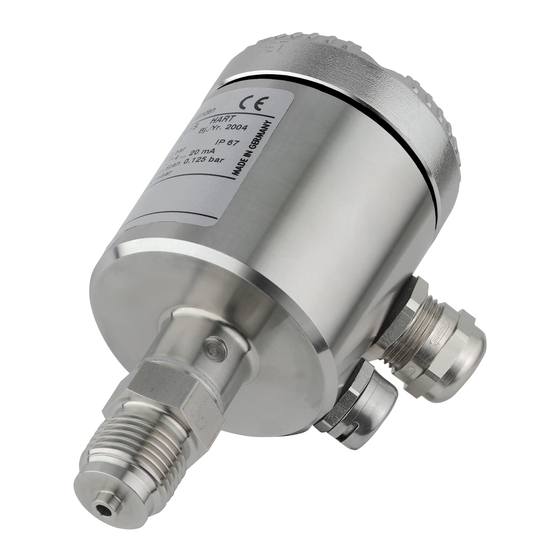
Pressure transmitter
Models 261GS/GC/GG/GJ/GM/GN/GR
Models 261AS/AC/AG/AJ/AM/AN/AR
—
261Gx, 261Ax
Measurement made easy
Additional Information
Additional documentation on 261Gx, 261Ax is
available for download free of charge at
www.abb.com/pressure.
Alternatively simply scan this code:
Advertisement
Table of Contents

Related Manuals for ABB 261GS


Summary of Contents for ABB 261GS
- Page 1 A B B M E A S U R E M E N T & A N A L Y T I C S | O P E R A T I N G I N S T R U C T I O N Pressure transmitter Models 261GS/GC/GG/GJ/GM/GN/GR Models 261AS/AC/AG/AJ/AM/AN/AR Measurement made easy —...
- Page 2 Models 261GS/GC/GG/GJ/GM/GN/GR Models 261AS/AC/AG/AJ/AM/AN/AR Pressure transmitter Operating Instruction IM/261Gx/Ax-EN Rev. 08 Issue date: 11.2018 Original instruction Manufacturer ABB Automation Products GmbH Measurement & Analytics Schillerstr. 72 32425 Minden Germany Tel: +49 57 8 1 30-0 Fax: +49 571 830-1806 Customer service center Tel.: +49 180 5 222 580...
-
Page 3: Table Of Contents
Change from one to two columns Contents Configuration, parameterization ........24 7.1.1 Standard configuration ........24 Safety ................5 Configuration types ..........24 General information and notes for the reader ..5 ... - Page 4 9.3.12 Total performance ..........41 Technical specification ........41 9.4.1 Materials ............41 9.4.2 Calibration ............41 9.4.3 Optional extras ..........41 9.4.4 Process connections ......... 41 ...
-
Page 5: Safety
Safety Improper use The following are considered to be instances of improper use of the device: General information and notes for the reader — For operating as a flexible adapter in piping, e.g. for These instructions are an important part of the product and compensating pipe offsets, pipe vibrations, pipe must be retained for future reference. -
Page 6: Plates And Symbols
Name plate Plates and symbols 1.6.1 Safety / warning symbols, note symbols The warnings in these instructions are structured as follows: DANGER The signal word "DANGER" indicates an imminent danger. Failure to observe this information will result in death or severe injury. -
Page 7: Contents
The CE marking on the device does not refer to the Pressure must observe the following regulations for shipping purposes: Equipment Directive. All devices delivered to ABB must be free from any hazardous The name plate then contains the following identification materials (acids, alkalis, solvents, etc.). -
Page 8: Integrated Management System
This includes the environmentally-friendly use of natural — If it is not possible to dispose of old equipment properly, resources. We conduct an open dialog with the public through ABB Service can take receipt of and dispose of returns for our publications. a fee. -
Page 9: Use In Potentially Explosive Atmospheres
The EC type examination certificates to be communication / configuration / parameterization in a applied are available for download online on the ABB website. potentially explosive atmosphere with type of protection "intrinsic safety", the devices used must be certified Type of protection "intrinsic safety Ex i"... -
Page 10: Function And System Design
Function and system design Operation and system setup The transmitter has a compact design and comprises the pressure measuring cell and electronic unit with pushbutton Digital pressure transmitters are communication-ready field control. Depending on the measuring range and measured devices with microprocessor-controlled electronics. variable, a silicon pressure sensor is used. - Page 11 To measure the output signal and configure / calibrate the pressure transmitter, an ampere meter must be connected directly to the output circuit. The lower and upper range values can be set via a pushbutton on the electronic unit. An optional fastener is available for attaching a stainless steel tag so that the measuring points can be indicated.
-
Page 12: Mounting
Mounting Pressure transmitter The pressure transmitter can be connected directly to the shut-off valve. An angle bracket for wall or pipe mounting (2" Before installing the transmitter, check whether the device pipe) is also available as an accessory. design meets the requirements of the measuring point from a The pressure transmitter should be installed so that the measurement technology and safety specifications point of display and control unit are accessible during installation and... -
Page 13: Sealing And Screw Connections
Sealing and screw connections Moisture Connecting G ½ B spigot: Use suitable cables and tighten cable glands securely. The For sealing, a flat gasket must be used in accordance with DIN transmitter can also be protected against the ingress of EN 837-1. -
Page 14: Measuring Pipe
Measuring pipe In order for the pipes to be laid correctly, the following points must be observed: — Keep the measuring pipe as short as possible and avoid sharp bends. — Lay the measuring pipe in such a way that no deposits can accumulate in it. -
Page 15: Electrical Connections
Electrical connections Cable connection Depending on the model supplied, the electrical connection is established via cable gland M16x1.5 (for diameters of WARNING – Electrical dangers! 5 to 10 mm) or M20x1.5 (for diameters of 6 to 11 mm), a Observe the applicable regulations governing threaded bore for cable gland 1/2-14 NPT, or via the Han 8U electrical installation. -
Page 16: Electrical Connection In The Cable Connection Area
Change from two to one column Electrical connection in the cable connection area Fig. 7 1 Pushbutton for lower/upper range values | 2 + Signal screw terminals for leads with cross-section of 0.5 … 1.5 mm 3 - Signal screw terminals for leads with a cross-section of 0.5 … 1.5 mm | 4 Grounding / equipotential bonding terminal (optional) | 5 Cable entry | 6 Line load | 7 Grounding | 8 Handheld terminal | 9 Resistor (min. -
Page 17: Electrical Connection With Plug
Electrical connection with plug M10691 Fig. 8: Connection via plug connection 1 Harting Han 8D (8U) plug connection | 2 M12 x 1 miniature plug connector Fig. 9: Pin assignment 1 Harting Han 8D (8U) socket insert for mating plug supplied (view of sockets) | 2 Mating plug (socket);... -
Page 18: Assembly And Connection Of Han 8D (8U) Socket Connector
If this value is not achieved within the context of normal installation, an additional resistor must be used. The ABB Contrans I supply modules with HART communication already have a factory-installed, additional resistor. Some of these modules offer the option of Fig. -
Page 19: Connecting Cable
Change from two to one column – – I + FSK 2600T RS 232C M10693 Fig. 11: "Point-to-point" communication mode 1 Pressure transmitter | 2 Possible connecting points for a modem between A and B | 3 Power supply unit | 4 FSK modem 4 &... -
Page 20: Commissioning
Commissioning Output signal If the applied pressure is within the values indicated on the name plate, the output current ranges between 4 und 20 mA. General remarks If the pressure applied falls outside the set range, the output Once the pressure transmitter has been installed, it is put into current will be between 3.5 mA and 4 mA if the range is operation by switching on the operating voltage. -
Page 21: Adjusting Lower Range Value / Oblique Sensor
Adjusting lower range value / oblique sensor Correction procedure "A" described above does not affect the physical pressure shown; it only corrects the analog output During installation of the transmitter, zero position shifts may signal. For this reason, the analog output signal may differ occur due to the mounting position;... -
Page 22: Installing/Removing The Lcd Indicator
Installing/Removing the LCD indicator 3. No tools are required to insert the LCD indicator. Carefully insert both guide pins for the LCD indicator in the guide holes of the transmitter inset. Make sure the black connection socket fits into the terminal on the transmitter inset. -
Page 23: Pressure Sensor Ventilation
Pressure sensor ventilation M10695 Fig. 15: Ventilation unit For technical reasons, you must apply atmospheric pressure to the reference side of the pressure sensor. A special ventilation unit (1) is screwed into the electronic housing from the outside and is equipped with a PTFE filter on the inside. -
Page 24: Configuration, Parameterization
Configuration, parameterization Configuration using pushbutton on pressure transmitter 7.3.1 General remarks NOTICE – Potential damage to device as a The pushbutton is located on the electronics unit (without result of electrostatic charging! mounted LCD indicator). When the housing is open, EMC protection is The pushbutton is used to set the "Lower Range Value"... -
Page 25: Configuration With The Lcd Indicator
Any potential measuring error for the pressure generator Configuration with the LCD indicator should be at least three times smaller than the desired measuring error for the transmitter. IMPORTANT (NOTICE) It is recommended that, if time constant is known, you set the To access the control buttons for the LCD damping to zero (via LCD indicator or graphical user interface). -
Page 26: Process Display
7.4.2 Process display Error messages on the LCD display In the event of an error, a flashing message consisting of an icon and text (e.g., device defective) appears at the bottom of the process display. If you press the left LCD indicator button while a message is flashing, the text becomes permanent. -
Page 27: Menu Structure
Change from two to one column 7.4.4 Menu structure The parameters are structured in the form of a menu. The menu consists of a maximum of three levels. Menu items with an asterisk (*) have additional parameters that are described in the next section. main menu Submenu 1 Submenu 2... -
Page 28: Parameter Descriptions
7.4.5 Parameter descriptions Offset Enabling / disabling (Write Protect) Via LCD indicator, DTM or handheld terminal. If “Write Protect” is enabled, it is not possible to configure the 261G/A pressure transmitter. All editing functions on the indicator are hidden, except for write protection. It is, however, possible to read out data. - Page 29 Damping Installation angle When the output signal for the transmitter is noisy as a result You can specify the extent to which the transmitter deviates of the process, the signal can be smoothed (damped) from the recommended nominal position (vertical, process electrically.
- Page 30 Diagnosis The parameters listed can be displayed temporarily in this view (not failsafe memory). The value configured under “Main operator view” remains unchanged. IMPORTANT (NOTICE) The LCD indicator automatically returns to the process display approximately three minutes after the last button was pressed. HART Tag Each transmitter requires a unique bus ID in order to communicate within a bus structure.
-
Page 31: Configuration With The Graphical User Interface (Dtm)
Configuration with the graphical user interface (DTM) Parameter descriptions 7.5.1 System requirements Write protection — Operating control program (e.g. SMART VISION version Enabling/Disabling is performed via the DTM, handheld 4.01 or higher) terminal or LCD indicator. — DTM or Asset Vision Basic (Device Type Manager, graphic When “Write Protect”... - Page 32 Setting the “Lower Range Value” and “Upper Range Offset Value” Menu path: Menu path: “Configure_Configure Pressure Measurement_Pressure” “Configure_Configure Pressure Measurement_Pressure” This function performs a parallel shift of the characteristic The “Scaling” field offers two setting options. curve so that it travels through a point specified by the user. This makes it possible to set the output signal of several 1.
-
Page 33: Configuration With The Pc / Laptop Or Handheld Terminal
min. 250 Ω Configuration with the PC / laptop or handheld terminal A graphical user interface (DTM) is required for configuration of – – the transmitter via PC or laptop. For operating instructions, I + FSK please refer to the software description. Further information: Data sheet on DTM / SMART VISION or ASSET VISION BASIC Communications protocol:... -
Page 34: Configuration With The Graphical User Interface (Dtm)
Configuration with the graphical user interface (DTM) Parameter descriptions 7.8.1 System requirements Write protection — Operating control program (e.g. SMART VISION version Enabling/Disabling is performed via the DTM, handheld 4.01 or higher) terminal or LCD indicator. — DTM or Asset Vision Basic (Device Type Manager, graphic When “Write Protect”... - Page 35 Setting the “Lower Range Value” and “Upper Range Offset Value” Menu path: Menu path: “Configure_Configure Pressure Measurement_Pressure” “Configure_Configure Pressure Measurement_Pressure” This function performs a parallel shift of the characteristic The “Scaling” field offers two setting options. curve so that it travels through a point specified by the user. This makes it possible to set the output signal of several 1.
-
Page 36: Ex Relevant Specifications
Ex relevant specifications 8.1.2 IECEx transmitter with the following types of protection: ‘Intrinsic Safety ia’, ‘non sparking nA’ and ‘dust ignition protection by enclosure tb’ Hazardous atmospheres 8.1.1 ATEX transmitter with ‘intrinsic safety Ex ia/ib’ type Transmitter with 4 ... 20 mA output signal and HART communication of protection in accordance with Directive Certificate no. -
Page 37: Factory Mutual (Fm)
8.1.3 Factory Mutual (FM) Transmitter with 4 ... 20 mA output signal and HART communication Intrinsic Safety Class I; II and III; Division 1; Groups A, B, C, D; E, F, G Class I; Zone 0; AEx ia Group IIC T6; T4 Non-incendive Class I, II, III, Division 2;... -
Page 38: Specification
9.1.1 Measuring range limits and span limits Sensor code Measuring range upper Measuring range lower Minimum measuring span limit (URL) limit (LRL) Model 261GS Model 261AS Model 261GS Gauge pressure Absolute pressure 6 kPa -6 kPa 0,3 kPa 0,3 kPa... -
Page 39: Operating Limits
9.2.2 Temperature limits °C (°F) Shock resistance Environment Acceleration: 50 g Duration: 11 ms Model 261GS, 261AS Ambient temperature limits (according to 60068-2-27) Operating temperature range -40 … 85 °C (-40 … 185 °F) White oil filling -6 to 85 °C (21 to 185 °F) -
Page 40: Measuring Accuracy
Measuring accuracy 9.3.5 Temperature coefficient (T 9.3.1 Reference conditions according to IEC 60770 Effect of the ambient temperature per 10 K (but limited to the — Ambient temperature TU = constant in the range maximum effect of the temperature change, see previous 18 ... -
Page 41: Total Performance
9.4.2 Calibration 9.3.12 Total performance Standard: Similar to DIN 16086 — 0 to upper range limit (URL) In the range -10 … 60 °C (14 … 140 °F): Optional: 0.42% of the set span (TD 1:1) — To specified measuring span The total performance accuracy includes the measuring error (non-linearity including hysteresis and non-reproducibility), as 9.4.3... -
Page 42: Electrical Connections
9.4.5 Electrical connections M16 x 1.5 tap hole with cable gland (cable diameter approx. 5 … 10 mm), directly on housing M20 x 1.5 (via adapter) with cable gland (cable diameter approx. 6 … 11 mm) 1/2-14 NPT (via adapter) without cable gland Harting Han plug connector (with mating plug (socket outlet, for wire diameters of 0.75 …... -
Page 43: Mounting Dimensions
Change from two to one column Mounting dimensions (not design data) - dimensions in mm (inch) 9.5.1 Standard version Ø 60 (2.36) 15 (0.59) 8 (0.31) Ø 21 (0.83) Ø 28 (1.1) M10684-01 Fig. 24: Dimensions — standard design 1 Electrical connection | 2 Housing cover | 3 Name plate | 4 Filter for atmospheric compensation | 5 Tag (optional) | 6 Process connection | 7 Grounding/equipotential bonding terminal (optional) 1) Clearance for cover removal required 2) With LCD indicator... -
Page 44: Version With The Options "Lcd Indicator" And "Harting Han Plug
9.5.2 Version with the options “LCD indicator” and “Harting Han plug” Ø 60 (2.36) 102 (4.02) Ø 21 (0.83) Ø 28 (2.13) M10685-01 Fig. 25: Dimensions — with options 1 Housing cover for LCD indicator option Dimensions for sensor code C, F Dimension "A"... -
Page 45: Transmitter With Flush Diaphragm
9.5.3 Transmitter with flush diaphragm Fig. 26: Dimensions - With flush diaphragm 1 Welded connections / tapped hole for flush diaphragm, part no. 284903 | 2 No burrs | 3 Groove for gasket DIN 3869 - 21 18.5 x 23.9 x 1.5 | 4 Groove for O-ring 15 x 2 Bevel after cutting threads Minimum dimension Wrench size 27... -
Page 46: Version With Ball Valve Connection
9.5.4 Version with ball valve connection Fig. 27: Dimensions - With ball valve connection 1 Shim | 2 Diaphragm diameter: ~ 20 mm (0.79 inch) | 3 metal / metal conical seal, diaphragm is process-bonded | 4 Weld-in sleeve G 1", part no.: 789516 Wrench size 36 46 IM/261Gx/Ax-EN Rev. -
Page 47: Mounting With Angle Bracket (Optional)
9.5.5 Mounting with angle bracket (optional) 12,5 (0.49) (0.59) 72 (2.83) 72 (2.83) (0.79) M10688-01 Fig. 28: Dimensions — pipe mounting/wall mounting 1) Dimensions for sensor code C, F 2) Sensor code L, D, U, 1, R, V IMPORTANT (NOTICE) The bracket for wall or pipe mounting has four holes with a Ø... -
Page 48: Maintenance / Repair
10 Maintenance / Repair 10.1 Removal WARNING – Potential danger if device is WARNING disassembled incorrectly! Bodily injury! Before removing or disassembling the device, The device can be operated at high pressure and with check for hazardous process conditions such as aggressive media. -
Page 49: Appendix
Designation relating to intended use in potentially explosive atmospheres in compliance with: protection — ATEX Directive (additional identification with CE mark) NOTICE All documentation, declarations of conformity, and certificates are available in ABB's download area. www.abb.com/pressure 261Gx, 261Ax | IM/261Gx/Ax-EN Rev. 08 49... - Page 50 Statement on the contamination of devices and components Repair and / or maintenance work will only be performed on devices and components if a statement form has been completed and submitted. Otherwise, the device / component returned may be rejected. This statement form may only be completed and signed by authorized specialist personnel employed by the operator.
- Page 51 Notizen 261Gx, 261Ax | IM/261Gx/Ax-EN Rev. 08 51...
- Page 52 We reserve the right to make technical changes or modify the contents of this document without prior notice. With regard to purchase orders, the agreed particulars shall prevail. ABB does not accept any responsibility whatsoever for potential errors or possible lack of information in this document.