
Related Manuals for Toro Topdresser 2500


Summary of Contents for Toro Topdresser 2500
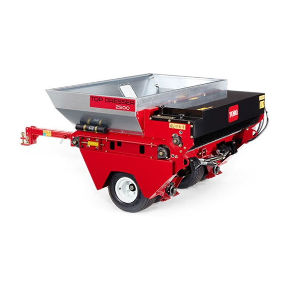
- Page 1 Form No. 3429-188 Rev A Topdresser 2500 Model No. 44507—Serial No. 403420001 and Up *3429-188* A Register at www.Toro.com. Original Instructions (EN)
- Page 2 Whenever you need service, genuine Toro parts, or additional information, contact an Authorized Service Dealer or Toro Customer Service and have the model and serial numbers of your product ready. Figure 1 identifies the location of the model and serial numbers on the product.
-
Page 3: Table Of Contents
Contents Hydraulic Fluid Specifications......27 Checking the Hydraulic Fluid Level ....28 Replacing the Hydraulic Filter ......28 Safety ............... 4 Changing the Hydraulic Fluid ......29 General Safety ........... 4 Brush Maintenance ..........30 Safety and Instructional Decals ......4 Checking the Brush for Position and Setup ................ -
Page 4: Safety
Safety • Do not operate the machine without all guards and other safety protective devices in place and functioning properly on the machine. General Safety • Keep bystanders and children out of the operating area. Never allow children to operate the machine. This product is capable of amputating hands and feet and of throwing objects. - Page 5 decal99-0016 99-0016 1. Warning—read the Operator's Manual; the maximum braking load is 1,587 kg (3,500 lb); the maximum tongue weight is 181 kg (400 lb); do not drive the vehicle with a trailer down a hill; do not lose control of the vehicle and trailer. 2.
- Page 6 decal138-5941 138-5941 1. Crushing hazard of hand—keep bystanders away. decal138-5949 138-5949 1. Warning—read the 2. Warning—receive training Operator's Manual. before operating the machine.
-
Page 7: Setup
Setup Loose Parts Use the chart below to verify that all parts have been shipped. Procedure Description Qty. Tongue assembly Lynch pin Install the tongue. Clevis pin Assemble the hitch to the traction-unit – No parts required drawbar. Jack (optional) Mount optional tongue jack. -
Page 8: Assembling The Hitch To The Traction-Unit Drawbar
g269296 Figure 5 1. Locknut 5. Hairpin 2. Washer 6. Hitch pin 3. Tongue 7. Hitch clevis 4. Capscrew g269254 Figure 4 Assemble the hitch clevis to the tongue with the 2 capscrews, 4 washers, and 2 locknuts (Figure 1. Back of the machine 3. -
Page 9: Installing The Wire Harness
g280872 Figure 6 1. Jack-mount tube (tongue) 2. Jack g012647 Figure 7 Align holes in jack with holes in the mounting tube and secure the jack with the clevis pin 1. Topdresser harness 3. Tow-vehicle harness (Figure 2. Controller harness Route the ring terminals of the tow-vehicle harness to battery of the traction unit. -
Page 10: Mounting The Skids
Mounting the Skids Parts needed for this procedure: Skid Carriage bolt Flat washer Locknut Procedure Position skid as shown in Figure g012648 Figure 8 1. Skid (4) Mount a skid to the mounting bracket with 2 carriage bolts, 2 flat washers and 2 locknuts. Repeat steps for the skids at the 3 other mounting brackets. -
Page 11: Product Overview
Hand Control Switch Product Overview Press hand control switch to start or stop the flow of material from topdresser (Figure 10). Controls Gate Metering Control g269331 g266287 Figure 10 Figure 9 1. Hand control switch 1. Adjusting handle 3. Rate scale 2. -
Page 12: Specifications
Authorized Service Dealer or authorized Toro • Do not modify this equipment in any manner. distributor or go to www.Toro.com for a list of all • The tongue is the area on the machine where the approved attachments and accessories. -
Page 13: Special Instructions For Workman And Other Traction Units
• – When the weight of the tongue is forced down Keep your hands and feet out of the hopper. onto the hitch of the tow vehicle, this produces • Remain seated whenever the vehicle is in motion. a positive tongue weight. •... - Page 14 Slope Safety – Do not leave the machine unattended while the tow vehicle is running. • Review the vehicle specifications to ensure that • Ensure that the machine is connected to the tow you do not exceed its slope capabilities. vehicle before loading.
-
Page 15: Supporting The Machine With The Optional Jack
Supporting the Machine Operating the Machine with the Optional Jack Important: Always read and understand the operator's manual for the traction unit before Use the jack when the you remove the machine from using the machine. the traction unit. Start the traction unit; refer to the traction unit Remove the clevis pin. -
Page 16: Sand Application Rate
Preparing for Cold Weather to tip-overs. Use caution when transporting or topdressing with a full load. Operation • Heavy loads increase stopping distance and reduce your ability to turn quickly without tipping Although limited by the traction of the drive tires, you over. -
Page 17: Operating Tips
Operating Tips inclines, or grades whenever possible. Do not drive across the face of a slope if possible. • The topdresser material application system is There is a risk of overturning the machine, ground driven, so you need to tow the machine to which can result in serious injury or death. -
Page 18: After Operation
13 kph (8 mph) tow speed. This the operating instructions in the Toro Workman or machine was not designed for travel on highways. other traction unit operator's manual before using Towing the machine faster than 24 kph (15 mph) the topdresser. -
Page 19: Maintenance
To ensure safe, optimal performance of the • Perform only those maintenance instructions machine, use only genuine Toro replacement described in this manual. If major repairs are parts. Replacement parts made by other ever needed or assistance is desired, contact an manufacturers could be dangerous, and such use authorized Toro distributor. -
Page 20: Pre-Maintenance Procedures
Pre-Maintenance Lubrication Procedures Grease Specification Preparing for Maintenance No. 2 lithium grease Shut off the hand-control switch for the Greasing the Bearings and topdresser. Move the machine to a level surface. Bushings Set the parking brake of the traction unit, shut Service Interval: Every 200 hours/Yearly (whichever off the engine, remove the key, and wait for comes first) -
Page 21: Drive System Maintenance
Drive System Maintenance Checking the Tire Air Pressure Service Interval: Before each use or daily Perform the steps in Preparing for Maintenance g012653 (page 20). Figure 16 Check the tire air pressure. You should measure 138 to 207 kPa (20 to 30 Note: Do not lubricate the drive chains unless they psi) air pressure. -
Page 22: Tensioning The Conveyor-Belt Chain
Rotate motor sprocket assembly (Figure 17) until the wheel-drive chain deflects 3.2 mm (1/8 inch). Note: Access to chain is through cutout in lower side of axle cradle. Important: Do not overtension the chain or it will wear prematurely. Do not under-tension the chain or it will cause sprocket wear. -
Page 23: Belt Maintenance
Belt Maintenance Tensioning the Conveyor Belt When conveyor belt is adjusted properly, the compressed length of each compression spring should be 112 mm (4-7/16 inches). Adjust conveyor g012663 Figure 21 belt as follows: 1. Belt-roller shafts 2. 895 mm (35-1/4 inches) Empty the hopper. - Page 24 Removing the Conveyer Chain Disassembling the Slider Bed Remove chain cover (Figure 23). Loosen forward and rear jam nuts on tension rod to release spring tension (Figure 25). g012667 Figure 25 1. Tension rods 2. Jam nut g012659 Figure 23 At each side of machine, remove 2 capscrews, 2 1.
- Page 25 g012671 Figure 29 1. Lifting rod 2. Capscrews (slider-frame rail) g012669 Figure 27 Removing the Belt At the right side of machine, loosen 2 capscrews Cut belt and remove it from rollers. that secure slider-frame rail to the right fender (Figure 28).
- Page 26 Assembling the Slider Bed At the left side of machine, assemble the slider-frame rail to the left fender (Figure with the 2 capscrews and 2 washers that you removed in Disassembling the Slider Bed (page 24), and tighten the capscrews. g012668 Figure 32 Right side shown...
-
Page 27: Hydraulic System Maintenance
A machine using the recommended replacement fluid requires less frequent fluid and filter changes. Alternative hydraulic fluids: If Toro PX Extended Life Hydraulic Fluid is not available, you may use another conventional, petroleum-based hydraulic fluid having specifications that fall within the listed range for all the following material properties and that it meets industry standards. -
Page 28: Checking The Hydraulic Fluid Level
This fluid is compatible with the elastomers used in filler neck (Figure 35). in Toro hydraulic systems and is suitable for a If level is low, add the specified hydraulic fluid wide-range of temperature conditions. This fluid is to raise level. -
Page 29: Changing The Hydraulic Fluid
Add approximately 9.5 L (2.5 US gallon) of the Important: If fluid becomes contaminated, specified hydraulic fluid; refer to Hydraulic Fluid contact your authorized Toro distributor because Specifications (page 27). you must drain the complete hydraulic system. Contaminated fluid looks milky or black when... -
Page 30: Brush Maintenance
Brush Maintenance Checking the Brush for Position and Wear Service Interval: Every 40 hours Brush must make enough contact with conveyor belt to disperse top-dressing material but not restrict the rotation of the brush. A piece of stiff paper can be inserted between the conveyor belt and the brush to g012658 check the adjustment. -
Page 31: Cleaning
Cleaning Storage Storage Safety Washing the Machine • Shut off the machine, remove the key (if equipped), • Thoroughly clean the machine, especially inside and wait for all movement to stop before you leave the hopper. Clean the hopper and conveyor belt the operator’s position. -
Page 32: Troubleshooting
1. The traction unit has the wrong 1. Purchase an additional harness from disconnect. connector. your authorized Toro distributor. 2. The on/off connections are switched 2. Correct the connections. with brake wiring. The topdresser is hard to pull with the 1. -
Page 33: Schematics
Schematics g280721 Hydraulic Schematic 138-5972 (Rev. A) - Page 34 g269551 Electrical Schematic 100-7687 (Rev. A)
- Page 35 Notes:...
- Page 36 Notes:...
- Page 37 Notes:...
- Page 38 The Toro Company (“Toro”) respects your privacy. When you purchase our products, we may collect certain personal information about you, either directly from you or through your local Toro company or dealer. Toro uses this information to fulfil contractual obligations - such as to register your warranty, process your warranty claim or to contact you in the event of a product recall - and for legitimate business purposes - such as to gauge customer satisfaction, improve our products or provide you with product information which may be of interest.
- Page 39 While the exposure from Toro products may be negligible or well within the “no significant risk” range, out of an abundance of caution, Toro has elected to provide the Prop 65 warnings. Moreover, if Toro does not provide these warnings, it could be sued by the State of California or by private parties seeking to enforce Prop 65 and subject to substantial penalties.
- Page 40 Countries Other than the United States or Canada Customers who have purchased Toro products exported from the United States or Canada should contact their Toro Distributor (Dealer) to obtain guarantee policies for your country, province, or state. If for any reason you are dissatisfied with your Distributor's service or have difficulty obtaining guarantee information, contact your Authorized Toro Service Center.