Table of Contents
Advertisement
Quick Links
Download this manual
See also:
User Manual
Advertisement
Chapters
Table of Contents

Related Manuals for ABB PowerValue 11/31 T


Summary of Contents for ABB PowerValue 11/31 T
- Page 1 _________ l � -' -------- - - ИБП ABB Powervalue 11/31 T (10, 20 кВА) - руководство по эксплуатации. Юниджет Постоянная ссылка на страницу: https://www.uni-jet.com/catalog/istochniki- besperebojnogo-pitaniya/on-line-ibp-10-100-kva/abb-powervalue-11-31.html...
- Page 2 Operating manual PowerValue 11/31 T 10 kVA, 10 kVA B, 10 kVA B2, 10 kVA S 20 kVA, 20 kVA B, 20 kVA S © Copyright 2017 ABB, All rights reserved...
- Page 4 Document information File name 4NWP100559R0001_OPM_ABB_PVA11-31-T_10-20kVA_EN_REV-C.docx : PowerValue 11/31 T UPS model Date of issue : 01.12.2016 Article number : 4NWP100559R0001 Document number : 4NWD003235 Revision Foreword The UPS system operates with mains, battery or bypass power. It contains components that carry high currents and voltages.
- Page 5 Symbols The following symbols are used in this manual, the list below describes each symbol. SEVERE INJURY AND/OR SERIOUS DAMAGE TO THE SYSTEM WILL WARNING RESULT IF PROPER PRECAUTIONS ARE NOT TAKEN MINOR INJURY AND/OR DAMAGE TO THE PRODUCT MAY RESULT IF CAUTION PROPER PREACAUTIONS ARE NOT TAKEN NOTE...
-
Page 6: Table Of Contents
Contents Safety instructions ................. 7 1.1 Operator precautions ..................7 1.2 Environmental Considerations ................ 8 1.3 Declaration of Safety conformity and CE marking ......... 8 1.4 Inquiries ......................8 1.5 Operation ......................9 Maintenance ..................11 2.1 Battery Recycling ..................13 General Characteristics ............... - Page 7 Operation ..................... 28 5.1 Control Panel ....................28 5.1.1 LEDs .......................... 28 5.1.2 Selection Keys ......................29 5.1.3 LCD Display ......................29 5.2 Operating Mode .....................30 5.3 UPS Start-up and Shutdown .................31 5.3.1 UPS start-up ......................31 5.3.2 UPS Shutdown ......................32 5.3.3 Parallel UPS system ....................
-
Page 8: Safety Instructions
Safety instructions 1.1 Operator precautions The user must follow the precautions and only perform the described operations. Also in these measures, the operator of the UPS System must adhere to the instructions in this manual. Any deviations from the instructions could be dangerous to the user or cause accidental load loss. The only user operations permitted are: •... -
Page 9: Environmental Considerations
1.2 Environmental Considerations To operate the UPS at the best efficiency point, your installation site should meet the environmental parameters outlined in this manual. Excessive amount of dust or moisture in the operating environment may cause damage or lead to malfunction. The UPS should be always protected from the outside weather and sunshine. -
Page 10: Operation
1.5 Operation DANGER! DO NOT REMOVE THE ENCLOSURE OF THE UPS WARNING! EARTH CONNECTION IS ESSENTIAL BEFORE CONNECTING TO THE BUILDING-WIRING TERMINAL CAUTION! DO NOT DISCONNECT THE MAINS CABLE FROM THE UPS OR THE BUILDING WIRING SOCKET DURING OPERATION AS THIS WOULD REMOVE THE GROUND TO THE UPS AND OF ALL CONNECTED LOADS. - Page 11 TO DISCONNECT COMPLETELY THE UPS, FOLLOW THE INSTRUCTIONS IN SECTION 5.3.2 NOTE! INDISCRIMINATE OPERATION OF SWITCHES MAY CAUSE OUTPUT LOSS OR DAMAGE TO EQUIPMENT CAUTION! ENSURE THAT NO LIQUID OR OTHER FOREIGN OBJECTS ENTER THE UPS WARNING! Modifications reserved Page 10/49...
-
Page 12: Maintenance
Maintenance PLEASE REFER TO YOUR AUTHORIZED SERVICE PARTNER FOR THE RECOMMENDED MAINTENANCE PLAN (INCLUDING THE SPECIFIC SCHEDULED REPLACEMENT OF FANS). PERFORMING REGULAR AND PREVENTIVE MAINTENANCE NOT ONLY KEEPS THE PERFORMANCE STABLE AND EXTENDS THE LIFE OF THE EQUIPMENT, BUT ALSO DECREASES THE RISK OF FAILURE. - Page 13 THE BATTERY CIRCUIT IS NOT ISOLATED FROM THE INPUT VOLTAGE. DANGER! HAZARDOUS VOLTAGES MAY OCCUR BETWEEN THE BATTERY TERMINALS AND THE GROUND. VERIFY THAT NO VOLTAGE IS PRESENT BEFORE SERVICING WARNING! A BATTERY CAN PRESENT A RISK OF ELECTRICAL SHOCK AND HIGH SHORT CIRCUIT CURRENT.
-
Page 14: Battery Recycling
If the battery service life (3~5 years at 25°C ambient temperature) has been exceeded, the batteries must be replaced. In this case please contact your dealer. The UPS should be charged once every 4 to 6 months if it has not been used for a long time. The batteries charge to 90% capacity in approximately 4 hours. -
Page 15: General Characteristics
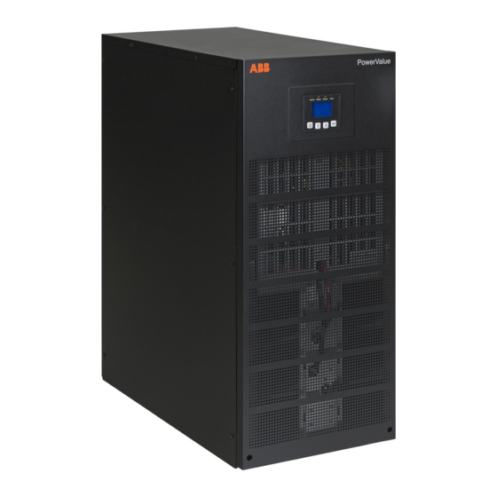
3.1 UPS front view Number Description LCD display LEDs Control keys Ventilation inlets Wheels UPS support Figure 2: Front view of PowerValue 11/31 T 10-20 kVA 3.2 UPS rear view Number Description 10 kVA 20 kVA Terminal blocks Input breaker Back feed control... -
Page 16: External Battery Cabinet Front View
3.3 External battery cabinet front view Number Description Ventilation inlets Wheels UPS support Figure 4: Front view of external battery cabinet 3.4 External battery cabinet rear view Number Description Ventilation inlets Fuse holder Connection terminals Wheels UPS support Figure 5: Rear view of external battery cabinet Modifications reserved Page 15/49... -
Page 17: Installation
Installation 4.1 Delivery, Transportation, Positioning and Storage 4.1.1 Receipt of the UPS and visual inspection Upon receiving the UPS, carefully examine the packing container and the UPS for any sign of physical damage. In case of damage, notify immediately the carrier. The packing container of the UPS protects it from mechanical and environmental damage. -
Page 18: Ups Storage
Examine the UPS for any sign of damage and ensure that the received UPS corresponds to the material indicated in the delivery note. Notify your carrier or supplier immediately if damage is apparent. The content of the package is: - 1 x PowerValue 11/31 T UPS - 1 x User manual - 1 x parallel cable... -
Page 19: Electrical Installation
4.2 Electrical Installation 4.2.1 Commissioning The UPS must be commissioned by a fully trained and authorized field service engineer before being put into use. The commissioning of the UPS involves the connection of the UPS and batteries, the verification of the electrical installation and operating environment of the UPS, the controlled start-up and testing of the UPS and customer training. -
Page 20: Procedure
4.2.2.1 Procedure 2. Remove the protective plates of the cable 1. Open the terminal block cover located entries (the bypass hole should remain closed on the rear panel of the UPS. for safety purposes if it is not used) Protective plates 3. - Page 21 Single phase input – single phase output (11) Single Input Feed 1. Connect the neutral cable to the neutral terminal of mains 2. Note that the mains neutral is connected internally in the UPS. For this, there is no need to connect the neutral cable to the mains 1 terminal.
- Page 22 Dual Input Feed 1. Connect the neutral cable to the neutral terminal (mains 1 and mains 2). 2. Connect the 3 pin connector provided with the UPS between terminals L1, L2 and L3. Terminal block cover 3 PIN for connecting L1,L2,L3 Figure 9: 3 pin connector installation 3.
- Page 23 Three phase input – single phase output (31) Single Input Feed 1. Connect the neutral cable to the neutral terminal (main 2). Note that the mains neutral is connected internally in the UPS. For this, there is no need to connect the neutral cable to the mains 1 terminal. 2.
-
Page 24: Parallel System Cabling
Figure 13: Dual feed (31) wiring diagram DO NOT CONNECT EQUIPMENT THAT COULD OVERLOAD THE UPS SYSTEM (E.G. LASER PRINTERS) CAUTION! 4.2.2.2 Parallel system cabling 1. Prepare the input and output wires, the output breaker, and the parallel cable according to section Error! Reference source not found.. - Page 25 Figure 14: Terminal block wiring diagram in parallel configuration Figure 15: Parallel Installation Diagram To add or to remove a UPS to an existing system, go to section 5.3.3 Modifications reserved Page 24/49...
-
Page 26: Batteries
4.3.1 In-built batteries Some models of PowerValue 11/31 T have internal batteries. These batteries are already installed and connected when the units are delivered. To replace, reduce or increase the amount of batteries, connect the batteries as indicated in the figure 16. Connect the terminals to their matching color terminals. -
Page 27: Backfeed Protection
AFTER CONNECTING THE BATTERY CABINET, CONFIGURE THE NUMBER OF BATTERY MODULES IN THE CONTROL PANEL (REFER TO SECTION 5.4.2.5). SEE APPENDIX C FOR FURTHER DETAILS NOTE! REFER TO BATTERY CABINET FOR POWERVALUE 11/31 T USER MANUAL FOR FURTHER INFORMATION NOTE! 4.4 Backfeed Protection To support protection against UPS back feed currents, an additional external isolation device must be installed in the bypass path according to the figure below. -
Page 28: Emergency Power Off (Epo)
4.5 Emergency Power Off (EPO) The EPO connector gives the user the possibility to block the output of the UPS in case of an emergency. As a default, the EPO is Normally Closed (NC) by a jumper in the rear panel. If the jumper is removed, the UPS output will not supply energy to the load until the EPO status is again modified. -
Page 29: Operation
Operation This chapter describes how to operate the UPS through the LCD display. User possible operations are: • Operate the LCD display • Start up and shut down of the UPS of the user field (excluding the commissioning start up) Operation of additional SNMP adapters and their software 5.1 Control Panel The user-friendly control panel is composed of LEDs, an LCD display and four selection keys. -
Page 30: Selection Keys
5.1.2 Selection Keys The Button Function Illustration Power On/Off Turn on and off the UPS or change operating mode. Scroll up Enter/Exit the menus and scroll across the screens. Scroll down Scroll down the menu Select / Edit Select and confirm settings. To see how to operate the UPS, go to Section 5.4. -
Page 31: Operating Mode
5.2 Operating Mode Different symbols indicate the status and the operating mode of the UPS. Such symbols appear always in the position indicated in Figure 20. Figure 20: Operating mode Status Symbol Description Online-mode UPS is running through the inverter (Online-mode) Battery-mode UPS running on battery. -
Page 32: Ups Start-Up And Shutdown
In situations of failure, the UPS may disconnect the load or transfer to bypass depending on the cause of the failure. In all cases, there Fault will be a constant alarm and the backlight of the UPS will become red. See Section 7 for details. When the UPS is in overload, unnecessary loads should be disconnected one by one to decrease the load. -
Page 33: Ups Shutdown
5.3.2 UPS Shutdown With mains supply 1. If the UPS is working on bypass-mode, go to step 3. 2. If the UPS is on online-mode, press the power-on button continuously for more than 3s. The alarm buzzer will sound and the UPS will transfer to bypass-mode. Note: the output is still energized. 3. - Page 34 4. Set the own maintenance switch of each UPS from “UPS” to “BPS”. 5. Switch off the main output breaker and the main input breaker. The UPS will shut down. 6. Check that that there is no current in the output and that the UPS is switched off. 7.
-
Page 35: Ups Operation
5.4 UPS Operation Information regarding the status of the UPS, measurements, events and general information on the UPS are available through the LCD display. This chapter describes how to navigate through the display and how to adjust the user’s settings. 5.4.1 Changing the operating-mode To change the operating-mode, the power-on button is used as follows:... -
Page 36: Event Log
5.4.2.1 Event log To enter this menu, press . In this menu, the last 50 events, alarms and faults occurred in the UPS are displayed. The alarms are indicated by the corresponding event code and operating time of UPS when the event occurred. To navigate through the events and alarms, press or . -
Page 37: Identification
Figure 22: Control menu tree 5.4.2.4 Identification Press on the Identification menu to navigate through its data. The identification information includes UPS serial number, firmware serial number and model type. Press for more than 1s to return to the last main menu. Figure 23: Identification menu tree 5.4.2.5 User’s Settings Some settings can impact on the performance of the UPS and others can enable and disable functions... - Page 38 To modify a parameter, press for less than 1 second and scroll up or down. To confirm the selection press this same button for more than 1 second. Figure 24: Setting menu tree USER If the password is enabled, the user must enter the password by pressing the buttons , .
- Page 39 The automatic bypass can be disabled for countries where the power supply is Auto bypass enabled/disabled disabled very unstable. UPS runs only online or on battery. - When enabled, short circuit will last for 4s before cutting off the output. If short circuit is removed during this time, the Short circuit UPS will continue to run normally.
-
Page 40: Communication
Figure 25: Setting rated output voltage value Communication A USB and an RS-232 port are available to enable the communication between the UPS and a remote computer/station. Only one communication port can be active at a time and the priority is given to the USB port. -
Page 41: Network Management Card (Optional)
USB 1.1 protocol. 6.3 Network Management Card (Optional) PowerValue 11/31 T is equipped with two intelligent slots for optional cards for remote management of the UPS through internet / intranet. The accessories below can be installed in any of the intelligent slots. -
Page 42: As400 Dry Contact Card
6.3.3 Monitoring Software ABB UPS can be monitored through a software that allows the user to monitor the UPS. The software provides a remote and safe shutdown for multi-client systems in case of absence of power in the output of the UPS. Instructions on how to install the software are provided with the network management cards. -
Page 43: Troubleshooting
Troubleshooting 7.1 Fault identification and rectification Alarm and events identify warning situations and notify errors or potential failures of the system. The output of the UPS is not necessarily affected in case of an alarm but taking the correct actions may prevent loss of power to the load. - Page 44 Heat sink Over Inside temperature Ensure the UPS is not overloaded, the of UPS is too high Temperature Fault air vents are not blocked and the ambient temperature is not too high. Alarm code:81 Wait for 10 minutes for the UPS to cool down before turning it on again.
-
Page 45: Appendix A
Appendix A CS141 SNMP card available parameters (valid for CS141 Basic, CS141 ModBus, CS141 Advanced) The parameters available from CS141 SNMP cards are herein described Parameter Units Type Available interface Modbus register Measurement Parameters Input Webserver / Modbus Input Voltage Input Frequency Input Webserver / Modbus... -
Page 46: Appendix B
Appendix B Winpower SNMP card available parameters (webserver interface) The parameters available from Winpower SNMP cards are herein described Parameter Type View UPS Status General, status UPS Monitoring >> UPS Status UPS Temperature General, measurement UPS Monitoring >> UPS Status Voltage Input, measurement UPS Monitoring >>... -
Page 47: Appendix C
UPS Model Battery configuration UPS PowerValue 11/31 T 10 kVA no internal UPS PowerValue 11/31 T 10 kVA B 1 x ( 24 x 9Ah ) UPS PowerValue 11/31 T 10 kVA B2 2 x ( 24 x 9Ah ) - Page 48 (USER)External battery SASV03[value]<cr> modules) UPS PowerValue 11/31 T 10 kVA N/9 – 1 UPS PowerValue 11/31 T 10 kVA B N/9 + 1 UPS PowerValue 11/31 T 10 kVA B2 N/9 + 1 N/9 + 2 UPS PowerValue 11/31 T 20 kVA N/9 –...
- Page 49 Contact us www.abb.com/ups © Copyright ABB. All rights reserved. Specification ups.sales@ch.abb.com subjects to change without notice.
- Page 50 93% Efficiency in ECO-MODE up to 97% Maximum weight w/out batteries 66.8 kg Input current distortion THDI <5 % Input power factor (PF) 0.99 Communication cards SNMP / relay card © Copyright 2017 ABB, All rights reserved. ...
- Page 51 Input characteristics ..........................7 Output characteristics ........................... 8 Battery characteristics........................... 9 User interface ............................10 Display & mimic diagram ........................10 Clearances ............................11 Cables & fuses ............................ 12 Ratings ............................... 12 PowerValue 11/31 T Technical Specifications Page 2 ...
-
Page 52: Ups Features
Activating the emergency power off Paralleling control of the UPS, the AC and the PowerValue 11/31 T 10 and 20 kVA DC sources to the load are entirely UPS can be installed in parallel to To connect several battery cabinets disconnected. -
Page 53: Batteries
25 / 50 / 75 / 100% load Given runtimes are estimates and valid at 20 degrees Celsius. Actual runtime of the system will depend, among many variables, on the age of the batteries and environmental conditions PowerValue 11/31 T Technical Specifications Page 4... -
Page 54: Ups Devices
Control keys Ventilation inlets Connection terminals Input breaker Back feed protection terminals Fans Network interface / AS400 slot EPO contact RS232 port / USB port Parallel port Wheels / support and brakes Maintenance switch PowerValue 11/31 T Technical Specifications Page 5... -
Page 55: Options
Temperature sensors, humidity sensors and alarm buzzers support monitoring the environmental condition and enables an efficient identification of the alarms. Relay interface card Provides contact closures for remote monitoring of alarm conditions of PowerValue 11/31 T systems. The card is user-installable, hot-swappable and enables advanced communication between the UPS and the computer. Models ... -
Page 56: Technical Specifications
10 kVA 20 kVA Rated voltage 1ph + N: 220 / 230 / 240 VAC 3ph + N: 380 / 400 / 415 VAC (steady-state, r.m.s) 50 Hz / 60 Hz (selectable) Frequency, rated PowerValue 11/31 T Technical Specifications Page 7... -
Page 57: Output Characteristics
50 / 60 Hz (selectable) Variation in normal and battery Max ± 10% mode Variation in free-running ± 0.05 Hz Max synch phase error ≤3° (referred to a 360° cycle) Max slew-rate 1 Hz/s PowerValue 11/31 T Technical Specifications Page 8... -
Page 58: Battery Characteristics
1.65 VDC voltage (VRLA) R.m.s. ripple current ±2% (% of the battery capacity ) Temperature compensation Battery test Automatic and periodic battery test (selectable) 1) With recommended fuses, see section Cables and Fuses PowerValue 11/31 T Technical Specifications Page 9... -
Page 59: User Interface
Dot matrix 128x64 LCD display + 4 LEDs OPTIONAL ITEMS SNMP card For monitoring and integration in network management Relay card For additional signal-monitoring and control DISPLAY & MIMIC DIAGRAM 10 kVA PowerValue 11/31 T Technical Specifications Page 10 ... -
Page 60: Clearances
669 W / 2282.7 BTU 1207 W / 4118.5 BTU non-lin. load (acc. to 62040-3) Air-flow (25° - 30°) with 100% 133 m 240 m non-linear load Heat Dissipation without load 160 W 170 W PowerValue 11/31 T Technical Specifications Page 11... - Page 61 Battery fuse E-Type: gR or CB 2 x 40A 2 x 40A 2 x 80A 2 x 80A Battery cable E 3 x 6mm 3 x 6mm 3 x 16mm 3 x 16mm PowerValue 11/31 T Technical Specifications Page 12 ...
- Page 62 Contact us © Copyright ABB. All rights reserved. www.abb.com/ups Specifications subject to change ups.sales@ch.abb.com without notice...