Table of Contents
Advertisement
Quick Links
Advertisement
Table of Contents

Related Manuals for ABB TLE Scalable Series


Summary of Contents for ABB TLE Scalable Series
- Page 1 — UPS INSTALLATION GUIDE TLE Scalable Series 40 to 150 kVA UL S1...
- Page 2 The present publication and any other documentation supplied with the UPS system is not to be reproduced, either in part or in its entirety, without the prior written consent of ABB. The illustrations and plans describing the equipment are intended as general reference only and are not necessarily complete in every detail.
- Page 3 We thank you for selecting our products and are pleased to count you amongst our very valued customers at ABB. We trust that the use of the TLE Scalable Series 40 to 150 Uninterruptible Power Supply System, developed and produced to the highest standards of quality, will give you complete satisfaction.
- Page 4 While every care has been taken to ensure the completeness and accuracy of this manual, ABB assumes no responsibility or liability for any losses or damages resulting from the use of the information contained in this document.
-
Page 5: Table Of Contents
4.8.3 Battery cabinet connection to TLE Scalable Series 40 to 150 ..............35 4.8.4 Use of TLE Scalable Series 40 to 150 in SEM Operation Mode (Super Eco Mode) ......37 4.8.5 Use of TLE Scalable Series 40 to 150 as Frequency Converter .............. 38 RPA Parallel System connection .......................... -
Page 6: Safety Rules
UPS Installation Guide / REV-B Safety rules Save these instructions! This manual contains important instructions for models TLE Scalable Series 40 to 150 that should be followed during installation and maintenance of the UPS and Battery. General Move the UPS in an upright position in its original package to the final destination room. - Page 7 7/54 TLE Scalable Series 40 to 150 UL S1 UPS Installation Guide / REV-B Safety instructions when working with Battery Danger! External Battery must be installed and connected to the UPS by Qualified Service Personnel. Installation Personnel must read this entire section before handling the UPS and Battery.
-
Page 8: Safety Symbols And Warnings
8/54 TLE Scalable Series 40 to 150 UL S1 UPS Installation Guide / REV-B 1.1 Safety symbols and warnings Safety warnings The text of this manual contains some warnings to avoid risk to the persons and to avoid damages to the UPS system and the supplied critical loads. -
Page 9: Layout
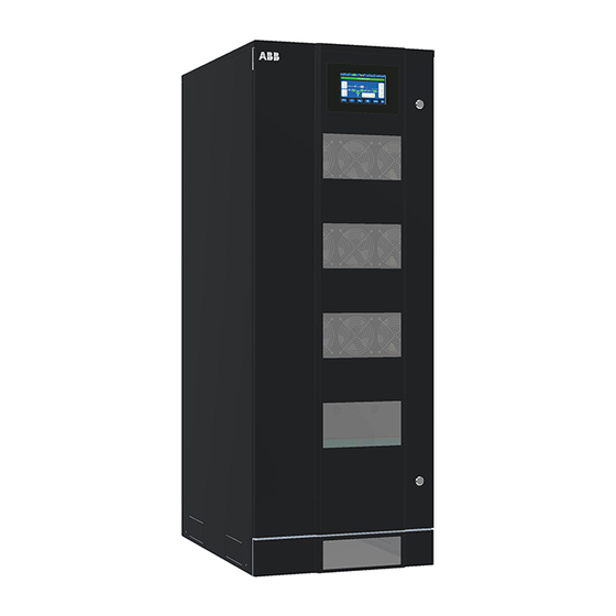
Fig. 2.1-2 Control panel Fig. 2.1-3 Q1 - UPS Output switch Connectivity Slots CONN2 J35µP - RS232 CONN3 CONN4 SNMP Card Customer InterfaceI board board Fig. 2.1-1 TLE Scalable Series 40 to 150 - General view SNMP UVR (option) Fig. 2.1-4 Connectivity Slots... - Page 10 (see Fig. 2.1-4) Terminals (Emergency Power Off) and 24Vdc connection Remove this panel or provide means to capture metal filings from cutting conduit entry holes Fig. 2.1-8 TLE Scalable Series 40 to 150 - General front view without protection panels...
-
Page 11: Environment
UPS packing materials must be recycled in compliance with all applicable regulations. Recycling at the end of service life! ABB, in compliance with environment protection recommends to the User that the UPS equipment, at the end of its service life, must be recovered conforming to the local applicable regulations. -
Page 12: Installation
12/54 TLE Scalable Series 40 to 150 UL S1 UPS Installation Guide / REV-B Installation 4.1 Transport The UPS is packaged on a pallet suitable for handling with a forklift. The UPS must be moved in upright position. Do not tilt cabinets more than +/- 10° during handling. -
Page 13: Dimensions And Weights Tle Scalable Series 40 To 150
13/54 TLE Scalable Series 40 to 150 UL S1 UPS Installation Guide / REV-B 4.1.1 Dimensions and weights TLE Scalable Series 40 to 150 TLE Scalable Series 40 & 50 Dimensions and weights 23.62 x 34.06 x 64.17 inches Standard UPS... - Page 14 14/54 TLE Scalable Series 40 to 150 UL S1 UPS Installation Guide / REV-B Battery cabinets Battery cabinet right side view front view Depht Width Fig. 4.1.1-3 Battery cabinet Battery table Battery Autonomy Dimensions Floor Weights capacity time loading (W x D x H) TLE Scalable Series 150/40 29.80 x 29.50 x 75.00 inches...
-
Page 15: Delivery
4.2 Delivery When delivered, inspect the package integrity and the physical conditions of the cabinets carefully. In case of any damage sustained during transport, immediately inform the carrier and contact your local ABB Service Center. A detailed report of the damage is necessary for any insurance claim. -
Page 16: Place Of Installation
Potential consequences are explained in the User Manual to Section 9.1.4: read and understand them. The TLE Scalable Series 40 to 150 UPS can radiate radio frequency energy. Although some RFI (Radio Frequency Interference) filtering is inherent to the UPS there is no guarantee that the UPS will not influence sensitive devices such as cameras and monitors that are positioned close by. - Page 17 600mm Fig. 4.4.1-2 TLE Scalable Series 40 to 150 Opening on the bottom of the cabinet for input and output cable connections Fixing of the UPS cabinet TLE Scalable Series 40 to 150 on the floor 1.65" 42mm Ø 0.53"...
-
Page 18: Battery Location
UPS 3 UPS 2 UPS 1 Fig. 4.4.1-5 TLE Scalable Series 40 to 150 – RPA Parallel System disposition In case of RPA Parallel System, try to place the UPS modules in sequence of their numbers (marked on the packing). -
Page 19: Ventilation And Cooling
19/54 TLE Scalable Series 40 to 150 UL S1 UPS Installation Guide / REV-B 4.5 Ventilation and cooling Cables Fig. 4.5-1 Installation on plain floor Fig. 4.5-2 Installation on raised floor The heat produced by the UPS is transferred to the environment by its ventilation. -
Page 20: Unpacking
Red color anomaly evidence The package of the TLE Scalable Series 40 to 150 is equipped with ShockWatch (indicator for shock) and TiltWatch (indicator for overthrow) on the outside. These devices indicate an eventual shock or overthrow during Fig. - Page 21 PROTECTIVE FOIL Protective foil to remove as indicated in the label TLE Scalable Series 40 to 150 is provided with a “Protective Foil”, on the roof and door/front panels, to prevent material from falling into UPS. Warning! It’s mandatory to remove the “Protective Foil” but...
-
Page 22: Electrical Wiring
Ensure that the AC and DC external isolators are OFF and locked out to prevent their inadvertent operation. Do not apply power to the equipment prior to the commissioning by an ABB Service Technician. Before any other input connection, connect and check the grounding wire. -
Page 23: Input/Output Over Current Protection And Wire Sizing
23/54 TLE Scalable Series 40 to 150 UL S1 UPS Installation Guide / REV-B 4.7.2 Input/output over current protection and wire sizing The cabling of the UPS system has to be sized according to the UPS power rating. Sizing of circuit Breakers, Fuses and cables for Input Utility, output load and Battery must meet the requirements of local and national electrical codes. -
Page 24: Data For Input/Output And Battery Over Current Protection And Wire Sizing
24/54 TLE Scalable Series 40 to 150 UL S1 UPS Installation Guide / REV-B 4.7.3 Data for Input/output and Battery over current protection and wire sizing Note! • Please read the safety precautions at the front of this guide carefully, and thoroughly review the Battery manufacturers installation and maintenance manual before connecting the Battery to the UPS. - Page 25 25/54 TLE Scalable Series 40 to 150 UL S1 UPS Installation Guide / REV-B Fig. 4.7.3-3 Dual Input Utility Rectifier & Bypass Fig. 4.7.3-4 Common Input Utility Rectifier & Bypass Size of Branch Circuit Over Current Protection - All Models: - "CAUTION - To reduce the risk of fire, only connect...
- Page 26 26/54 TLE Scalable Series 40 to 150 UL S1 UPS Installation Guide / REV-B NEC Section 210-20 (a) Table 310-16. Allowable Ampacities of Insulated Conductors Rated O Through 2000 Volts, 140°F Trough 194°F (60°C Trough 90°C) Not More than Three Current-Carrying Conductors in Raceway, Cable, or Earth (Directly Buried), Based on Ambient Temperature of 86°F (30°C).
-
Page 27: Installation Requirements
UPS Installation Guide / REV-B 4.7.4 Installation requirements Typical examples for the connection of the TLE Scalable Series 40 to 150. Single UPS with Common Input Utility for Rectifier & Bypass. Single UPS with Common Input Utility for Rectifier & Bypass, 3-wire distribution (3-phase plus ground) Single UPS with Dual Input Utility for Rectifier &... - Page 28 28/54 TLE Scalable Series 40 to 150 UL S1 UPS Installation Guide / REV-B UPS RPA Parallel System with Common Input Utility Rectifier & Bypass UPS RPA Parallel System with Common Input Utility Rectifier & Bypass, 3-wire distribution (3-phase plus ground)
- Page 29 29/54 TLE Scalable Series 40 to 150 UL S1 UPS Installation Guide / REV-B UPS RPA Parallel System with Dual Input Utility for Rectifier & Bypass (Connect a single input Neutral to Bypass Utility (inside the UPS, common Neutral for Bypass and Rectifier)
-
Page 30: Wiring Connection
• Once the power cables have been connected, re-install the internal safety shields and close the cabinets by re- installing all external panels. TLE Scalable Series 40 to 150 Access to the bus bars for the cable connections J35µP -... -
Page 31: Tle Scalable Series 40 To 150 - Power Connection With Common Input Utility
L1 L2 Load Fig. 4.8.1-1 TLE Scalable Series 40 to 150 - Power connection with Common Input Utility Power connection cables are connected to bus bars using M8 bolts. The bolts of the connection cables must be tightened with a torque wrench at 195 Lb-in / 22 Nm. - Page 32 32/54 TLE Scalable Series 40 to 150 UL S1 UPS Installation Guide / REV-B Note! This UPS is only designed to operate in a wye-configured electrical system with a solidly grounded neutral. The UPS cannot be operated from a mid-point or end-point grounded delta supply source.
-
Page 33: Tle Scalable Series 40 To 150 - Power Connection With Dual Input Utility
L1 L2 Load Fig. 4.8.2-1 TLE Scalable Series 40 to 150 - Power connection with Dual Input Utility Power connection cables are connected to bus bars using M8 bolts. The bolts of the connection cables must be tightened with a torque wrench at 195 Lb-in / 22 Nm. - Page 34 34/54 TLE Scalable Series 40 to 150 UL S1 UPS Installation Guide / REV-B Note! This UPS is only designed to operate in a wye-configured electrical system with a solidly grounded neutral. The UPS cannot be operated from a mid-point or end-point grounded delta supply source.
-
Page 35: Battery Cabinet Connection To Tle Scalable Series 40 To 150
! Output cables To UPS bus bars PE (GND) Fig. 4.8.3-1 TLE Scalable Series 40 to 150 - Battery cabinet connection to TLE Scalable Series 40 to 150 + Positive pole - Negative pole PE Battery cabinet ground Attention! - Page 36 "Connector J14" must connected to board "P19 - IM0284 System Interface / J14" of the UPS. Fig. 4.8.3-2 TLE Scalable Series 40 to 150 - Access to ”P19 - IM0284 System Interface / J14" HDR1 HDR2 IM0284C BARCODE 8600096911P Battery...
-
Page 37: Use Of Tle Scalable Series 40 To 150 In Sem Operation Mode (Super Eco Mode)
TLE Scalable Series 40 to 150 UL S1 UPS Installation Guide / REV-B 4.8.4 Use of TLE Scalable Series 40 to 150 in SEM Operation Mode (Super Eco Mode) Note! For systems intended to be operated in SEM Operation Mode, the installation shall be protected with suitable surge protection devices (SPDs) on the AC bus feeding the UPSs. -
Page 38: Use Of Tle Scalable Series 40 To 150 As Frequency Converter
ABB Service Technician only. When the TLE Scalable Series 40 to 150 is utilized for different output frequency compared to the input frequency, the Automatic Bypass function is disabled, therefore the Load cannot be transferred to Utility in case of overload, short circuit, or inverter failure. -
Page 39: Rpa Parallel System Connection
UPS Installation Guide / REV-B 4.9 RPA Parallel System connection Warning! This operation must be performed only by an ABB Service Technician before the initial start-up (ensure that the UPS installation is completely powered down). 4.9.1 Power wiring of Parallel Units... -
Page 40: Parallel Control Bus Connection
40/54 TLE Scalable Series 40 to 150 UL S1 UPS Installation Guide / REV-B 4.9.2 Parallel Control Bus connection In case of RPA Parallel System, the communication between the units takes place through the Control Bus Cables. Each Parallel Unit contains the two boards “P13/P14 – IM0222 – Bus Interface Board” (mounted on top of the board “P12 –... - Page 41 41/54 TLE Scalable Series 40 to 150 UL S1 UPS Installation Guide / REV-B Note! Final units, first and last, of an RPA Parallel System. J1B/1 boards P13/P14 J1A/1 – IM0222 – Bus Interface Board, of the first and last units of an...
-
Page 42: Control Bus Cable Location
UPS Installation Guide / REV-B 4.9.3 Control bus cable location Warning! This installation must be performed and verified by an ABB Service Technician before the initial start-up. Ensure that the ups installation is completely powered down. Keep SELV cables separated from high voltage cables. - Page 43 43/54 TLE Scalable Series 40 to 150 UL S1 UPS Installation Guide / REV-B J1 J2 J1 J2 J1 J2 J1 J2 J1 J2 J1 J2 J1B/1 J1A/1 J1 J2 J1 J2 J1B/2÷5 J1B/2÷5 J1B/1 J1A/1 J1B/1 J1A/1 J1A/2÷5 J1A/1 J1B/1 J1A/2÷5...
-
Page 44: Epo - Emergency Power Off" Command Connection
Warning! The connection of an emergency button EPO (Emergency Power Off) must be performed only by an ABB Service Technician when the UPS is completely powered down! Note! The reliability of the system depends on this contact NC (Normally Closed)! An Emergency button (Normally Closed voltage-free contact) can be connected on terminals XA / EPO-1, EPO-2. -
Page 45: Connectivity Interface
SNMP UVR (option) Fig. 5-1 TLE Scalable Series 40 to 150 - Connectivity Slots and Serial port J35µP – RS232 TLE Scalable Series 40 to 150 has the following equipment’s: Serial Port J35µP - RS232 (see Section 5.1). Customer Interface board (see Section 5.2). -
Page 46: Serial Port J35Μp - Rs232 (Sub D, Female 9 Pin)
UPS systems. Fig. 5.1-1 TLE Scalable Series 40 to 150 - Serial Port J35µP – RS232 Fig. 5.1-2 Serial port J35µP connection to PC with RS232 1:1 cable DB9m – DB9f Connection of a serial printer From the display panel, it is possible to select printing of measurements, alarms and parameters (see User Manual to Section 6.4 –... -
Page 47: Customer Interface Board
47/54 TLE Scalable Series 40 to 150 UL S1 UPS Installation Guide / REV-B 5.2 Customer interface board X1 terminal block – Output signals on voltage free contacts (see Section 5.2.1) X1 / 1, 2, 3 NO, C, NC UTILITY FAILURE (def. -
Page 48: X1 Terminal Block - Output Signals On Voltage-Free Contacts
In case different alarms or operating status are required, they can be configured on the same terminals via software from the Control Panel. The configuration can be changed in parameters mode by an ABB Service Technician using the appropriate “Service Code”. -
Page 49: X1 Terminal Block - Gen Set Signaling (Gen On)
Additionally, when the “GENERATOR ON” input contact is closed, the UPS will inhibit SEM Operation Mode and revert to double-conversion operation. It is advised to contact your ABB Service Center for further details. In an RPA Parallel System, a separate NO (Normally Open) contact must be connected to each individual unit. -
Page 50: 3-Ph Snmp/Web Plug-In Adapter" Board
50/54 TLE Scalable Series 40 to 150 UL S1 UPS Installation Guide / REV-B 5.3 “3-ph SNMP/WEB plug-in adapter” board 3-ph SNMP/WEB plug-in adapter SNMP - Simple Network Management Protocol The “3-ph SNMP/WEB plug-in adapter” is an interface to the Ethernet Network and provides UPS information via the standard SNMP Protocol (UPS-MIB (RFC-1628);... -
Page 51: Options
UPS Installation Guide / REV-B Options Warning! The installation and cabling of the options must be performed by an ABB Service Technician only. Make sure that the UPS installation is completely powered down. Refer to the “Safety prescriptions - Installation” described on Chapter 1. - Page 52 52/54 TLE Scalable Series 40 to 150 UL S1 UPS Installation Guide / REV-B “Top Cable Entry/Exit Sidecar” (TCE) and “Top Hat Fascia” (THF) assembling Tensilock M5x12 Top Hat Fascia Top Cable Entry/Exit Sideca Torx M5x12 Torx M5x12 Torx M5x12...
-
Page 53: Notes
53/54 TLE Scalable Series 40 to 150 UL S1 UPS Installation Guide / REV-B Notes Notes form It is recommended to note in this section Notes, with date and short description all the operations performed on the UPS, as: maintenance, components replacement, abnormal situations, etc. - Page 54 — ABB Power Protection SA Via Luserte Sud 9 6572 Quartino Switzerland abb.com/ups © Copyright 2020 ABB. All rights reserved Specifications subject to change without notice...