
Related Manuals for ABB HART Industrial IT enabled TZIDC


Summary of Contents for ABB HART Industrial IT enabled TZIDC
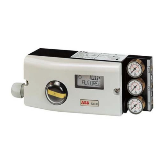
- Page 1 Operating Instructions Electro-Pneumatic Positioner TZIDC for 4...20 mA two wire technology 41/18 79 EN Software Revision 2.00...
- Page 2 More information, e.g. regarding configuration, operation and ordering details, is available on CD. © Copyright 2005 by ABB Automation Products GmbH Modifications reserved This document is subject to copyright. It is intended to help the user operate the equipment safely and efficiently.
-
Page 3: Table Of Contents
Table of contents Important information ....................... 5 1 Safety summary ......................6 General safety instructions ..................6 Device-specific safety instructions.................7 1.2.1 General ......................7 1.2.2 Pneumatic safety ..................7 1.2.3 Electrical safety ....................8 Explosion protection ....................9 Correct use........................9 Qualified personnel ....................10 2 Manufacturer's information .................. - Page 4 Electrical connection....................22 3.3.1 Safety instructions ..................22 3.3.2 General installation instructions ..............22 3.3.3 Overview....................... 23 3.3.4 Inserting the cable in the housing ..............24 3.3.5 Make the electrical connection ..............25 Commissioning.......................26 3.4.1 Commissioning procedure ................26 3.4.2 Operating modes, overview and selection............ 27 3.4.3 Parameter setting example................
-
Page 5: Important Information
Important information Symbols In order that you can make the best use of this document and to ensure safety during commis- sioning, operation and maintenance of the equipment, please note the following explanation of the symbols used: Symbol Signal Word Definitions DANGER DANGER indicates an imminently hazardous situation... -
Page 6: Safety Summary
Safety summary 1.1 General safety instructions This chapter provides important instructions for your safety. Thoroughly read and follow these instructions. Proper and safe operation of the TZIDC positioner requires: • proper transportation and storage • mounting, electrical and pneumatic installation and commissioning by qualified per- sonnel (see chapter 1.5, page 10) •... -
Page 7: Device-Specific Safety Instructions
1.2 Device-specific safety instructions 1.2.1 General • Any user-made changes or manipulations of the device are prohibited! Only the manufacturer or an expert for explosion protection are autho- rized to modify the device. • Before re-using a TZIDC positioner that has already been used in WARNING another installation place always reset the device to the factory setting. -
Page 8: Electrical Safety
1.2.3 Electrical safety • Observe the common VDE safety regulations and the accident preven- tion rules of the Employers Liability Insurance Association. • Observe the common standards and safety regulations for the installa- tion and operation of electrical systems. WARNING •... -
Page 9: Explosion Protection
NEMA 4X TYPE 4X INTRINSICALLY SAFE / SECURITE INTRINSIQUE Per Control Document No. 901064 ABB Automation Made in Germany Fig. 1 Type plates indicating the degree of explosion protection 1.4 Correct use The TZIDC positioner is an electro-pneumatic positioner with flameproof enclosure for pneumatic final control elements. -
Page 10: Qualified Personnel
1.5 Qualified personnel Only those persons familiar with the installation, commissioning, operation and mainte- nance of the TZIDC positioner or similar instruments who have the required qualification and have read and understood the operating instructions are authorized to work on the TZIDC positioner. -
Page 11: Installing And Commissioning
Installing and commissioning 3.1 Mechanical mounting 3.1.1 General The arrow (1) on the feedback shaft (and thus the lever) must travel within area marked with small arrows (2). Fig. 2 Operating range When mounting the positioner, ensure Sensor range for linear actuators that the transfer of +30°... -
Page 12: Operating Conditions At The Installation Site
3.1.2 Operating conditions at the installation site Before installing check to ensure that the specifications in terms of safety and control applicable to the TZIDC positioner will not be exceeded at the installation site of the actuator or final control element. WARNING Ambient temperature: -40 °C ... - Page 13 Follow the procedure (steps 1 - 5) below to attach the positioner to a linear actuator: 1. Mount the follower guide to the actuator • Fasten the follower guide (1) and the clamp plates (2) with screws (4) and spring washers (3) to the spindle of the actua- tor;...
- Page 14 3. Mount the lever and the angle bracket to the positioner Fig. 7 Mounting lever and angle bracket to TZIDC • Attach the lever (1) to the positioner’s feedback shaft (2) (can only be mounted in one position due to the flat on the side of the feedback shaft). •...
- Page 15 4.a Mount the positioner to a cast iron yoke • Fasten the angle bracket (1) with screw (2), plain washer (3) to the cast iron yoke (4). Positioner Fig. 8 Mounting to cast iron yoke 4.b Mount the positioner to a columnar yoke •...
- Page 16 5. Adjust the stroke increase decrease Fig. 10 Positioner linkage The scale on the lever indicates the relevant points for the various valve stroke ranges. You can adapt the valve stroke range to the operating range of the position sensor by shifting the bolt with follower pin in the oblong bore hole of the lever.
-
Page 17: Mounting The Positioner To Rotary Actuators
3.1.4 Mounting the positioner to rotary actuators The following mounting kit is available for mounting to a rotary actuator according to VDI/ VDE 3845: • Adapter (1.0) with spring (1.4) • Four screws, (1.1), four spring washers (1.2), and four plain washers (1.3) for fastening the bracket (2.0) to the positioner... - Page 18 Follow the procedure (steps 1 - 3) below to attach the positioner to a rotary actuator: 1. Mount the adapter to the positioner • Determine the mounting position (in parallel to the actuator or shifted by 90°). • Determine the direction of rotation of the actuator (clockwise or counterclockwise).
- Page 19 3. Attach the positioner to the actuator M5 screws Fig. 14 Attaching the positioner to the actuator After mounting, check whether the actuator’s operating range is in accor- dance with the positioner’s sensor range. Check the unit for proper mounting after having made the pneumatic and IMPORTANT electrical connection (see chapter "Commissioning"...
-
Page 20: Pneumatic Connection
3.2 Pneumatic connection 3.2.1 Safety instructions • Observe the accident prevention rules of the Employers Liability Insur- ance Association. • Observe the safety instructions for the pneumatic actuator used. The actuator's high actuating power may cause injuries ! WARNING • Take suitable precautions to ensure that even in case of malfunctions the positioner’s max. -
Page 21: Mounting The Splash Guard Cap
The connections have to be arranged, according to their marks, in the following way: Mark Connection piping Air supply, pressure 1.4...6 bar (20...90 psi) OUT1 Output pressure, to actuator OUT2 Output pressure, to actuator (second output, for double-acting actuators) 3.2.3 Mounting the splash guard cap Protection class IP 65 / NEMA 4 X is achieved only when the splash guard cap is in place. -
Page 22: Electrical Connection
3.3 Electrical connection 3.3.1 Safety instructions • Observe the common VDE safety regulations and the accident preven- tion rules of the Employers Liability Insurance Association • Observe the common standards and safety regulations for the installa- tion and operation of electrical systems. WARNING •... -
Page 23: Overview
3.3.3 Overview Two threaded bore holes 1/2 - 14 NPT or M20 x 1.5 are available on the left hand side as the cable entry into the case. One is equipped with a cable gland and in the other a pipe plug is mounted. -
Page 24: Inserting The Cable In The Housing
3.3.4 Inserting the cable in the housing In order to provide for sufficient EMI/RFI shielding of the positioner to meet the require- ments regarding electromagnetic compatibility (EMC), all electrical wires must be entered through a ferrite tube in the connection compartment. Proceed as described in the example below: 70 mm 6 mm... -
Page 25: Make The Electrical Connection
3.3.5 Make the electrical connection • Remove approximately 6 mm of the cable insulation. • To connect the signal lines, the shutdown module, the proximity switches or the microswitches insert the wire ends from the left into the appropriate screw terminals and hand-tighten the screws (access from above). -
Page 26: Commissioning
3.4 Commissioning 3.4.1 Commissioning procedure 1. Turn on the air supply to the positioner. 2. Turn on the electrical power supply to the positioner. Apply the 4...20 mA signal to the analog input (terminals +11/-12). 3. Check for proper mounting: Press and hold ;... -
Page 27: Operating Modes, Overview And Selection
3.4.2 Operating modes, overview and selection Procedure for mode selection from the operating level: • Press and hold MODE • Additionally briefly press as often as required. The selected mode is indicated. • Release MODE • The position is indicated as a percentage or rotation angle. Overview Mode Mode display... -
Page 28: Parameter Setting Example
3.4.3 Parameter setting example An overview of the parameter settings that can be edited via the front panel keypad is found in Appendix A. IMPORTANT "Changing zero position (of the LCD) from clockwise to counter-clockwise" Initial situation: the positioner is operating in mode 1.1. 1. -
Page 29: Functional Test / Maintenance
5. Change over to parameter 3.3 "EXIT" and save the new setting: Press and hold MODE Additionally 1 x briefly press ° is displayed. conf Release MODE Briefly press to select "NV_SAVE". Press and hold until the countdown has run down from 3 to 0. ENTER The positioner saves the new settings, automatically returns to the operating level and continues operation in the same mode that was active before the configuration level has... -
Page 30: Functional Test Of The Shutdown Module
3.5.1 Functional test of the shutdown module If the optional shutdown module is used, it must be subject to a functional test every two years at the latest to ensure full operational reliability in compliance with DIN V 19250. Otherwise, the AK4 approval will lapse. WARNING Proceed as described below: 1. -
Page 31: Technical Data
Technical data 4.1 Basic model Input Signal Two-wire technology Nominal range 4...20 mA Split range configuration betw. 20% and 100% of the nominal range Max. 25 mA / 30 V Min. 3.4 mA (without analog position feedback) 3.5 mA (with analog position feedback) Start from 3.8 mA Load voltage at 20 mA... - Page 32 Travel Angle of rotation Used range 25...120 ° (rotary actuators, optionally 270 °) 25...60 ° (linear actuators) Travel limit Min. and max. limits, freely configurable within 0...100 % of total travel (min. range > 20 %) Travel time prolongation Range of 0...200 seconds, separately for each direction Positioning time limit Range 0...200 seconds (monitoring parameter for control until the deviation reaches the tolerance band)
- Page 33 Influence of ambient temperature ≤ 0.5 % for every 10 °C change in temperature Influence of vibration ≤ ± 1 % up to 10 g and 80 Hz Seismic requirements Meets requirements of DIN/IEC 68-3-3 Class III for strong and strongest earthquakes Influence of mounting orientation No effect...
- Page 34 Safety Integrity Level EXIDA report No.: ABB 03/09-13 R003, Revision R1.0 The positioner TZIDC and the shutdown module for TZIDC meet the requirements regarding – functional safety in accordance with IEC 61508/IEC 61511-1 – explosion protection (depending on the model) –...
- Page 35 Explosion protection The values indicated here have been taken out of the respective approval cer- tificates. Always observe the specifications and supplements in the certificates (see WARNING chapter "Certificates" starting on page 38). FM J.I. 3005029 (3610, 3611) Intrinsically safe CL I, Div.
-
Page 36: Options
4.2 Options Module for analog position feedback Range 4 ... 20 mA (configurable split ranges) Two-wire circuitry, power supply 24 V DC (10...30 V DC) 48 V DC (20...48 V DC, no explosion protection) Action direct or reverse (configurable) Characteristic deviation < 1 % Note: Without a signal from the positioner (e.g. - Page 37 Digital position feedback with proximity switches 2 proximity switches for independent position signaling. Switching points adjustable between 0 and 100 % Current circuits to DIN 19234/NAMUR Supply voltage 5...11 V DC Signal current < 1.0 mA logical “0” Signal current > 2.0 mA logical “1”...
-
Page 38: Certificates
Certificates Electro-pneumatic positioner TZIDC 41/18-79 EN... - Page 39 41/18-79 EN Electro-pneumatic positioner TZIDC...
- Page 40 Electro-pneumatic positioner TZIDC 41/18-79 EN...
- Page 41 41/18-79 EN Electro-pneumatic positioner TZIDC...
- Page 42 Electro-pneumatic positioner TZIDC 41/18-79 EN...
- Page 43 41/18-79 EN Electro-pneumatic positioner TZIDC...
- Page 44 Electro-pneumatic positioner TZIDC 41/18-79 EN...
- Page 45 41/18-79 EN Electro-pneumatic positioner TZIDC...
- Page 46 Electro-pneumatic positioner TZIDC 41/18-79 EN...
- Page 47 41/18-79 EN Electro-pneumatic positioner TZIDC...
- Page 48 Electro-pneumatic positioner TZIDC 41/18-79 EN...
- Page 49 41/18-79 EN Electro-pneumatic positioner TZIDC...
- Page 50 Only the 7th. Supplement to the certificate TÜV 98 ATEX 1370 X is shown here, since the Supplements 2 to 6 do not contain information that is relevant for these operating instructions. Important Electro-pneumatic positioner TZIDC 41/18-79 EN...
- Page 51 41/18-79 EN Electro-pneumatic positioner TZIDC...
- Page 52 Electro-pneumatic positioner TZIDC 41/18-79 EN...
- Page 53 41/18-79 EN Electro-pneumatic positioner TZIDC...
- Page 54 Certificate No.: IECEx TUN 04.0015X Issue No.: Status: Current Date of Issue: 2004-07-29 Page Applicant: ABB Automation Products GmbH Schillerstraße 72 32425 Minden Germany Electrical Apparatus: Positioner type TZIDC-xxx Optional accessory: Type of Protection: Intrinsic safety; Type of protection "n"...
- Page 55 Conformity Certificate No.: IECEx 04.0015X Date of Issue: 2004-07-29 Issue No.: Page Manufacturer: ABB Automation Products GmbH Schillerstraße 72 32425 Minden Germany Manufacturing location(s): Automation Products GmbH Schillerstraße 72 32425 Minden Germany This certificate is issued as verification that a sample(s), representative of production, was assessed and tested and found to comply with the IEC Standard list below and that the manufacture’rs quality system, relating to the Ex products...
- Page 56 IECEx Certificate of Conformity Certificate No.: IECEx 04.0015X Date of Issue: 2004-07-29 Issue No.: Page Schedule EQUIPMENT: Equipment and systems covered by this certificate are as follows: The Positioner type TZIDC-xxx is used for the control resp. closed loop control of pneumatic driven valves. The Positioner type TZIDC resp.
- Page 57 pp y IECEx Certificate of Conformity Certificate No.: IECEx 04.0015X Date of Issue: 2004-07-29 Issue No.: Page Additional information: 41/18-79 EN Electro-pneumatic positioner TZIDC...
- Page 58 TÜV NORD CERT GmbH & Co. KG Am TÜV 1 D-30519 Hannover Annexe to IECEx TUN 04.0015X TÜV NORD CERT Page 1 of 3 Electrical data for type TZIDC resp. TZIDC-200 with marking Ex ib IIC T6 Signal circuit in type of protection “Intrinsic Safety” Ex ib IIC (terminals 11(+), 12(-)) only for the connection to a certified intrinsically safe circuit with the...
- Page 59 TÜV NORD CERT GmbH & Co. KG Am TÜV 1 D-30519 Hannover Annexe to IECEx TUN 04.0015X TÜV NORD CERT Page 2 of 3 Electrical data for type TZIDC-110, TZIDC-210, TZIDC-120 resp. TZIDC-220 with marking Ex ia IIC T6 Input circuit in type of protection “Intrinsic Safety”...
- Page 60 TÜV NORD CERT GmbH & Co. KG Am TÜV 1 D-30519 Hannover Annexe to IECEx TUN 04.0015X TÜV NORD CERT Page 3 of 3 Electrical data for type TZIDC, TZIDC-110 resp. TZIDC-120 with marking Ex nA II T6 Type TZIDC resp. TZIDC-200 Signal circuit U = 8.7 VDC;...
- Page 61 41/18-79 EN Electro-pneumatic positioner TZIDC...
- Page 62 Electro-pneumatic positioner TZIDC 41/18-79 EN...
- Page 63 41/18-79 EN Electro-pneumatic positioner TZIDC...
- Page 64 Electro-pneumatic positioner TZIDC 41/18-79 EN...
-
Page 65: Appendix A: Parameter Overview
41/18-79 EN Electro-pneumatic positioner TZIDC... - Page 66 Electro-pneumatic positioner TZIDC 41/18-79 EN...
- Page 67 41/18-79 EN Electro-pneumatic positioner TZIDC...
- Page 68 Electro-pneumatic positioner TZIDC 41/18-79 EN...
- Page 69 ABB. improvement and the right is reserved to modify the information contained herein without notice. ABB has Sales & Customer Support expertise in over 100 countries worldwide. Printed in the Fed. Rep. of Germany (04.05) www.abb.com ©...