Table of Contents
Advertisement
Quick Links
Download this manual
See also:
User Manual
A B B M E A S U R E M E N T & A N A LY T I C S | S TA RT U P G U I D E
XSeries
G5
Flow Computers and
Remote Controllers
G5
G5
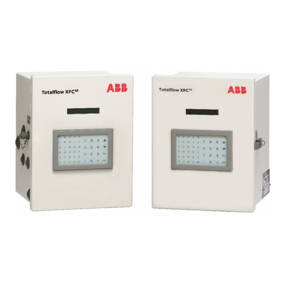
XFC
and XRC
Introduction
This startup guide provides basic installation and configuration procedures
for the XFC
G5
and XRC
performed by personnel knowledgeable of:
Flow computers and remote controllers
Local and national codes as they apply to hazardous areas
Communication and electrical wiring
Use this guide in conjunction with other drawings and documentation that
may accompany the product purchase order. Many sites have unique
installation requirements. In these cases, it is important to reference site-
specific documentation.
G5
. It is designed for typical installations only,
Scalable
measurement
control for
production
Measurement
made easy
Advertisement
Table of Contents

Related Manuals for ABB X Series G5


Summary of Contents for ABB X Series G5
- Page 1 A B B M E A S U R E M E N T & A N A LY T I C S | S TA RT U P G U I D E XSeries Flow Computers and Remote Controllers and XRC Scalable measurement...
-
Page 3: Table Of Contents
Contents Introduction ................1 Cyber security ................ 4 Additional information ............. 5 Safety .................. 6 Safety symbol conventions ............6 Potential safety hazards ............. 7 Compliance ................8 EU Directive 2012/19/EU – WEEE ..........8 FCC RF Compliance ..............8 Considerations before installation .......... - Page 4 4 Wire COMM ports ............... 30 XFC COMM pinouts ............30 XRC COMM pinouts ............34 5 Wire I/Os ................. 36 Analog input (AI) pinouts ........... 36 Digital input and output (DI/DO) pinouts ........ 38 6 Powering the device ............41 Super capacitor charging at boot time ........
- Page 5 LCD visual alarm and status codes ........72 Failure to start ............... 74 The screen has locked up ..........74 Remote communication failure ........... 75 Contact us: ................77...
-
Page 6: Cyber Security
ABB Inc. and affiliates are not liable for damages and/or losses related to such security breaches, unauthorized access, interference, intrusion, leakage and/or theft of data or information. -
Page 7: Additional Information
Additional information Additional free publications are available for download at www.abb.com/upstream. Related documents Document number 2106026 XSeries User Manual 2106079 XSeriesG5 Board Replacement Kit Guide 2101226 TFIO Module User Manual 2106123 Wi-Fi antenna kit installation guide User Drawings 2106114 Generic Pinout... -
Page 8: Safety
Safety Observe and follow warning signs on packaging in documentation and on the device. Installation and maintenance will only be conducted by personnel authorized to work on electrical installation. Installation and maintenance will be conducted in accordance with relevant national and local codes. -
Page 9: Potential Safety Hazards
IMPORTANT NOTE: This symbol indicates operator tips, particularly useful information, or important information about the product or its further uses. Potential safety hazards The XFC and XRC use voltages in the range of 9-12 Vdc plus some percent of tolerance. There are no hazardous voltages present in the device. However, some optional power sources may convert power from Vac to Vdc. -
Page 10: Compliance
Compliance EU Directive 2012/19/EU – WEEE Waste Electrical and Electronic Equipment (WEEE) marked using the crossed-out wheeled bin symbol shall not be mixed with general household waste. Correct disposal at a recycling facility will help save valuable resources and prevent potential negative effects on health and the environment. -
Page 11: Considerations Before Installation
Considerations before installation Versions of PCCU32 older than version 7.61 are not compatible. The installation of these meters, senior fitting, tap valves, or other peripheral equipment is outside the scope of this document. Assumptions The following is assumed: The XFC and XRC are designed to adapt to different site scenarios. This guide covers a standard single-tube configuration for the XFC flow computer for a common site scenario which requires: ... -
Page 12: Site Planning And Requirements
Site planning and requirements The XFC and XRC enclosures, power sources, wiring, and location must comply with the specifications described in this section. WARNING – Bodily injury. Select compliant equipment listed in this section or customer provided equipment. Carefully review the specifications. Failure to comply with these specifications may create unsafe conditions, resulting in bodily injury and equipment damage. -
Page 13: Wiring Requirements
For solar panel use, determine where and how to install the solar panel outdoors. For optimum charging, avoid placing the solar panel where it will be in shadow any part of the day. More information is available in section 3.2 Install the solar panel. This section describes the installation of the power equipment. -
Page 14: Basic Hardware Installation
Basic hardware installation The XFC and XRC can be pipe-mounted, wall-mounted, or direct-mounted to the meter run. IMPORTANT NOTE: Do not direct mount the larger enclosures (for XFC – 6713, 6714 and for XRC - 6790, 6890, 6895). Required tools and materials To perform installations and tests, the following tools and materials are required: Pipe mount installation:... -
Page 15: Unpack And Inspect
ABB main office number listed in Contact us:. IMPORTANT NOTE: Do not return equipment to ABB without prior written consent. Returns are subject to the terms and conditions specified by ABB. 2 1 0 60 01M NAA | XSER IE S G5 S TART UP G UI DE | 1 3... -
Page 16: Pipe Mount Installation
Pipe mount installation IMPORTANT NOTE: Select a mounting location that allows for easy access, is close to the tap valves, and complies with all local and national codes. Materials: One (1) enclosure mounting kit (includes instructions, brackets, U-bolts and fastening hardware) ... -
Page 17: Wall-Mount Installation
Level the mounting pipe: Level and center the pipe and saddle on the top of the meter run. Tighten the saddle-mounting U-bolt. Level the pipe so that the pipe is perpendicular to the meter run using the saddle leveling bolts (if available) on the mounting saddle. -
Page 18: Direct-Mount Installation
The following steps detail the procedures for wall-mounting the XFC or XRC by the meter run. Materials: One (1) enclosure mounting kit (includes instructions, brackets, U-bolts and fastening hardware) Four (4) wall fasteners (length and girth determined by technician based on wall thickness and materials) Wall-mount the XFC or the XRC: Inspect the installation location:... - Page 19 Two (2) stabilized manifold connectors (compatible with the manifold) Install the input lines and manifold: Install the manifold on the XIMV using the manufacturer's instructions. Locate the tap valves on the meter run orifice and the corresponding high and low inputs on the installed manifold. Measure, cut, and bend the tubing to ease installation of the fittings into the orifice tap valves and the manifold.
-
Page 20: Ground Equipment
Figure 2-2: XFC with XIMV attached to a 5-valve manifold 1 1 1 Legend - XFC with XIMV attached to a 5-valve manifold Instrument manifold, 5 valve XIMV Ground equipment Refer to the requirements of national and local electrical codes for the location. - Page 21 One (1) manifold (3-valve or 5-valve manifold determined by technician.) To install the input lines and manifold (XFC): Install the manifold on the XFC IMV using the manufacturer's supplied instructions. Locate the tap valves on the meter run orifice and the corresponding high and low inputs on the installed manifold.
-
Page 22: Install And Connect The Rtd For The Xfc
Figure 2-3: XFC with XIMV and 5-valve manifold Legend XFC with XIMV and 5 valve manifold High side equalizer valve XIMV Manifold vent valve Enclosure Low side equalizer valve Connect the pressure device to the test port. Apply pressure to the port based on the transducer range (100% of range). - Page 23 — Wiring the RTD leads to the XFC electronic board WARNING: Bodily injury. Install electrical wiring according to requirements for the area classification. Refer to the certification drawing indicated on the device’s name tag, and national and local codes. Materials: ...
- Page 24 Figure 2-5: RTD probe connector Legend: RTD Probe Connector 1 SHLD (Drain wire= Green wire) Cable 2 OUT (White wire) Retaining ring 3 (+) (White wire) 10 RTD probe 4 (-) (Black wire) 11 Spring 5 IN (Black wire) 12 Probe connector 6 Cable gland 13 Nylon sealing ring 7 Cord sealing nut...
-
Page 25: Wire The Rtd To The Xfc
Wire the RTD sensor cable to the J7 terminal block using the wires identified in Figure 2-5: RTD probe connector, RTD probe connector, and the pinouts identified in the following. Wire the RTD to the XFC WARNING: Bodily injury. Wire peripheral devices to the flow computer electronic board before power is applied. -
Page 26: Install Antenna (For Wireless Functionality)
Install antenna (for wireless functionality) IMPORTANT NOTE: The XSeries Wi-Fi Kit is required for antenna installation. See Additional information. ® ® Install the antenna to support onboard Bluetooth and Wi-Fi wireless interfaces. Use the onboard connector ANT-1 (J42) to connect the antenna. Use the cap to isolate the unused antenna connector (ANT-2). -
Page 27: Install Battery And Charger
Install battery and charger The XFC and XRC support either of two power modes. Battery mode: The primary power source to the device is a 12 volt sealed lead acid battery with nominal 12 V solar panel charger. External power mode: The primary power source to the device is an external power supply (14.5 to 15.5 Vdc maximum). -
Page 28: Install The Solar Panel
If the measured voltage is out of specification, contact ABB for a replacement panel. 2 6 | XSE RI ES G5 STA RT UP GUI DE | 21 0 60 0 1MNAA... - Page 29 Install the mounting bracket on the solar panel using the provided hardware. If installation requires a mounting pipe extension: Attach the pipe coupling to the top end of the flow computer mounting pipe. Securely tighten the pipe coupling. Attach the extension pipe to the pipe coupling. Attach the solar panel mounting bracket to the top end of the mounting pipe with the U-bolts and associated mounting hardware.
- Page 30 WARNING – Bodily injury. Install the electrical wiring according to requirements for the area classification. Refer to the certification drawing indicated on the device’s name tag, and national and local electrical codes. Secure the solar panel cable to the pipe: Do not wrap the cable around the mounting pipe.
- Page 31 Figure 3-2: CHRG terminal block on the XFC NOTICE – Equipment damage. Do not over-tighten the terminal connector screws as this may damage the wires. NOTICE – Equipment damage. Do not connect the solar panel to the electronic board before battery connection. Damage to the board will void any warranty.
-
Page 32: Wire Comm Ports
Wire COMM ports Wire the XFC or XRC COMM ports to communicate with and power external devices. Wiring for communication depends on the type of serial interface required by the device. Wiring for power is required if there is no external supply powering the external device. - Page 33 Figure 4-1: XFC R-232 COMM1 IMPORTANT NOTE: Typically only TXD, RXD and GND may be required to communicate with a third party RS-232 device. The figure above illustrates all lines associated with COMM 1 or COMM2 RS-232 module. Figure 4-2: XFC R-232 COMM2 2 1 0 60 01M NAA | XSER IE S G5 S TART UP G UI DE | 3 1...
- Page 34 RS-485 supports multiple devices per port. For additional wiring options, search additional user drawings at www.abb.com/upstream. Figure 4-3: XFC-485 COMM1 3 2 | XSE RI ES G5 STA RT UP GUI DE | 21 0 60 0 1MNAA...
- Page 35 IMPORTANT NOTE: Typically only BUS+, BUS- and GND may be required to communicate with a third party RS-485 device. The figure above illustrates all lines associated with COMM 1 or COMM2 RS-485 module. Figure 4-4: XFC R-485 COMM2 Table 4-3: XFC RS-485 COMM1 and COMM 2 RS-485 COMM 1 RS-485 COMM 2 VBATT...
-
Page 36: Xrc Comm Pinouts
IMPORTANT NOTE: Figure 4-6 (RS-485 COMM1) shows connection lines to a single device. RS-485 supports multiple devices per port. For additional wiring options search additional user drawings at www.abb.com/upstream. 3 4 | XSE RI ES G5 STA RT UP GUI DE | 21 0 60 0 1MNAA... - Page 37 Figure 4-6: XRC RS-485 COMM 1 Table 4-4: XRC COMM 1 and COMM 2 pinouts RS-232 COMM 1 and 2 RS-485 COMM 1 and 2 VBATT VBATT SW VBATT SW VBATT OPER OPER RRTS BUS- BUS- BUS+ BUS+ 2 1 0 60 01M NAA | X SER IE S G 5 S TART UP G UI DE | 3 5...
-
Page 38: Wire I/Os
Wire I/Os Wire the XFC or XRC I/O ports to monitor or control external devices. IMPORTANT NOTE: Refer to the XFC or XRC user drawings for I/O wiring details for specific external devices. See Additional information. NOTICE – Equipment damage. An external device can be powered from VBAT or SW VBAT pins on the COMM terminals. - Page 39 Table 5-1: XFC AI Pinouts Input Description AI-1 (+) Input signal (-) Input ground AI-2 (+) Input signal (-) Input ground The XRC has five onboard analog inputs. Determine the AI and refer to the pinout table for wiring. Figure 5-2 shows the XRC analog input terminals and the input mode selector jumpers.
-
Page 40: Digital Input And Output (Di/Do) Pinouts
Digital input and output (DI/DO) pinouts IMPORTANT NOTE: Digital inputs may be used as Pulse Inputs. The XFC has 2 onboard digital outputs and 2 onboard digital inputs. Figure shows the Digital I/O terminals on the XFC and the input mode switches. - Page 41 The XRC has four onboard digital outputs and four onboard digital inputs. Figure 5-4 shows the Digital I/O terminals on the XRC, the input mode switches, and the debounce jumpers. The input mode switches support standard pulse inputs (STD) or pulse inputs from Coriolis (IEC). Remember to set the switch to the correct position based on the pulse input signal expected (Use S3 for DI/PI 1, S4 for DI/PI 2, S7 for DI/PI 3 and S8 for DI/PI By default the debounce jumpers are set to enable debounce on the DI/PI.
- Page 42 Table 5-4: XRC DI/PI/DO Pinouts Description Description J8-A J8-B Signal Signal Signal Signal DI1/PI1 Signal DI3/PI3 Signal DI2/PI2 Signal DI4/PI4 Signal 4 0 | XSE RI ES G5 STA RT UP GUI DE | 21 0 60 0 1MNAA...
-
Page 43: Powering The Device
Powering the device Apply power to the XRC or XFC by making the correct connections for the power mode chosen. The XFC and XRC support two power modes: Battery mode: The primary power source is a 12 volt battery with a charger. -
Page 44: Power With Battery And Charger
Figure 6-1: XFC Display startup messages (part numbers are examples) IMPORTANT NOTE: If the LCD fails to display the startup sequence, see section Troubleshooting. Power with battery and charger Operating in battery power mode requires a 12 volt sealed lead acid (SLA) battery and a charger to recharge the battery. -
Page 45: Connect The Charger
Connect the battery to the BATT terminals on the XFC (J1 as shown below) or XRC (J16). Observe the polarity (+ and -). Figure 6-2: XFC BATT connector Confirm that the battery is supplying power to the XFC or XRC by observing the power-on sequence information scrolling on the LCD (see details in Section 6.1 Super capacitor charging at boot... -
Page 46: Power With External Power Supply
Figure 6-4: XFC charger connection Power with external power supply An external power supply can power the XFC and XRC. The XFC and XRC are 12 Vdc nominal powered devices. The voltage range from an external supply must be 9 Vdc to 15.5 Vdc. NOTICE –... -
Page 47: Enable Real Time Clock Backup
Enable real time clock backup Figure 6-6: Battery and switch Legend – S1 Security switch Battery Security switch The lithium battery maintains operation of the real time clock. The lithium battery backup jumper (J13) is located near the lithium battery slot. The two settings are: Enable –... -
Page 48: Local Communication With The Device
Local communication with the device Initial communication with the XFC or XRC can be established with a direct connection to the RS-232 (MMI) or USB ports. Note that communication on the USB port is faster. Use the appropriate cable for each port. For details on cable specifications, adapters or drivers, refer to the user manuals. -
Page 49: Establish Connection With The Xfc Or Xrc
Figure 7-1: System Setup Click Close. Establish connection with the XFC or XRC Connect to the device entry mode: On the PCCU32 tool bar, click Entry to connect to the device. Figure 7-2: PCCU32 Tool bar and Entry 2 1 0 60 01M NAA | XSER IE S G5 S TART UP G UI DE | 4 7... - Page 50 Table 7-1: PCCU 32 Elements Number Element name Tool bar Entry button If the XFC or XRC clock date and time is different from the laptop's, a message box displays with the option to synchronize the date and time. Figure 7-3: PCCU32 Date/Time synchronization warning IMPORTANT NOTE: Click Help for more information.
-
Page 51: Change To Expert View
Figure 7-4: PCCU32 XFC G5 Entry Screen Change to Expert view Use PCCU Expert view to complete initial and advanced configuration. Change the view while connected to the XFC or XRC: While connected to the XFC or XRC (Entry mode), on the top PCCU32 menu bar, select View. -
Page 52: Configure The Basic Parameters
Configure the basic parameters Station parameters Configure basic station parameters: At the PCCU32 Entry screen, click the station ID (TOTALFLOW) at the top of the navigation tree. The Station Setup tab displays. Figure 8-1: Station Setup Set up the basic station configuration parameters identified in the following table. -
Page 53: Change The Default Time And Date Format
Table 8-1: Required Station Setup Entry Format Description Station 10 digit The station identifier code is unique. If alphanumeric running a multiple tube station, the station ID is the same for all tubes on the device. If left blank on a single tube device, the station ID will be the same as the device ID. -
Page 54: Initial Measurement Application Setup
Initial measurement application setup The XFC or XRC shipped with standard configuration and the gas orifice measurement application configured by default. This procedure describes the setup of that flow measurement application (single tube). To set up additional tubes, or for different measurement application types, refer to the user manuals listed in Additional information, the application... - Page 55 In the Calculation Type field, select the calculation standard for this tube. In the Fpv Method field, select the compressibility method for this tube. Figure 9-2: Flow measurement > setup > General tab Click Send. Select the Constants tab. Figure 9-3: Constants Tab 2 1 0 60 01M NAA | XSER IE S G5 S TART UP G UI DE | 5 3...
- Page 56 Verify or update the following: For Barometric pressure, type the value, subtracted from the absolute pressure readings when calibrating in gauge pressure. IMPORTANT NOTE: Barometric pressure is area dependent. Use the correct barometric pressure for the area or the contracted value.
-
Page 57: Configure Communications
Configure communications Configure and enable communication interfaces when needed: Before configuration, wire communication or peripheral equipment to the serial communication (COMM) terminals. See section 4: Wire COMM ports. For remote or local network communication, note that enabling Ethernet, Wi-Fi or Bluetooth will cause additional power consumption. Configure COMM1 The XFC and XRC have standard configurations with COMM1 configured for remote communications with a host. - Page 58 Figure 10-2: TF Remote - COM 1 On the Protocol menu, select the appropriate protocol if not using the default Totalflow Remote. Under Serial Port Settings, on the Interface menu, select the communication interface (RS-232, RS-485, or RS-232 Modem). Verify, and change if necessary, the remaining serial port settings and timeouts and delays.
- Page 59 For RS-485 communication, position the termination jumpers according to the following table: Table 10-2: RS-485 Termination on COMM1 Position of the device on the Bus XFC J11 XRC J7 Last or only unit Intermediate unit Click Send changes to device after all values have been set. 10.
-
Page 60: Configure Comm2
IMPORTANT NOTE: This procedure assumes that the default generic serial communication configuration is used. Additional configuration options, which optimize support for specific ABB products, are also available (for example, the XMV Interface application). For details on these options, click Help from the Communications Setup tab screen and configure the port as required by the external device. -
Page 61: Configure For Network Communication
IMPORTANT NOTE: If the protocol selected is any of the MODBUS® options in the list, select the appropriate register format (in the Modbus Format Settings fields). Verify or configure the serial port settings to match the settings of the external device. For RS-485 communication, position the onboard termination jumpers according to the following table: Table 10-3: RS-485 Termination on COMM2... -
Page 62: Enable And Configure Ethernet
Use the Network ID to identify the XFC or XRC for connections on Wi- Fi or Bluetooth. Figure 10-5: Network tab – Configure network ID Enable and configure Ethernet To connect the XFC or XRC to a network, enable the Ethernet interface (Network Adapter) and configure the device with a valid public IP address. -
Page 63: Enable Wi-Fi
Figure 10-6: Enable and configure Ethernet communication Click Send. A message displays to confirm the change. Click Yes to confirm. Click Re-read to refresh the screen and verify that the Ethernet Status displays Ready. Verify that the saved IP configuration is correct. If DHCP is enabled, the IP parameters automatically configure. - Page 64 enabling Wi-Fi, the factory default parameters offer the highest security and number of users. Change the default configuration to meet field security requirements. This procedure enables Wi-Fi and changes the default security passcode (recommended). For non-default configuration or additional details click Help from the Wi-Fi tab screen.
- Page 65 security passcode and keep it safe as it will be required to establish a connection from Wi-Fi clients. IMPORTANT NOTE: If planning to leave the XFC or XRC with the security switch on, make sure to test the passcode before leaving the field.
-
Page 66: Enable Bluetooth
When prompted, provide the security passcode and click OK. View the list of wireless networks again and verify that the client shows Connected. A connected status indicates that the Wi-Fi client has been authenticated and automatically assigned an IP address. 12. - Page 67 Figure 10-9: Enable Bluetooth Select the Communication Setup tab. The Bluetooth port displays as unused in the port list. Figure 10-10: Communication Setup for Bluetooth 10. Select Bluetooth (Unused). 11. Select Add New Device/Application. See the figure below. 2 1 0 60 01M NAA | XSER IE S G5 S TART UP G UI DE | 6 5...
- Page 68 Figure 10-11: Add/Assign Bluetooth application to Bluetooth interface 12. Select Bluetooth. 13. Click OK. 14. Click Send Changes to device. 15. On the Communication Setup tab, verify that the port list and the description both display Bluetooth. See the figure below. Figure 10-12: Verify Bluetooth application assignment 16.
- Page 69 Verify that the XFC or XRC Network ID displays in the list of detected devices (see Figure 10-13: PCCU Connection Setup for Bluetooth). If unable to detect the XFC or XRC device, see section Troubleshooting. Select the device on the list and highlight. Click Select.
-
Page 70: Configure Basic Security (Recommended)
Configure basic security (recommended) This procedure configures activates secured access to the XFC or XRC by changing the default (OFF) position of the onboard security switch and configuring the bi-level security codes. IMPORTANT NOTE: After this procedure is completed, connection to the XFC or XRC is restricted to users with the correct security codes. - Page 71 Figure 11-2: Station Setup tab – Security switch status Type a four digit security code for Security Code Level 1 (read only access). Type a four digit security code for Security Code Level 2 (read and write access). IMPORTANT NOTE: Record the security codes. Once saved, they are not visible on the Station Setup tab.
-
Page 72: Commission The Device
Commission the device Commissioning the XFC or XRC is a two-part process: Validate the device measurement Place the device in service. Validate the device measurement The XFC and XRC are calibrated at the factory before shipping. However, shipping and installation may introduce errors into the measurement results. -
Page 73: Optional Volume Reset (Recommended)
Figure 12-1: Flow computer with 5 valve manifold Legend XFC with XIMV and 5 valve manifold High side equalizer valve Low side tap valve High side tap valve Manifold vent valve Low side equalizer valve XIMV Verify the equalization valves (items 1 and 3) are open. Verify the manifold vent valve (item 5) is closed. -
Page 74: Troubleshooting
Troubleshooting This section discusses a few potential issues during the initial startup of the flow computer. IMPORTANT NOTE: For complete troubleshooting instructions, refer to the Troubleshooting section of the user manual, see Additional information. LCD visual alarm and status codes The LCD displays alarm conditions and status codes in the Annunciator area, see Figure 13-1: XSeriesG5... - Page 75 Table 13-1: XSeries status and alarm codes Indicator Description System Low Lithium Battery Alarm: When LL (low lithium) is displayed, the lithium battery voltage is below 2.5 Vdc. A new lithium battery measures approximately 3.6 Vdc. Low Charger: When LC (low charger) is displayed, the XSeries battery charging voltage is (+) 0.4 Vdc, or is less than or equal to the battery voltage.
-
Page 76: Failure To Start
Indicator Description readings exceed the maximum counts or are less than the minimum counts Display Applications A number represents the Display Group number currently displayed. The displayed item’s value is above the Data High Limit value ↑ on the display Item Setup screen. The displayed item’s value is below the Data Low Limit value ↓... -
Page 77: Remote Communication Failure
If the display does not begin cycling correctly or locks up on one of the startup screens, contact technical support for additional instructions. IMPORTANT NOTE: To reach technical support, call the ABB Totalflow main office, listed under Contact us: and select technical support from the menu options. - Page 78 Communication troubleshooting section of the user manual. See Additional information. For troubleshooting other communication equipment, including modems, cellular equipment, or telephone line, contact the ABB Totalflow main office, listed under Contact us:, and select technical support from the menu options.
-
Page 79: Contact Us
We reserve all rights in this document and in the subject matter and illustrations contained therein. Any reproduction, disclosure to third parties or utilization of its contents - in whole or in parts – is forbidden without prior written consent of ABB. Windows® is a registered trademark of Microsoft.