Table of Contents
Advertisement
Quick Links
Converter Module
Thank you for purchasing the programmable controller.
Prior to use, please read this and relevant manuals thoroughly to
fully understand the product.
© 2011 MITSUBISHI ELECTRIC CORPORATION
Analog-Digital
AJ65SBT2B-64AD
MODEL
MODEL
CODE
IB(NA)-0800466-D(1806)MEE
User's Manual
(Hardware)
AJ65SBT2B64AD-U-HW
13J256
Advertisement
Table of Contents

Related Manuals for Mitsubishi Electric AJ65SBT2B-64AD


Summary of Contents for Mitsubishi Electric AJ65SBT2B-64AD
- Page 1 Analog-Digital Converter Module User’s Manual (Hardware) AJ65SBT2B-64AD Thank you for purchasing the programmable controller. Prior to use, please read this and relevant manuals thoroughly to fully understand the product. MODEL AJ65SBT2B64AD-U-HW MODEL 13J256 CODE IB(NA)-0800466-D(1806)MEE © 2011 MITSUBISHI ELECTRIC CORPORATION...
-
Page 2: Safety Precautions
SAFETY PRECAUTIONS (Read these precautions before using this product.) Before using this product, please read this manual and the relevant manuals carefully and pay full attention to safety to handle the product correctly. The precautions given in this manual are concerned with this product only. For the safety precautions of the programmable controller system, refer to the user’s manual for the CPU module used. - Page 3 [Design Precautions] CAUTION ● Do not install the control lines or communication cables together with the main circuit lines or power cables. Keep a distance of 100mm or more between them. Failure to do so may result in malfunction due to noise. [Installation Precautions] CAUTION ●...
- Page 4 [Wiring Precautions] CAUTION ● Check the rated voltage and terminal layout before wiring to the module, and connect the cables correctly. Applying a voltage or inputting a current that exceeds the absolute maximum input of the module, connecting a power supply with a different voltage rating, or wiring the cables incorrectly may cause a fire or failure.
- Page 5 [Starting and Maintenance Precautions] CAUTION ● Do not disassemble or modify the module. Doing so may cause failure, malfunction, injury, or a fire. ● Use any radio communication device such as a cellular phone or PHS (Personal Handy-phone System) more than 25cm away in all directions from the module.
- Page 6 PRÉCAUTIONS DE SÉCURITÉ (Lire ces précautions avant toute utilisation du produit.) Avant d'utiliser ce produit, lire attentivement ce manuel ainsi que les manuels auxquels il renvoie, et toujours considérer la sécurité comme de la plus haute importance en manipulant le produit correctement. Les précautions à...
- Page 7 [Précautions lors de la conception] ATTENTION ● Ne pas entremêler les lignes de commandes ou câbles de communication avec les lignes des circuits principaux ou les câbles d'alimentation. Les installer en maintenant entre eux une distance minimum de 100 mm. Faute de quoi, il y a risque de dysfonctionnement par un bruit.
- Page 8 [Pécautions de câblage] ATTENTION ● Mettre à la masse la borne FG pour le conducteur de mise à la terre protecteur dédié au contrôleur programmable. Faute de quoi, il y a risque d'électrocution et de dysfonctionnement. ● Serrer les vis des bornes inutilisées dans les limites du couple de serrage prescrit (0,42 à...
- Page 9 [Pécautions de câblage] ATTENTION ● Vérifier la tension nominale et l'affectation des bornes avant le câblage du module et raccorder les câbles correctement. Toute exposition d'une entrée du module à une tension ou à un courant dépassant la valeur maximum admissible, tout raccordement d'une alimentation d'une tension nominale incorrecte ou toute erreur de câblage peuvent être à...
- Page 10 [Précautions de démarrage et de maintenance] ATTENTION ● Ne pas démonter ni modifier le module. Cela pourrait entraîner des pannes ou dysfonctionnements et être à l'origine de blessures ou de départs de feu. ● Utiliser les appareils de communication radio tels que les PHS (systèmes de téléphone portable) à...
- Page 11 CONDITIONS OF USE FOR THE PRODUCT (1) Mitsubishi programmable controller ("the PRODUCT") shall be used in conditions; i) where any problem, fault or failure occurring in the PRODUCT, if any, shall not lead to any major or serious accident; and ii) where the backup and fail-safe function are systematically or automatically provided outside of the PRODUCT for the case of any problem, fault or failure occurring in the PRODUCT.
- Page 12 Notwithstanding the above, restrictions Mitsubishi may in its sole discretion, authorize use of the PRODUCT in one or more of the Prohibited Applications, provided that the usage of the PRODUCT is limited only for the specific applications agreed to by Mitsubishi and provided further that no special quality assurance or fail-safe, redundant or other safety features which exceed the general specifications of the PRODUCTs are required.
- Page 13 This manual confers no industrial property rights or any rights of any other kind, nor does it confer any patent licenses. Mitsubishi Electric Corporation cannot be held responsible for any problems involving industrial property rights which may occur as a result of using the contents noted in this manual.
-
Page 14: Table Of Contents
CONTENTS 1. OVERVIEW ....................1 2. SPECIFICATIONS..................2 2.1 General Specifications ................2 2.2 Performance Specifications..............4 3. PART NAMES ....................6 3.1 Part Names ....................6 4. LOADING AND INSTALLATION ..............10 4.1 Handling Precautions ................10 5. WIRING OF DATA LINK CABLES..............11 5.1 Wiring Precautions ................. - Page 15 The manual related to this product is shown below. Please place an order as needed. RELEVANT MANUAL Manual Number Manual name (Model code) Analog-Digital Converter Module Type AJ65SBT2B-64AD User's SH-080979ENG-A Manual (13JZ57) COMPLIANCE WITH EMC AND LOW VOLTAGE DIRECTIVES (1) Method of ensuring compliance...
-
Page 16: Overview
1. OVERVIEW This user's manual explains the specifications, part names, and wiring of the AJ65SBT2B-64AD analog-digital converter module (hereafter abbreviated as AJ65SBT2B-64AD) used as a remote device station of a CC-Link system. Before use, check that the following product is included. -
Page 17: Specifications
2. SPECIFICATIONS 2.1 General Specifications The general specifications of the AJ65SBT2B-64AD are shown in the following table. Table 2.1 General specifications Item Specifications Operating ambient temperature 0 to 55 Température 0 à 55 ambiante de fonctionnement Storage ambient -20 to 75... - Page 18 0m. Doing so may cause malfunction. When using the programmable controller under pressure, please consult your local Mitsubishi Electric representative. This indicates the section of the power supply to which the equipment is assumed to be connected between the public electrical power distribution network and the machinery within premises.
-
Page 19: Performance Specifications
2.2 Performance Specifications The performance specifications of the AJ65SBT2B-64AD are shown in the following table. Item AJ65SBT2B-64AD Voltage -10 to 10VDC (Input resistance: 1M ) Analog input Current 0 to 20mADC (Input resistance: 250 ) Digital output 16-bit singed binary (-16384 to 16383) - Page 20 Item AJ65SBT2B-64AD Built-in terminating resistor Provided (110 ) Communication part, module 7-point two-piece terminal block power supply M3 5.2 screw (tightening torque range: 0.59 to 0.88N•m) part Applicable solderless terminal: 2 or less Partie External Plaque à bornes 7-points deux pièces...
-
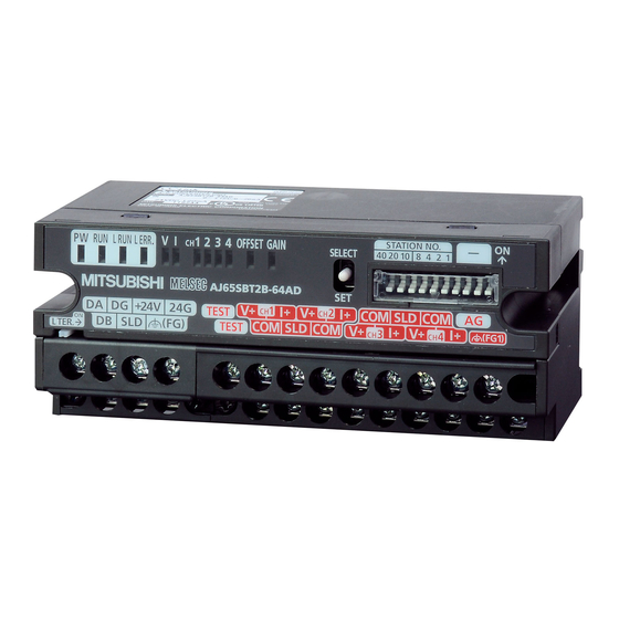
Page 21: Part Names
3. PART NAMES 3.1 Part Names This section explains the part names of the AJ65SBT2B-64AD. TEST +24V TEST Figure 3.1 Appearance of the AJ65SBT2B-64AD... - Page 22 Table 3.1 Part names Name Description On: Power supply on Off: Power supply off Normal operation Flashing: 0.1s Any of the following occurs: intervals: An analog value outside the analog input range is input. An user range read error Normal occurs.
- Page 23 Table 3.1 Part names Name Description With the STATION NO. "10", "20", and "40" switches, the tens place of the station number is set. With the STATION NO. "1", "2", "4", and "8" switches, the ones place of the station number is set. These switches are all set to off at default.
- Page 24 DIN rail hook A hook to mount the module to a DIN rail This switch is turned on to enable the built-in terminating resistor. L TER. (Line This switch is used when the AJ65SBT2B-64AD is connected at the end Termination) of the network.
-
Page 25: Loading And Installation
TH35-7.5Fe TH35-7.5Al (b) Installation screw intervals Tighten the screws at intervals of 200mm or less. (3) When mounting the AJ65SBT2B-64AD to a DIN rail, push in the DIN rail hook until it clicks. DIN rail DIN rail hook Figure 4.1 Mounting a module to a DIN rail (4) For names, specifications, and manufacturers of applicable cables, refer to the user’s manual for the master module used. -
Page 26: Wiring Of Data Link Cables
AJ65SBT2B-64AD. Les borniers de communication sont différents pour les AJ65SBT-64AD et pour les AJ65SBT2B-64AD. Si on remplace le AJ65SBT-62DA par un AJ65SBT-64DA, il faut recâbler le système en utilisant des borniers de communication prévus pour le AJ65SBT-64DA. -
Page 27: Connecting Terminating Resistors
5.3 Connecting Terminating Resistors The AJ65SBT2B-64AD has a built-in terminating resistor of 110 . There is no need to connect a terminating resistor externally. When using the AJ65SBT2B-64AD at the network termination, turn on the L TER. Switch. The factory default setting of the switch is off. -
Page 28: Wiring
Precautions for external wiring are as follows: (1) Use separate cables for the AC control circuit and the external input signals of the AJ65SBT2B-64AD to avoid the influence of the AC side surges or induction. (2) Do not install cables together with the main circuit lines, high voltage lines, or power cables for equipment other than the programmable controller. -
Page 29: Wiring With External Devices
Figure 6.1 Wiring with external devices Use shielded twisted pair cables. Input resistors of the AJ65SBT2B-64AD For the current input, wire between the V+ and I+ terminals. If there is noise or ripples in the external wiring, connect a 0.1 to 0.47 F capacitor (25V or higher voltage-resistant product) between the V+ and COM terminals. - Page 30 English French For voltage input Pour entrée de tension For current input Pour entrée de courant Signal source 0 to ±10VDC Source de signal 0 à 10V cc Signal source 0 to ±20mA Source de signal 0 à 20mA Shield Blindage Wiring with external devices Câblage à...
-
Page 31: External Dimensions
7. EXTERNAL DIMENSIONS The following diagrams show the external dimensions of the AJ65SBT2B-64AD. 109.5 Mounting hole (2-4.5 5.1, M4 screw) DIN rail center Unit : mm... - Page 32 20 Waterford Office Park, 189 Witkoppen Road, Avenida Adelino Cardana, 293, 21 andar, Fourways, South Africa Bethaville, Barueri SP, Brazil Tel : +27-11-658-8100 Tel : +55-11-4689-3000 Germany MITSUBISHI ELECTRIC EUROPE B.V. German China MITSUBISHI ELECTRIC AUTOMATION (CHINA) Branch LTD. Mitsubishi-Electric-Platz 1, 40882 Ratingen, No.1386 Hongqiao Road, Mitsubishi Electric...