
Related Manuals for Mitsubishi Electric Procon A1M


Summary of Contents for Mitsubishi Electric Procon A1M
- Page 1 Procon FOR INSTALLERS INSTALLATION MANUAL Version 1.1.1 For safe and correct use, please read this installation manual thoroughly before installing the PROCON A1M. MITSUBISHI ELECTRIC...
-
Page 3: Preface
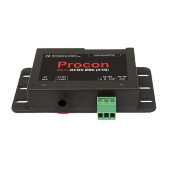
Do not expose to rain or moisture. Shielded Signal Cables: Use only shielded cables for connecting peripherals to any Procon A1M device to reduce the possibility of interference with radio communications services. Using shielded cables ensures that you maintain the appropriate EMC classification for the intended environment. - Page 4 [Fig. 1] RS-485 connector CN105/CN92 connection lead Page 1 of 12...
- Page 5 [Fig. 2] Page 2 of 12...
-
Page 6: Table Of Contents
RS-485 termination ............................6 Installation ................................. 7 4.1. Physical connection between the Procon A1M and M-, S-, and P-Series indoor units ........7 4.2. Power supply ..............................7 4.3. Modbus connections ............................7 ... -
Page 7: Safety Precautions
1. Safety precautions Before installing the unit, make sure you read all the “Safety precautions” The “Safety precautions” provide very important points regarding safety. Make sure you follow them Symbols used in the text Warning: Describes precautions that should be observed to prevent danger of injury or death to the user. Caution: Describes precautions that should be observed to prevent damage to the unit. -
Page 8: Overview
2. Overview The Procon A1M Protocol Converter is used for remote monitoring and control of M-, S- and P-series split air conditioning systems. It acts as a gateway between the split system and external third party equipment. The A1M continuously reads data from the indoor unit and changes configuration when necessary. Because the reading is continuous the A1M always stores up-to-date data. -
Page 9: Settings
3. Settings There is a bank of 8 DIP switches on the Procon A1M PCB labelled as ‘CONFIGURATION’. These switches are used to configure the Modbus Slave ID and the RS-485 baud rate. 3.1. Modbus Slave ID Any Modbus Slave ID in the range 1 – 31 can be chosen using switches 1 – 5. The address is set in binary, where the... -
Page 10: Installation
4.1. Physical connection between the Procon A1M and M-, S-, and P-Series indoor units The Procon A1M has a 1 metre flying lead to connect directly into the CN105/CN92 connector on the indoor unit controller PCB. As an example, Figure 2 shows this connection on a Mr Slim indoor unit. -
Page 11: Status Leds
Please note: if one or both of the LEDs are permanently on, this indicates that the Procon A1M is powered successfully, but no communication traffic is present. In this case please check the Slave ID settings, and ensure the CN105/CN92 connector is seated correctly. -
Page 12: Modbus Connection
6. Modbus connection 6.1. Modbus background Modbus is a master-slave protocol, which means there are two types of Modbus device, Modbus Masters and Modbus Slaves. Slave devices simply wait until they receive a command from a Master, act upon that command and send a reply to the Master. -
Page 13: Modbus Tables
7. Modbus tables 7.1. Modbus registers Modbus Slave devices store data in registers. There are four register types and each type has its own register bank. The register types are summarised below: Register Name Register Type Description Read only register used for holding status information which holds Discrete Input Digital Input a value of 0 or 1. -
Page 14: Holding Registers
7.5. Holding registers Holding Registers are read using function code 03 and written to using either function code 06 or 16. Function code 06 is used when writing to a single holding register, function code 16 is used for writing to multiple holding registers in the same command. - Page 15 Page 12 of 12...
- Page 16 Please be sure to put the contact address/telephone number on this manual before handing it to the customer. MITSUBISHI ELECTRIC UK MITSUBISHI ELECTRIC UK, TRAVELLERS LANE, HATFIELD, HERTFORDSHIRE, AL10 8XB...