Table of Contents
Advertisement
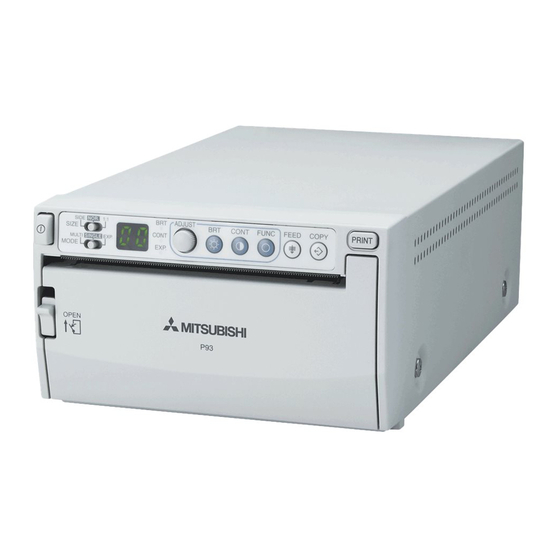
VIDEO COPY PROCESSOR
MODEL
P93W
P93E
OPERATION MANUAL
BRT
ADJUST
SIDE
NOR
1:1
BRT
CONT
SIZE
CONT
MULTI
SINGLE EXP.
MODE
EXP.
OPEN
THIS OPERATION MANUAL IS IMPORTANT
TO YOU.
PLEASE READ IT BEFORE USING YOUR
VIDEO COPY PROCESSOR.
VIDEO COPY
This video copy processor complies with the requirements of the EC Directive 89/336/
EEC, 73/23/EEC, 93/42/EEC and 93/68/EEC.
The electro-magnetic susceptibility has been chosen at a level that gains proper
operation in residential areas, on business and light industrial premises and on small-
scale enterprises, inside as well as outside of the buildings. All places of operation are
characterised by their connection to the public low voltage power supply system.
PRINT
FUNC
FEED
COPY
PROCESSOR
Advertisement
Table of Contents

Related Manuals for Mitsubishi Electric P93E


Summary of Contents for Mitsubishi Electric P93E
- Page 1 VIDEO COPY PROCESSOR MODEL P93W P93E OPERATION MANUAL ADJUST SIDE PRINT CONT FUNC FEED COPY SIZE CONT MULTI SINGLE EXP. MODE EXP. OPEN THIS OPERATION MANUAL IS IMPORTANT TO YOU. PLEASE READ IT BEFORE USING YOUR VIDEO COPY PROCESSOR. VIDEO COPY...
- Page 2 FOR THE MODEL P91DW(UB) ONLY WARNING: In the USA or Canada, use the AC power cord according to the recommendations as below, in order to comply with UL2601-1 and CAN/CSA C22.2 No. 601.1. Case 1. Connect to the 120V receptacle of the room or the host equipment. The AC power cord should be UL or CSA approved and consist of type SJT, size 16 or 18AWG, length 2.5m or shorter cord with IEC320/C13 type, 125V 10A or higher rating connector and NEMA 5-15 type, 125V 10A or higher rating, Hospital...
- Page 3 CAUTION: RISK OF ELECTRIC SHOCK DO NOT OPEN. TO REDUCE THE RISK OF ELECTRIC SHOCK,DO NOT REMOVE COVER (OR BACK) NO USER-SERVICEABLE PARTS INSIDE. REFER SERVICING TO QUALIFIED SERVICE PERSONNEL. The lightning flash with arrowhead symbol, within an equilateral triangle, is intended to alert the user to the presence of uninsulated "dangerous voltage"...
- Page 4 The video cable shall be 2m long or shorter, 75Ω coaxial, 3C-2VT or equivalent, with BNC plug at each end. The wired remote control shall be Mitsubishi Electric parts No. 939P951010. (2m long or shorter, shielded wire, with 3.5mm diameter stereo mini-plug and switch box.) This product is to be employed with medical equipment, just for reference purpose, not for medical diagnostic purpose.
- Page 5 IMMUNITY of the Model P93W/P93E. WARNING: The Model P93W/P93E should not be used adjacent to or stacked with other equipment and that if adjacent or stacked use is necessary, the Model P93W/P93E should be observed to verify normal operation in the configuration in which it will be used.
- Page 6 Guidance and manufacturer's declaration - electromagnetic emissions The Model P93W/P93E is intended for use in the electromagnetic environment specified below. The customer or user of the Model P93W/P93E should assure that it is used in such an environment. Compliance Emission test...
- Page 7 Guidance and manufacturer's declaration - electromagnetic immunity The Model P93W/P93E is intended for use in the electromagnetic environment specified below. The customer or user of the Model P93W/P93E should assure that it is used in such an environment. IEC/EN 60601...
- Page 8 The Model P93W/P93E is intended for use in the electromagnetic environment in which radiated RF disturbances are controlled. The customer or user of the Model P93W/P93E can help prevent electromagnetic interference by maintaining a minimum distance between portable and mobile RF communications equipment (transmitters) and the Model P93W/P93E as recommended below, according to the maximum output power of the communications equipment.
-
Page 9: Table Of Contents
CONTENTS 1 1 1 1 1 CONTENTS ..............1 2 2 2 2 2 PRECAUTIONS ............2 - 4 3 3 3 3 3 UNPACKING ..............5 4 4 4 4 4 FEATURES AND FUNCTIONS Front Panel ..................6 Rear Panel ..................7 5 5 5 5 5 INSTALLATION OF PAPER ........ -
Page 10: 2 2 2 2 Precautions
PRECAUTIONS In the interest of safety, please observe the following WARNING : THIS APPARATUS MUST BE EARTHED. precautions: AVERTISSEMENT : CET APPAREIL DOIT ETRE MIS A POWER REQUIREMENT LA TERRE. This Video Copy Processor is designed for operation on This equipment is classified as class , according to the 100-240V AC 50/60Hz. - Page 11 FOR LONG OPERATING LIFE UNSUITABLE MATERIALS FOR THE UNIT WHEN A DEFECT IS FOUND Many plastic components are used in the unit. If you detect smoke or other smell from the unit, discon- Coat flaking and deformation are likely to occur if the nect immediately the power cord plug from a wall socket unit is wiped with chemical dusters, benzine, thinner or and ask the agent for repair.
- Page 12 SAFETY TECHNICAL CHECKS Periods: According to the recommendations of the manufacturer of medical device. Scope: a) Visual check Housing, cables, operator controls, readout device (displays, LED etc.), labels, accessories, instruction manual. b) Function test Performance check acc. instruction manual, also unity and applicability of set and accessory test.
-
Page 13: Contents
UNPACKING Take the unit out of the box by the following procedures. Make sure to check the contents. 1 1 1 1 1 Open the top of the box. 3 3 3 3 3 Take the unit out of the box carefully. •... -
Page 14: 4 4 4 4 Features And Functions
FEATURES AND FUNCTIONS Front Panel 9 A B ADJUST SIDE PRINT CONT FUNC FEED COPY SIZE CONT MULTI SINGLE EXP. EXP. MODE OPEN Reference Name Function Page Power switch Turns on/off the power. 12 • 31 Selects the size of images to print. SIZE switch Selects the extended function of the SIZE MODE switch... -
Page 15: Rear Panel
Rear Panel REMOTE DIP SW AC LINE VIDEO DIP SW FUNCTION TABLE FUNCTION TRAP MEMORY RESERVED SW-ON 75Ω FIELD SW-OFF HIGH FRAME POTENTIAL EQUALIZATION TERMINAL This is used to equalize the potential of the equipment connected to this unit. For details refer to the installation instruction of equipment to be connected. -
Page 16: 5 5 5 5 Installation Of Paper
INSTALLATION OF PAPER Paper (High-density paper KP65HM-CE) Moisture, fingerprints or dust on the Pull out the paper end. paper surface may cause a noise at printing or deterioration in print quality. Set the paper by the follow- • Pull out the first 15- ing procedure to prevent adhesion 20cm (6 in. - Page 17 When setting the paper, observe the following precautions to prevent paper jam. Do not use defective paper. Do not use bent or wrinkled paper. Adjust the paper position correctly. When the paper is fed out skewed from the print exit, adjust the paper position so that it is fed out straight.
-
Page 18: 6 6 6 6 Example Of Connection /Setting Of Switches
EXAMPLE OF CONNECTION / SETTING OF SWITCHES Connecting to various composite video signal equipment such as medical equipment. Composite Video Signal 1 Turn off the power switches of the Video copy processor and the equipment to be connected. Video signal equipment 2 Connect the VIDEO input terminal of the Video copy processor to the video output terminal of the connected Television... -
Page 19: Medical Video Signal
Medical Video Signal 1 Turn off the power switches of the Video copy processor and the equipment to be connected. 2 Connect the VIDEO input terminal of the Video copy processor to the video output terminal of the connected equipment. Rear panel To VIDEO output... -
Page 20: Printing Procedure
PRINTING Printing Procedure 1 Turn on the power. 3 Cut the printed paper. • Press the • Cut the printed “POWER” paper with the switch to turn cutter by on the power. tearing off the paper in the upper right direction. -
Page 21: Use Of Remote Control
Use of Remote Control Connect the wired remote control to Rear panel the remote control terminal on the rear panel. REMOTE Press the button on the remote DIP SW To remote control terminal AC LINE VIDEO control to print pictures. DIP SW FUNCTION TABLE FUNCTION TRAP... -
Page 22: 8 8 8 8 Adjustment Of Print Picture
ADJUSTMENT OF PRINT PICTURE Adjustment of Brightness/Contrast You can adjust brightness and contrast of the printed picture while observing the monitor screen. Control panel ADJUST SIDE COPY CONT FUNC FEED SIZE CONT MULTI SINGLE EXP. EXP. MODE CONT ADJUST • For adjustment, use the BRT button " ", CONT button "... - Page 23 2 Change the setting. 3 Store the set value. By pressing the PRINT button, the • Turn the control setting value is memorized. clockwise to ADJUST The memorized value will not be lost increase the value. even when the power is turned off. •...
-
Page 24: 9 9 9 9 Setting Function Mode
SETTING FUNCTION MODE Function mode In this mode, the initial setting value of each function can be changed. Each time the FUNC button is pressed, the mode is switched as follows. ADJUST SIDE PRINT CONT FUNC FEED COPY SIZE CONT MULTI SINGLE EXP. -
Page 25: Setting The Function Mode
Setting the function mode By turning the ADJUST control, you can change the setting value of each function mode. By pressing the PRINT button, the setting value is memorized.The set values will not be lost even when the power is turned off. ADJUST ADJUST γ... - Page 26 Selection of the second image for the multi image copy printing Indicator Purpose and description • You can select any image from the last 10 printed images for 2- multi image printing. • The larger the number displayed by the indicator becomes, the older the selected image is.
- Page 27 Printing of the setting values Indicator Purpose and description • You can include the setting values of BRT, CONT and GAMMA in the print at the bottom. The setting values are not printed. The setting values are printed. SCAN setting Indicator Purpose and description •...
- Page 28 DIRECTION setting Indicator Purpose and description • You can select the print direction. Printing starts from the bottom of the image. (The image is rotated 180°) Printing starts from the top of the image. (Normal) (Reverse) SAVING setting Indicator Purpose and description •...
- Page 29 PRINT button function setting Indicator Purpose and description • You can extend the function of the PRINT button. Normal function only The image is copied as many times as the PRINT button is pressed. The printed images are memorized during printing. Setting of the number of prints Indicator Purpose and description...
-
Page 30: Size Switch Setting
SIZE switch setting The size of the printed image can be selected by the SIZE switch. SIDE NOR SIZE Example NOR. SIDE... -
Page 31: Mode Switch Setting
MODE switch setting MODE switch works as the extended function of SIZE switch. MULTI SINGLE EXP. MODE Set this switch to SINGLE for normal use. The image is printed in the size specified by the SIZE switch. When selecting MULTI, you can print 2-multi images. •... -
Page 32: Print Patterns Depending On The Combination Of The Settings Of The Size And Mode Switches
Print patterns depending on the combination of the settings of the SIZE and MODE switches SIZE SIDE MODE SINGLE Printing is not MULTI available. Printing is not EXP. available. -
Page 33: Automatic Restoration To The Standby Status From The Adjust- Ment Or Setting Mode
Automatic restoration to the standby status from the adjust- ment or setting mode When left without any operation of buttons, control, and switches except the SIZE switch under the following condi- tions for more than 20 seconds, this unit automatically re- turns to the standby status (Indicator display : In this case, the newly set value is not memorized and the setting goes back to the value that was set before change. -
Page 34: A A A A A Error Display
ERROR DISPLAY In case of an error in the unit during operation, you are warned by an alarm tone or the LED indicator. Symptom/Remedy Cause/Error display 1 Overheat [Symptom] • When the head gets overheated, the indicator blinks. In this case, the following buttons function as described below. - Page 35 Symptom/Remedy Cause/Error display 2 No paper [Symptom] • When the paper runs out or the paper is not installed, printing becomes impossible and an alarm tone is heard. In this case, all the buttons become invalid. • If this error occurs while more than one copy is being printed or there are images waiting to be processed, printing is cancelled at the occurrence of the error.
- Page 36 Symptom/Remedy Cause/Error display 4 Door error [Symptom] • When the door opens, an alarm tone is heard. The indicator displays " " for one second. In this case, all the buttons become invalid. • If this error occurs while more than one copy is being printed or there are images waiting to be processed, printing is cancelled at the occurrence of the error.
-
Page 37: B B B B B Dip Switch Functions
DIP SWITCH FUNCTIONS DIP SW DIP SW FUNCTION TABLE FUNCTION TRAP MEMORY RESERVED SW-ON 75Ω FIELD SW-OFF HIGH FRAME Functions DIP SWITCH Ω 1 IMP Set to "75 " in normal use. (IMPEDANCE) Set to "HIGH" when making branch connection of a monitor or Ω... -
Page 38: C C C C C Status And Modes
STATUS AND MODES LED display Contents of right Video Set state/Mode side LED display output Left Right Power off Power off Through Normal stand-by Through Stand-by γ-curve set mode (γ-curve) γ-curve No. Through Selection of the memorized Image No. in Freeze image for copy printing the memory... -
Page 39: D D D D D Use Of Cleaning Paper
USE OF CLEANING PAPER When the thermal head is dirty with dust, etc., white spots or stripes may appear on the print. In this case, clean the thermal head by the following procedure BY USING THE SUPPLIED CLEANING PAPER. 1 1 1 1 1 Turn on the power. 4 4 4 4 4 Close the door. -
Page 40: E E E E E Maintenance
MAINTENANCE Turn off the power for maintenance. Maintenance of Main Unit Wipe off stains of the front panel with a soft cloth. When the panel is heavily stained, wipe with a cloth moistened with neutral cleanser diluted by water and finish with a dry cloth. -
Page 41: F F F F F Specifications
SPECIFICATIONS Type: Video Copy Processor Model: P93W / P93E Power supply and power consumption: 100-240V AC, 50/60Hz, 1.5 - 0.8A Connection terminal: Video input terminal (BNC contact plug) Video output terminal (BNC contact plug) Resolution: Horizontal 1280 pixels x Vertical 500 lines (Standard) (NTSC)