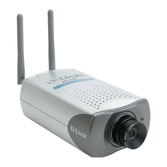
D-Link DCS-2100+ Manual
Enhanced 2.4 ghz wireless internet camera
Hide thumbs
Also See for DCS-2100+:
- Manual (143 pages) ,
- Quick installation manual (12 pages) ,
- Manual (137 pages)

Related Manuals for D-Link DCS-2100+


Summary of Contents for D-Link DCS-2100+
- Page 1 D-Link DCS-2100+ Enhanced 2.4 GHz Wireless Internet Camera Manual Version 2.0 Building Networks for People...
-
Page 2: Table Of Contents
Contents Contents of Package ................3 Introduction....................4 Features and Benefits ................4 Connections ..................6 Hardware Installation ................8 Software Installation ................9 Installing IP Surveillance Software ............13 Testing the DCS-2100+ ...............17 Security ....................18 Using and Configuring the DCS-2100+ with a NAT Router ....19 Using the DCS-2100+ with the Internet Browser ........25 Using IP Surveillance Software ............50 Monitor Program ..............50 Playback Program ..............70... -
Page 3: Contents Of Package
Package Contents ! ! ! ! ! D-Link DCS-2100+ Internet Camera ! ! ! ! ! Power Adapter ! ! ! ! ! Installation software and manual on CD ! ! ! ! ! Quick Installation Guide Camera Stand ! ! ! ! ! -
Page 4: Introduction
Introduction The D-Link DCS-2100+ Wireless Internet Camera is a powerful surveillance system that connects wirelessly to an your 802.11b network. The DCS-2100+ features enhanced 802.11b and connects wirelessly at up to 22 Mbps (Megabits per second). The DCS-2100+ differs from a conventional... -
Page 5: Web Configuration
Features & Benefits (continued) Web Configuration Using the Internet Explorer Web browser, administrators can configure and manage the Internet Camera directly from its own Web page via the Intranet or the Internet. Up to 20 user names and passwords are permitted, with privilege settings controlled by the administrator. -
Page 6: Connections
Connections Antenna Connectors Reset Button DC Power Connector Ethernet Cable Connector I/O Connector Antenna Two antennas are included with the DCS-2100+. These are screwed onto the antenna connectors on the back panel to provide a connection with a wireless network. Ethernet Cable Connector The Internet Camera’s back panel features an RJ-45 connector for connections to 10Base-T Ethernet cabling or 100Base-TX Fast Ethernet cabling. -
Page 7: Dc Power Connector
Connections (continued) DC Power Connector The DC power input connector is located on the DCS-2100+ Internet Camera’s back panel and is labeled 12VDC with a single socket to supply power to the Internet Camera. I/O Connector The DCS-2100+ provides a terminal block with two pairs of connectors situated on the back panel. -
Page 8: Hardware Installation
Hardware Installation Connect to an Ethernet Network If you are connecting the DCS-2100+ to a wired Ethernet network, connect an Ethernet cable to the network cable connector located on the Internet Camera’s back panel and attach it to the network. If you are connecting the DCS-2100+ to a 802.11b wireless Ethernet network, attach the two wireless antennas to the antenna... -
Page 9: Software Installation
Software Installation After you have successfully completed the hardware installation of the DCS-2100+ Internet Camera, it is necessary to install software to configure and operate the camera. The first step is to run the IP Installer program on the CD. IP Installer allows you to use the Internet Camera with your Internet browser. With the IP Installer program you can enter settings that permit the camera to access the Internet directly or through your Ethernet network. - Page 10 Software Installation (continued) The opening IP Installer screen will appear and show a MAC address of the DCS-2100+ and an IP Address (which may or may not be correct depending on what you have your DCS-2100+ connected to.) If you have a DHCP* server on your network, there will be a valid IP Address displayed here.
- Page 11 Software Installation (continued) If you have a DHCP server on your network, you will already have a valid IP Address in these fields. If you do not have a DHCP server on your network fill out your IP Address, Subnet mask, Gateway and at least one DNS IP Address.
- Page 12 Software Installation (continued) If you need to make any changes, click Back to modify your camera settings. To accept the settings, click Restart. Click Restart Click OK and the DCS-2100+ Internet Camera will reboot to accept the settings. If the IP Installer has not made any modifications to the settings, it will warn you that the settings were accepted but no changes were made.
-
Page 13: Installing Ip Surveillance Software
Installing IP Surveillance Software The IP Surveillance software on the CD included with the DCS-2100+ Internet Camera converts the DCS-2100+ into a powerful, yet flexible, surveillance system for home or business, with these features: ! ! ! ! ! Real-time Monitoring ! ! ! ! ! Video Recording to hard disk ! ! ! ! ! - Page 14 Installing IP Surveillance Software (continued) Click Please read the Software Licensing Agreement and click Yes if you agree with the agreement. Click No to exit the installation. Click Next Enter your name and company information and click Next.
- Page 15 Installing IP Surveillance Software (continued) Select the destination directory. Click Next Select the program folder the software will be installed into. Click Next...
- Page 16 Installing IP Surveillance Software (continued) Click Next Click Finish The installation is complete.
-
Page 17: Testing The Dcs-2100
Testing the DCS-2100+ Internet Camera Open your Internet browser and type in the IP address of the DCS-2100+. In this example the address is: http://192.168.0.146 (your DCS-2100+ may have a different IP address based on what you used in the IP Installer program.) The window in the center of your browser is the camera image window. -
Page 18: Security
Security At this point it is highly recommended that you click on the Configuration button on the Home screen, and then the Tools tab to bring you to the Admin screen. Enter a password for security purposes. To ensure the highest security and prevent unauthorized use of the Internet Camera, the Administrator has the exclusive privilege to access the System Administration settings to allow users entry and authorize privileges for all users. -
Page 19: Using And Configuring The Dcs-2100+ With A Nat Router
Materials Needed: 1 DCS-2100+ Internet Camera 1 Ethernet Cable A Wired or Wireless router such as the D-Link DI-614+ Wireless Router Ethernet based PC for system configuration SETTING UP THE DCS-2100+ FOR USE BEHIND A ROUTER Installing a DCS-2100+ Internet Camera on your network is an easy 4–step procedure: "... - Page 20 Using & Configuring the DCS-2100+ with a NAT Router (continued) This is the IP Address assigned to your camera. Write it down for later use. 192.168.0.146 is only an example. You will probably have a different IP Address. Assign a Local IP Address with IP Installer # # # # # View the Internet Camera using your Internet Explorer Web browser...
- Page 21 The following steps generally apply to any router that you have on your network. The D-Link DI-614+ is used as an example to clarify the configuration process. Configure the initial settings of the DI-614+ by following the steps outlined in the DI-614+ Quick Installation Guide.
- Page 22 Using & Configuring the DCS-2100+ with a NAT Router (continued) http://192.168.0.1 Your WAN IP Address will be listed here. Determine Your Router’s IP Address (WAN) Note: Because a dynamic WAN IP can change from time to time depending on your ISP, you may want to obtain a Static IP address from your ISP. A Static IP address is a fixed IP address that will not change over time and will be more convenient for you to use to access your camera from a remote location.
- Page 23 Using & Configuring the DCS-2100+ with a NAT Router (continued) Follow these steps to configure your router’s Virtual Server settings: Click Enabled. Select Both under Protocol Type (TCP and UDP) Enter your camera’s local IP Address (e.g., 192.168.0.146 in # # # # # the example in step above) in the Private IP field.
-
Page 24: Viewing Your Camera
Viewing Your Camera After all the router settings have been entered correctly, a PC user inside or outside your network will have access to the camera through the Internet Explorer Web browser. To access the camera from the Internet, type the IP Address of the router given to you by your ISP, followed by a colon, and the port number that you gave your camera (e.g., http://205.163.122.96:83). -
Page 25: Using The Dcs-2100+ With The Internet Browser
Using the DCS-2100+ with an Internet browser If you are following this manual in the order it is presented, you should now have an operating DCS-2100+ Internet Camera configured with the Installer program. You also have installed the IP Surveillance software from the CD. This section of the manual will deal with using the Internet Camera in two parts: Using the DCS-2100+ with an Internet browser and accessing the screens to control and monitor the camera. - Page 26 Using the DCS-2100+ with an Internet browser (continued) Home Page Screen The image from the DCS-2100+ should be visible from the Home page on your computer monitor. There are two buttons on the left side of the Home page: Connection Type Configuration.
- Page 27 Using the DCS-2100+ with an Internet browser (continued) Home > Connection Type Screen http://192.168.0.146 The following options are available from the Connection Type screen: Media Option: Allows a user to disable audio when viewing video. Protocol Option The UDP Protocol should be chosen for the most users. Generally, the client computer will automatically try these protocols in the following order, UDP ->...
- Page 28 Using the DCS-2100+ with an Internet browser (continued) Home > Configuration Click Configuration There are 5 tabs across the top of the Configuration screen. From each tab, different elements of the DCS-2100+ can be configured. The Advanced tab is the default screen in Configuration and Network is the default screen under Advanced.
-
Page 29: General Settings
Using the DCS-2100+ with an Internet browser (continued) Configuration > Advanced > Network Reset IP Address at next boot Once the DCS-2100+ is configured, this box should be unchecked at all times. If the box has been checked and the connection is lost, either run IP Installer or PING the IP Address of the camera from a command prompt to regain the connection. -
Page 30: Streaming Settings
Using the DCS-2100+ with an Internet browser (continued) Configuration > Advanced >Network Settings (continued) Streaming Settings Control channel port - It can be set to other than the default port 5001 to correspond with the port opened by the firewall. Audio channel port - It can be set to other than the default port 5002 to correspond with the port opened by the firewall. - Page 31 Using the DCS-2100+ with an Internet browser (continued) Configuration > Advanced >Network Settings (continued) Channel - The default wireless channel setting is channel 6. Select the channel that is the same as the other wireless devices on your network. TX Rate- Select the transmission rate on the network.
- Page 32 Using the DCS-2100+ with an Internet browser (continued) Configuration > Advanced > Mail & FTP Click the Mail&FTP button from the Configuration screen to access video settings that control sending images via email and FTP. SMTP SMTP (mail) server 1 - The domain name or IP address of an external mail server.
-
Page 33: Ftp Settings
Using the DCS-2100+ with an Internet browser (continued) Configuration > Advanced > Mail & FTP (Continued) FTP Settings It can be other than default port 21. If you find that Local FTP server port - you want to change the port to a port number other than 21, you will need to specify the port when connecting to the FTP server. - Page 34 Using the DCS-2100+ with an Internet browser (continued) Configuration > Advanced > Mail & FTP (Continued) 2nd FTP server - The domain name or IP address of the external FTP server. 2nd FTP user name - Granted user name on the backup FTP server. 2nd FTP password - Granted password on the backup FTP server.
- Page 35 Using the DCS-2100+ with an Internet browser (continued) Configuration > Advanced > Video Click the Video button from the Configuration screen to access video settings that affect how the video image appears. Click Video Text on video - Text will be displayed in the black bar above the video window with the timestamp.
- Page 36 Using the DCS-2100+ with an Internet browser (continued) Configuration > Advanced > Video (Continued) Power line frequency Fluorescent lights may intermittently flash depending on the AC power line frequency. Change the (for fluorescent light) frequency setting to eliminate a flashing image when the light source is fluorescent light.
- Page 37 Using the DCS-2100+ with an Internet browser (continued) Recommendations for setting video for the best performance: “Best performance” means the image refresh rate should be the fastest possible and the video quality should be the best possible at the lowest network bandwidth possible.
- Page 38 Using the DCS-2100+ with an Internet browser (continued) Recommendations for setting video for the best performance (continued): I want to compromise between real-time and clear images If you have a broadband network, set Fix quality to Good image quality, or higher, instead of setting the Bit rate.
- Page 39 Using the DCS-2100+ with an Internet browser (continued) Configuration > Advanced > Motion Detection Click the Motion Detection button from the Configuration screen to access settings that affect how the DCS-2100+ Internet Camera can serve as a security device by recording only when motion is detected. http://192.168.0.146 Click Motion Detection...
- Page 40 Using the DCS-2100+ with an Internet browser (continued) Configuration > Advanced >Motion Detection (continued) New - Click to add a new window. A maximum of three windows can be opened simultaneously. Use your mouse to drag the window frame to resize or the title bar to move.
- Page 41 Using the DCS-2100+ with an Internet browser (continued) Configuration > Tools > Admin Click on the Tools tab to access 4 utility screens for controlling and administering the DCS-2100+. The default screen in Tools is the Admin screen. The DCS-2100+ is manufactured without any passwords by default. This allows the ability to access the DCS-2100+ (including the Configuration) by anyone as long as the IP address is known.
- Page 42 Using the DCS-2100+ with an Internet browser (continued) Configuration > Tools > Admin (continued) Guest account: This option allows a user to connect to a camera with view-only privileges. User name is demo. No password is required. This is useful for demonstrations and keeps guests separate from users with accounts.
- Page 43 Using the DCS-2100+ with an Internet browser (continued) Configuration > Tools > System Keep current date and Click to save the current date and time of time - DCS-2100+. An internal real-time clock maintains the date and time even when the power is off. Sync with computer time- Synchronize the date and time of DCS-2100+ with the local computer.
- Page 44 Using the DCS-2100+ with an Internet browser (continued) Configuration > Tools > Applications Click on the Applications button to access the Applications settings from the Tools menu. http://192.168.0.146...
-
Page 45: Weekly Schedule
Using the DCS-2100+ with an Internet browser (continued) Configuration > Tools > Applications (Continued) Weekly schedule: Sunday through Saturday - Select the weekdays that should perform the following operations: Set the time to start operations. Setting the Snapshots begin at - begin time the same as the stop time will force the operations to run continuously. -
Page 46: Sequential Operation
Using the DCS-2100+ with an Internet browser (continued) Configuration > Tools > Applications (Continued) Trigger action - There are four options for two actions regarding either trigger condition. They can have multiple selections. While choosing the trigger output alarm, the digital output will short both pins to connect the circuit of the attached external device;... - Page 47 Using the DCS-2100+ with an Internet browser (continued) Configuration > Tools > Applications (Continued) FTP put snapshots with If the suffix is added, the captured date and time date and time suffix - can be easily differentiated from the snapshot file name in either sequential or event operation.
- Page 48 Using the DCS-2100+ with an Internet browser (continued) Configuration > Status > Device Info Click on the Status tab to access Device Info and a Log of DCS-2100+ system activity. The Device Info is the default screen when you click on the Status tab.
- Page 49 Using the DCS-2100+ with an Internet browser (continued) Configuration > Status > Log Click on the Log button to access a system log of system activity from the Status menu. The content of the log file reveals useful information about the current configuration and connection logged after the DCS-2100+ boots up.
-
Page 50: Using Ip Surveillance Software
Monitor program (for monitoring and recording from the DCS-2100+) from the Windows folder: Start\ Program Files\D-Link\IP Surveillance\Monitor or the directory you specified during the installation. There is also a Playback program (for accessing and playing video captured in the Monitor program.) The Playback program is detailed starting on page 70. - Page 51 Using IP Surveillance Software (continued) Control up to 16 DCS-2100+ Internet cameras from this screen. Minimum Requirements for Multiple Camera Configurations: For 1 to 4 channels: Minimum Requirements OS: MS Windows2000/XP/ME/98SE CPU: Intel 500 MHz Pentium III or above SDRAM: 128 MB SDRAM Hard Disk: 40GB For 5 to 9 channels: Minimum Requirements...
- Page 52 Using IP Surveillance Software (continued) Monitor Program Main Screen: Misc. Functions Channel Area Image Layout Area Recording Settings Hard Disk Status Video Area Features Menu & Alert Messages DI/DO Control Descriptions of the sections of the Monitor program Main screen: ! ! ! ! ! Miscellaneous functions: Including quitting the application, snapshot, full screen...
- Page 53 Using IP Surveillance Software (continued) ! ! ! ! ! Recording settings You can record video onto your hard disk. The recording schedule is configured in the Scheduler. ! ! ! ! ! Hard disk status In this area, you can get the hard disk status. This informs you of the available disk space remaining.
- Page 54 Using IP Surveillance Software (continued) Configuring a DCS-2100+ in IP Surveillance When you first login, you should configure the DCS-2100+ from the Camera Configuration screen found in the Function menu. Once you set up the administrator privilege, you can access the Camera Configuration screen. A warning message will appear to warn you that any recording that is occurring will stop when you access Camera Configuration.
- Page 55 Using IP Surveillance Software (continued) Home > Camera Configuration Screen (continued) In the Local Settings there are four main functions: Insert – To add cameras to the camera list, specify the IP address and port, click the Insert button. The program will try to connect to the DCS-2100+. If the connection succeeds, the admin password of the remote DCS-2100+ camera is required.
- Page 56 Using IP Surveillance Software (continued) Changing the Camera Order in the List You can drag and drop the gray area (fixed area) of the camera list grid to change the arrangement of cameras. This makes it easy to rearrange the cameras. Left-click in the gray area.
- Page 57 Using IP Surveillance Software (continued) Saving the Changes Once you click the Save button, the changes in the configuration will be saved and will validate immediately. Global Settings Click on the Global Settings item from the Function Menu. This area indicates backup status and last backup time...
- Page 58 Using IP Surveillance Software (continued) Reserved space – Indicates how many bytes should be reserved on the hard disk. If the recording data exceeds disk capacity, the new video data will replace the oldest data (if Cycle Recording box is checked). This space can be adjusted with the sliding bar below it.
- Page 59 Using IP Surveillance Software (continued) Check here to enable proxy. Set the proxy & port Check here to enable filter Enter IP address to add Add an IP address Delete an IP address Click If you enable proxy server and enable IP restriction, the listed IP addresses will not use the proxy.
- Page 60 Using IP Surveillance Software (continued) Adding a Channel: Adding a new camera as a channel can be accomplished with a simple drag and drop procedure. After you have inserted the camera from the Camera Configuration screen in the Function Menu, the channel number (shown below) will change from grayed out to blue (see page 55 to Insert a camera): 1.
- Page 61 Using IP Surveillance Software (continued) Stop Monitoring a Channel: To stop monitoring a video channel, you can drag and drop the video (in the video area) to the trash can. To delete a channel: 1. Select the video display of the channel to be discarded. 2.
- Page 62 Using IP Surveillance Software (continued) The Layout There are six layouts in the monitor tool. You can select (by left-clicking on the icon) which videos you want to monitor. In each layout, you can drag and drop the “channel number” to any video box in the video area. If all conditions are okay, then the video will appear in the video box, and the old video is replaced.
- Page 63 Using IP Surveillance Software (continued) Record & Schedule Record – Record the selected channel manually. Stop – Stop recording the selected channel manually. Scheduling – Arrange recording schedule Enable Scheduler – Record according to the scheduler settings. DI/DO Control Only one user with the administrator privilege can access the DI/DO control at the same time.
- Page 64 Using IP Surveillance Software (continued) If you turn on the Alert function, and a trigger is set off by motion, an alert message will show in this window. The message format is described as follows: “time”=>”alert type” #”channel number”(“win1”,”win2",”win3") For example, the message “03:47:25 PM=>MO #5(0,1,1)” means that a motion detection alert occurred at 03:47:25 PM in motion window 2 and in motion window 3.
- Page 65 Using IP Surveillance Software (continued) Miscellaneous Functions Quit – Closes the application and saves last settings. Full Screen – Switch to full screen video, double click the screen to return to the previous view. Local Time – Displays the current time. Snapshot –...
- Page 66 Using IP Surveillance Software (continued) The layout of the scheduler tool is divided into 9 sections. For ease of use, you may skip to section 7. In section 7, when you input the date, hour and minute, the times you have selected will appear in the Hour, Day, Week and Month time-lines (sections 1,2,3 and 4 illustrated here.) Section 1 of the scheduler tool is the Hour time-line.
- Page 67 Using IP Surveillance Software (continued) Current Year Settings And Camera Selector for the Recording function By default, the scheduler is running with the current date selected on the time-lines and Date-time picker. Therefore, the current scheduling year is the year that you run the scheduler tool.
- Page 68 Using IP Surveillance Software (continued) If users have configured the IP Surveillance software and the DCS-2100+ camera, the IP address and location will show the correct setting. Please note that when users switch between cameras, the changing of the schedule will be saved automatically.
- Page 69 Using IP Surveillance Software (continued) Schedule with Time Picker Remember to make the Begin Time earlier than the End Time. Otherwise the Add action will be ignored. Select period Once Every Hour Every Day Every Week After you have made your Begin Time and End Time selections, select a period.
-
Page 70: Playback Program
Using IP Surveillance Software (continued) Playback Program The Playback program is a powerful tool to assist you in browsing the recorded video database. It has two display modes (Normal display mode, Preview Mode) and three playback methods (Full Range, Time Period, Events Preview). The main tools it provides include: Powerful play control tool: •... - Page 71 Logging-In located in the main section Using IP Surveillance software. After completing the installation of IP Surveillance, you can run the Playback program from: Start\Program Files\D-Link\IP Surveillance\Playback or the directory you specified during the installation. Area Selection Indicator Control Area...
- Page 72 Using IP Surveillance Software (continued) Playback Program (continued) Display Area The display area shows the surveillance database of each camera by events triggered by an alert or by time. You can change the video size through the Display Adjustment Tool, and the playback method through the Play Control Tool.
- Page 73 Using IP Surveillance Software (continued) Playback Program (continued) Frame Selection Indicator The frame selection indicator only appears when you change the display mode to Preview Mode. It appears as a red rectangle surrounding one of the nine Event Preview Frames. Once you select one of these frames, you can control its play status through the jog dial in the control area.
- Page 74 Using IP Surveillance Software (continued) Playback Program (continued) Database path The most important item in the settings dialog is the database path setting. You must set it to the directory that contains the surveillance database to make the program work properly. AVI file location It sets the storing directory when you export AVI files.
- Page 75 Using IP Surveillance Software (continued) Playback Program (continued) Control panel position With this setting you can place the Control panel on either the left or the right of the screen. Once you change the setting of modulation or Control panel position, you have to restart the program to for these changes to take effect.
- Page 76 Using IP Surveillance Software (continued) Playback Program (continued) This color-inverted region will be the new time period the program is going to display. If you change your mind and don’t want to see that period, you can cancel it by just pressing the right button of your mouse with the left button still pressed.
- Page 77 Using IP Surveillance Software (continued) Playback Program (continued) Histogram Area The Histogram Area in the Preview Mode displays events that occurred previously as red bars, which represent the time and value of the event. Currently displayed events are represented by green bars and the selected event with blue bars.
- Page 78 Using IP Surveillance Software (continued) Playback Program (continued) Period Selector Period selector provides a precise way to choose the start time and the end time of a new period. The end time must be later than the start time. After you give the correct start and end time, clicking on the Play button in the jog dial will play the new period in the Display Area.
- Page 79 Using IP Surveillance Software (continued) Playback Program (continued) Since the program will record the previous start and end time in Time Period and Events Preview mode. Any time you want to change the period selector to see another period, you must change the Playback Method Selector to the mode you want to use first.
- Page 80 Using IP Surveillance Software (continued) Playback Program (continued) Stop When you want to stop the displaying video sequence, you can click on the Stop button. Once you have pressed the Stop button, the start point will be reset to the start of the present period. Pause The Pause button provides you a way to pause the displaying video sequence.
- Page 81 Using IP Surveillance Software (continued) Playback Program (continued) Zoom Out When you click on the Zoom Out button one time, the image size in the display area will be reduced 12.5 percent to the original size. To show the location and time information completely, the minimum zoom out ratio is limited in 0.5:1.
- Page 82 Using IP Surveillance Software (continued) Playback Program (continued) Zoom Out Each time you click on the Zoom Out button in the searching range adjustment toolbox, the displayed time period will be double in the center of the original time period unless the start time or end time exceed the database boundary. The scale of pull bar and alert histogram window changes and the period start and end time change, too.
- Page 83 Using IP Surveillance Software (continued) Playback Program (continued) The time required to Export data depends on the speed of the computer and processor that you are using. At any time during the export, you can click on the Stop button in the jog dial to stop the procedure. Then you will get an AVI file from the start time to the time you clicked the Stop button.
- Page 84 Using IP Surveillance Software (continued) Playback Program (continued) System Control Toolbox The System Control Toolbox provides basic operations for the playback program. The three elements of the system control toolbox:. Lock Window, Settings, and Quit. Lock Window To protect your computer while left unattended you can click on the Lock Window button to lock the main window.
-
Page 85: Firmware Upgrades
Firmware Upgrades The DCS-2100+ Internet Camera supports firmware upgrades (the software that controls the operation in the DCS-2100+). D-Link will supply the latest firmware version on the D-Link support Web site at: support.dlink.com. To upgrade the firmware: Download the latest firmware file from D-Link. - Page 86 Firmware Upgrades (continued) If the Upgrade Wizard finds the Internet Camera the following screen asks for the file name or gives you the choice to browse for the file. The file name should be FLASH.BIN for the DCS-2100+ Internet Camera. Click Next The firmware file is scanned by the Upgrade Wizard and the version is reported...
- Page 87 Firmware Upgrades (continued) Click Exit Warning The download firmware procedure cannot be interrupted. If the power or network connections are broken during the download procedure it might possibly cause serious damage to the Internet Camera.
-
Page 88: Appendix
Appendix Frequently Asked Questions Internet Camera Features Q: What is an Internet Camera? A: The Internet Camera is a standalone system connecting directly to an Ethernet or Fast Ethernet network. It differs from a conventional PC Camera, the Internet Camera is an all-in-one system with built-in CPU and Web-based solutions providing a low cost solution that can transmit high quality video images for monitoring. - Page 89 Q: Can the Internet Camera be setup as a PC-cam on a computer? A: No, the DCS-2100+ Internet Camera is used only on an wireless 802.11b, Ethernet or Fast Ethernet network. The D-Link DSB-C110, DSB-C310 can be used as a PC Camera (Webcam).
- Page 90 Frequently Asked Questions (continued) Q: I connected the Internet Camera directly to a computer with a cross- over cable Ethernet cable and received the following Windows error upon running IP Installer: A1: This Windows error will occur if the Internet Camera is connected to a computer that is not properly configured with a valid IP address.
-
Page 91: How To Ping Your Ip Address
Frequently Asked Questions (continued) Q: The images appear to be of poor quality, how can I improve the image quality? A1: Make sure that your computer’s display properties are set above 256 colors. Using 16 or 256 colors on your computer will produce dithering artifacts in the image, making the image appear to be of poor quality. -
Page 92: Reset And Restore
Reset and Restore There is a button hidden in the pinhole beside the Ethernet socket. It is used to reset the system or restore the factory default settings. Sometimes resetting the DCS-2100+ will return the system back to a normal state. If the system still has problems after reset, restore the factory settings and install again: RESET: 1. -
Page 93: I/O Connector
I/O Connector I/O Connector Definition for the Internet Camera The DCS-2100+ provides a general I/O terminal block with one digital input and one relay switch for device control. Pin 1 and pin 2 can be connected to an external sensor and the state of voltage will be monitored from the initial state ‘LOW’. -
Page 94: Adjusting The Camera Focus
Adjusting the Camera Focus The DCS-2100+ Internet Camera features an interchangeable C/CS-type lens that can be used for different applications as necessary. It supports rotational focus control so the lens can be adjusted to focus under normal and stable conditions to maximize the image quality of the Internet Camera. Fixed Lens Assembly Do NOT adjust Camera Lens... -
Page 95: Replacing The Lens
Replacing the Lens Since the DCS-2100+ Internet Camera is designed with a CS-mount, the lens equipped with the Internet Camera can be replaced with any standard C or CS- mount lens commonly used within the surveillance industry. Follow the instructions below to replace the supplied lens with any C or CS- mount lens. -
Page 96: Technical Specifications
Technical Specifications Remote management Camera configuration and Camera system log can be accessed remotely via Internet Explorer 5.x or above Web browser. Networking Protocol TCP/IP, HTTP, SMTP, FTP, NTP, DNS and DHCP Ethernet Enhanced 802.11b wireless or 10BaseT or 100BaseT Fast Ethernet auto-negotiation WLAN 2.4Hhz 802.11b+ DSSS CSMA/CA Protocol Bit rate: 22/11/5.5/2/1 Mbps... - Page 97 Technical Specifications (continued) LED indicator Bi-color status indicator Camera specification 1/3 inch color CMOS sensor 2.5Lux/F1.4 AGC/AWB Electronic shutter: 1/60 ~ 1/15000 second Standard CS mount type lens, 6mm, F1.8 Power 12VDC 1.5A, external power supply Weight 328 grams Dimension 160mm(L) x 83.5mm(W) x 54mm(H) Viewing system requirement Protocol...
-
Page 98: Contacting Technical Support
Technical Support Technical Support You can find software updates and user documentation on the D-Link website. D-Link provides free technical support for customers within the United States and within Canada for the duration of the warranty period on this product. -
Page 99: Time Zone Table
Time Zone Table GMT stands for Greenwich Mean Time, which is the global time that all time zones are measured from. - Page 100 Time Zone Table (continued)
-
Page 101: Warranty And Registration
Warranty Period from the date of original retail purchase. If a material defect is incapable of correction, or if D-Link determines in its sole discretion that it is not practical to repair or replace the defective Hardware, the price paid by the original purchaser for the defective Hardware will be refunded by D-Link upon return to D-Link of the defective Hardware. - Page 102 Link. Products shall be fully insured by the customer and shipped to D-Link Systems, Inc., 53 Discovery Drive, Irvine, CA 92618. D-Link will not be held responsible for any packages that are lost in transit to D-Link. The repaired or replaced packages will be shipped to the customer via UPS Ground or any common carrier selected by D-Link, with shipping charges prepaid.
- Page 103 Warranty and Registration USA only (continued) Trademarks: D-Link is a registered trademark of D-Link Systems, Inc. Other trademarks or registered trademarks are the property of their respective manufacturers or owners. Copyright Statement: No part of this publication or documentation accompanying...