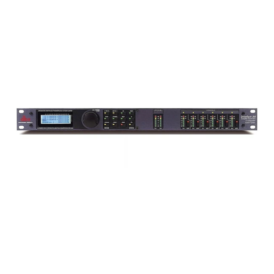
dbx DriveRack 260 User Manual
Complete equalization & loudspeaker management system
Hide thumbs
Also See for DriveRack 260:
- User manual (83 pages) ,
- Manual (2 pages) ,
- User manual (70 pages)

Related Manuals for dbx DriveRack 260


Summary of Contents for dbx DriveRack 260
- Page 1 DriveRack ® Complete Equalization & Loudspeaker Management System Featuring Custom Tunings User Manual...
-
Page 2: Important Safety Information
IMPORTANT SAFETY INFORMATION WARNING FOR YOUR PROTECTION READ THE FOLLOWING: KEEP THESE INSTRUCTIONS HEED ALL WARNINGS FOLLOW ALL INSTRUCTIONS THE APPARATUS SHALL NOT bE ExPOSED TO DRIPPING OR SPLASHING LIqUID AND NO ObjECT FILLED WITHI LIqUID, SUCH AS vASES, SHALL the symbols shown above are internationally accepted symbols that warn of bE PLACED ON THE APPARATUS. - Page 3 84070, usA date: may 19, 2010 european contact: Your local dbx sales and service office or If you want to dispose this product, do not mix it with general household waste. There is a separate collection system for used electronic products in accordance with legislation that harman music Group requires proper treatment, recovery and recycling.
-
Page 4: Table Of Contents
DriveRack ® Table of Contents Introduction 4.8 Post-Crossover PEQ ........33 4.9 Compressor/Limiter ........34 0.1 Defining the DriveRack 260 ......ii 4.10 Alignment Delay ...........37 0.2 Service Contact Info ........iii 4.11 Input Routing ..........37 0.3 Warranty ............iv 4.12 Output ............38 Section 1 - Getting Started Section 5 - Utilities/Meters 1.1 Rear Panel Connections ........2 5.1.1 LCD Contrast/Auto EQ Plot ......40... - Page 5 DriveRack ® INTRODUCTION Intro CuStoMEr SErvICE Info Defining the Driverack WArrAntY Info...
-
Page 6: Defining The Driverack 260
DriveRack 260. 0.1 Defining the DriveRack 260 System The dbx DriveRack 260 is the most effective way to manage all aspects of post mixer processing and signal routing. The DriveRack 260 essentially becomes the only device that you will need between the mixer and the power amps. -
Page 7: Service Contact Info
After expiration of the warranty, a reasonable charge will be made for parts, labor, and packing if you choose to use the factory service facility. In all cases, you are responsible for transportation charges to the factory. dbx will pay return shipping if the unit is still under warranty. -
Page 8: Warranty
In no event shall dbx or its dealers be liable for special or consequential damages or from any delay in the performance of this warranty due to causes beyond their control. -
Page 9: Section 1 - Getting Started
Section 1 DriveRack ® Getting Started... -
Page 10: Rear Panel Connections
The EU version accepts 220V-240V at frequencies from 50Hz-60Hz. Power Switch The Power Switch turns the DriveRack 260 on and off. Note: dbx Professional Products recommends that power amplifiers connected to the DriveRack 260, should be powered down prior to cycling the power on the DriveRack 260. -
Page 11: Front Panel
DriveRack ® Section 1 Getting Started 1.2 Front Panel LCD Display The backlit LCD display of the DriveRack 260 provides the user with all of the vital processing information of the DriveRack 260 including: signal routing, effect block editing and Wizard Setup functions. -
Page 12: Quick Start
DriveRack Section 1 ® Getting Started 1.3 Quick Start For those of you that wish to jump right in, the following information has been provided to act as a quick start guide for optimizing performance of the DriveRack 260. Connections When setting up the DriveRack 260, make connections as follows: •... - Page 13 DriveRack ® Section 1 Getting Started Step-by-step Setup Procedure DriveRack® User Manual...
- Page 14 DriveRack Section 1 ® Getting Started DriveRack® User Manual...
- Page 15 DriveRack ® Section 1 Getting Started DriveRack® User Manual...
- Page 16 DriveRack Section 1 ® Getting Started DriveRack® User Manual...
- Page 17 DriveRack ® Section 1 Getting Started DriveRack® User Manual...
- Page 18 DriveRack Section 1 ® Getting Started DriveRack® User Manual...
- Page 19 DriveRack ® Section 1 Getting Started DriveRack® User Manual...
- Page 20 DriveRack Section 1 ® Getting Started DriveRack® User Manual...
-
Page 21: Section 2 - Editing Functions
Section 2 DriveRack ® Editing Functions EDItIng funCtIonS... -
Page 22: Basic Navigation Modes
DriveRack Section 2 ® Editing Functions 2.1 Basic Navigation Modes Navigational aspects of the DriveRack 260 are simple and as follows. 1. FX buttons - This array of 12 FX buttons is your primary mode of directly accessing any effect module. 2. NEXT PG &... -
Page 23: Navigating The Pre-Eq Section
DriveRack ® Section 2 Editing Functions Navigating the "EQ Section" 2.3 Navigating the Pre-EQ Section (28-GEQ and PEQ) To edit the parameters of the EQs used in a selected program, simply use the following procedure. From program mode, press the EQ button to reach the EQ module to be edited. Successive presses of the EQ button will move through each channel. Navigate through the Pages of the selected EQ section by depressing "Next Page"... -
Page 24: Navigating The Other Section
DriveRack Section 2 ® Editing Functions 2.5 Navigating the Other Section Navigating the Other Section From program mode, press the Other button. Successive presses of the Other button will move you to each of the various insert modules available. Pressing the Data Wheel will select the effect parameter to be edited. OTHER <PREV PG NEXT PG>... -
Page 25: Navigating The Delay Section
the pages of selected module. Successive presses of the Data wheel will select effect parameters within the currently selected page. DriveRack ® Section 2 Editing Functions Navigating the Delay Section From program mode, press the Delay button. Pressing the Data Wheel will select the effect parameter to be edited. Navigating the Delay Section 2.7 Navigating the Delay Section Successive Presses of the Delay button will move you through pre and post crossover delays. -
Page 26: Navigating The Wizard Section
DriveRack Section 2 ® Editing Functions Navigating the WIZARD Section 2.9 Navigating the Wizard Section Navigating the WIZARD Section From program mode, press the RTA/WIZARD button. Pressing the Data Wheel will select the effect parameter to be edited. WIZARD <PREV PG NEXT PG>... -
Page 27: Section 3 - Configuration Functions
Section 3 DriveRack ® SOFTWARE ConfIgurAtIon funCtIonS... -
Page 28: Program Definition
DriveRack Section 3 ® Configuration Functions The Configuring section of the DriveRack 260 will be your key to successful navigation of the configuration functions of the DriveRack. The following information provides, descriptions about program functions and in depth configuration options of the DriveRack 260. 3.1 Program Definition The first step in understanding the programming capabilities of the DriveRack is to understand the components of a complete “program.”... -
Page 29: Editing Factory Programs
DriveRack ® Section 3 Configuration Functions Navigation Modes Once you have selected a program with a configuration that accommodates your application, the DriveRack offers instant access to edit effect types within the configuration. To instantly access an effect module, simply press the corresponding button in the button array for the desired module. -
Page 30: Saving Factory Program Changes
DriveRack Section 3 ® Configuration Functions 3.4 Saving Factory Program Changes Once you are satisfied with the changes that have been made to a factory or user program, the DriveRack allows you to save these changes to the program as a custom USER program by pressing the STORE button. -
Page 31: Creating A User Configuration
DriveRack ® Section 3 Configuration Functions 3.5 Creating a User Configuration The 260 has 25 Factory Presets in which to choose from. For some configurations, you may be able to simply select one of these presets as a starting point and edit the program from there. In the Quick Start section of this manual, you saw how you can use the Wizards to configure basic programs (i.e. - Page 32 DriveRack Section 3 ® Configuration Functions FACT • You are now in the Pre-Crossover EQ module. The upper left-hand corner of the display Program 1 indicates what EQ type is currently selected. The A and B indicators indicate which input is currently selected.
- Page 33 DriveRack ® Section 3 Configuration Functions • You are now in the Crossover module. The upper left-hand corner of the display indicates what Crossover type is currently selected. Rotate the DATA wheel to select the Crossover type. The letters ‘A’ or ‘B’ to the left of the crossover indicate a mono crossover, ‘A+B’...
-
Page 34: Saving Configuration Changes
DriveRack Section 3 ® Configuration Functions once you have exited Configuration mode. Pressing and then rotating the DATA wheel lets you link or unlink the Output Delay modules as desired. Use the PREV PG and NEXT PG buttons to move through outputs 1-6, allocating delay and linking/unlinking modules as necessary, then to the next module screen which will appear something like this: NAME: Output Ch2 DLY 20 MS... -
Page 35: Section 4 - Detailed Parameters
Section 4 DriveRack ® PARAMETERS DEtAILED PArAMEtErS... -
Page 36: Pre-Crossover Eq (28 Band Graphic Or 9-Band Parametric)
DriveRack Section 4 ® Detailed Parameters The DriveRack 260 offers complete editing flexibility, by offering in-depth control over every parameter within each effect module. The following section will provide you with descriptions and explanations of all parameters within the DriveRack 260. 4.1 Pre-Crossover EQ (28 Band Graphic or 9-Band Parametric) The DriveRack 260’s Pre-Crossover EQ section may be configured as a single or linkable 28 band graphic EQ or 9-Band Parametric EQ. -
Page 37: Feedback Eliminator (Afs)
DriveRack ® Section 4 Detailed Parameters Band 9 Frequency 20 to 20k (High Shelf) Selects the frequency of the high shelf parametric EQ. Slope 9 3-12dB/Octave Sets the slope of the high shelf parametric EQ. Level 9 -12 to 12 dB Sets the overall gain of the high shelf parametric 4.2 Feedback Eliminator The DriveRack 260 offers the exclusive patent pending AFS (Advanced Feedback Suppression) -
Page 38: Subharmonic Synthesizer
DriveRack Section 4 Section 4 ® Detailed Parameters creating feedback. FIXED mode is used before the performance without any input signal. In LIVE mode, the live filters automatically detect and remove feedback during the performance. When all of the live filters have been used, they begin to round robin. Essentially this means that the first filter set is replaced where a new feedback is detected and notched out. -
Page 39: Noise Gate
DriveRack ® Section 4 Detailed Parameters Sub-Harmonics Synth - 0 to 100% This parameter sets the overall level of the Subharmonic Synthesizer. 24-36Hz and 36-56Hz (Subharmonic Synthesis) Level - 0 to 100% These controls individually let you customize the amount of the respective synthesized frequencies to be added in, tuning the ultimate bass response of your system to taste. -
Page 40: Automatic Gain Control (Agc)
DriveRack Section 4 Section 4 ® Detailed Parameters 4.5 Automatic Gain Control (AGC) The AGC is used to keep the average level of a signal at a constant level. This is done by selecting a desired Target output level and Window. The AGC keeps the signal within the Window about the selected Target by slowly adjusting the gain. -
Page 41: Notch Filters
DriveRack ® Section 4 Detailed Parameters 4.6 Notch Filters The notch filter is the perfect tool for dropping out undesirable frequencies that may appear in the input signal. Up to six Notch filters are available for all six outputs. Notch On/Off Turns the notch filters on and off. -
Page 42: Compressor/Limiter
DriveRack Section 4 Section 4 ® Detailed Parameters Type This parameter selects the PEQ band type. Types include: Bell - All bands are bell-shaped. • HShelf - One band is a high shelf, while all others are bell. • LShelf - One band is a low shelf, while all others are bell. •... - Page 43 DriveRack ® Section 4 Detailed Parameters compression to choose from (1 being almost hard knee and 10 being the softest (most gradual) knee). This lets you choose the exact knee that is needed for the dynamic effect you are looking for.
- Page 44 DriveRack Section 4 Section 4 ® Detailed Parameters LIMITER Limiter On/Off Turns the Limiter module on and off. OverEasy (O) Off to 10 There are ten levels of OverEasy® that can be used for the limiters. The point when the limiter starts to limit is the “knee.”...
-
Page 45: Alignment Delay
DriveRack ® Section 4 Detailed Parameters than the overshoot amount, and that it will not introduce harsh artifacts. The second stage is a unique program limiter featuring Intelligent Predictive Limiting™. Its function is to monitor the input signal and intelligently predict the amount of gain reduction needed to keep the output signal below the ceiling set by the Instantaneous Transient Clamp™. -
Page 46: Output
DriveRack Section 4 ® Detailed Parameters Input 1 Level -Inf to 20dB Adjusts the input level of input 1. Input 2 Level -Inf to 20dB Adjusts the input level of input 2. Master level -Inf to 20dB This parameter is used to control the overall level of the mixed input signals. Pink Noise On/Off Turns the pink noise generator on and off. -
Page 47: Section 5 - Utilities/Meters
Section 5 DriveRack ® Utilities/Meters utILItIES/ MEtErS SECtIon... -
Page 48: Lcd Contrast/Auto Eq Plot
DriveRack Section 5 ® Utilities/Meters The Utility section of the DriveRack 260 gives you the ability to perform several key operational functions to the DriveRack including: Security settings, Power-up features, Program list visibility, Auto EQ plotting and Display contrast settings. Additionally, pressing and holding the Utility button will allow you to enter the metering section of the 260. -
Page 49: Zc Setup
Output 5.1.3 ZC Setup A unique feature of the DriveRack 260 is its ability to interface with dbx proprietary Zone Controller wall-panels. This feature gives you the ability to control various parameters of the 260 such as Output Levels, Mute and Program Changes. Up to six ZC panels can be connected to a DriveRack 260. - Page 50 DriveRack Section 5 ® Utilities/Meters • If any ZCs are currently connected and their dip switches properly set, the display will read ‘Panel Detected’ for any such corresponding Panel (ID) numbers. Rotate the DATA wheel to select the desired Panel (ID) number (options are 1-6). Once the panel to edit has been selected, press the STORE button.
-
Page 51: Security
Panel 1 ZC-3 DriveRack Select A ® Section 5 No Change Utilities/Meters Panel 1 ZC-4 Switch No Change Pressing and then rotating the DATA wheel will allow you to first select the latch switch • combination in binary. Pressing the DATA wheel again and rotating it then allows you to assign this binary switch combination to a program to be loaded. - Page 52 DriveRack Section 5 ® Utilities/Meters When the Security Level function parameter is selected, rotating the DATA wheel is • used to select which function you would like to set the security for. Items include: Program Changes, Program List, Mutes, Store, Inputs, Pre EQ, Insert 1, Insert 2, Pre Delay, Crossover, Post EQ, Dynamics, Post Delay and Outputs.
-
Page 53: Program List/Program Change
DriveRack ® Section 5 Utilities/Meters Use the PREV PG or NEXT PG buttons to move to the security page that appears as • follows: Set Security Level Set 260 Device Level Password Pre EQ High Edit High Password Edit Med Password Set Security Level Set 260 Device Level Password... - Page 54 DriveRack Section 5 ® Utilities/Meters The procedure for setting up the program list is as follows. • From Program mode, press the UTILITY button and use the PREV PG or NEXT PG buttons to move to the page that appears something like this: ssword Program List Prog Change Mode...
-
Page 55: Meters
DriveRack ® Section 5 Utilities/Meters 5.2.1 - Meters To meter various aspects of the 260, press and hold the UTILITY button until the display enters the Metering section. Use the PREV PG or NEXT PG button to move to the page that appears as follows: •... -
Page 57: Section 6 - Remote Control
Section 6 DriveRack ® remote Control DriveWare ™ Zone Controllers... -
Page 58: Driveware™ Pc Software Gui
® Remote Control To make operation of the DriveRack 260 even more convenient, dbx includes the option of using the DriveRack PC GUI software (DriveWare™) and/or Zone Controllers (sold separately). The following section contains some basic information regarding the utilization of the DriveWare™... - Page 59 Remote Control CONNECTION • Connect the supplied dbx Null Modem cable between the computer’s RS-232 port and DriveRack’s PC (RS-232) port. The cable must be wired like this: DB-9 female-to-female null modem cable Important Note! A straight through RS-232 cable will not work with the DriveRack.
- Page 60 DriveRack SECTION 6 ® Remote Control BASIC OPERATION • Double left click on the DriveRack 260 icon in the upper left-hand corner of the main DriveWare window. • You will now see your 260 device Edit Window where you can program and control the DriveRack 260 device.
- Page 61 DriveRack ® SECTION 6 Remote Control • To enter the Utility Menu, Right-Click-hold on the top bar of the program edit window. Select ‘Utilities’ from the menu items list. The Utility Menus will appear as follows: For more comprehensive information on using DriveWare, please visit the Training section and FAQs section at www.dbxpro.com.
-
Page 62: Zc-Zone Controllers
RJ-45 connectors, the Zone Controllers offer an easy to program and use remote control surface. ZC REMOTE DESCRIPTION The following describes the functions of each dbx ZC remote wall panel. ZC-1 The ZC-1 is a programmable zone controller that allows output volume level control from a wall panel. - Page 63 DriveRack ® SECTION 6 Remote Control ZC-1 & ZC-2 1. Select the ‘Panel’ number (this must match the Dip Switch setting (ID#) set on the ZC wall panel). 2. Select a ZC-1 (or ZC-2 if using a ZC-2) as the ‘Type’. 3.
- Page 64 DriveRack SECTION 6 ® Remote Control ZONE CONTROLLER WIRING The DriveRack 260 Zone Controllers, (ZC-1, ZC-2, ZC-3, ZC-4) can be wired serially or in parallel. To wire in series each Zone Controller must have an identification or zone number chosen using the DIP switches on the side of the controller (see diagram A).
- Page 65 DriveRack ® SECTION 6 Remote Control Diagram C ZC-BOB ZC-1 ZC-2 ZC-3 ZC-4 DriveRack® User Manual...
- Page 66 Cable runs of up to 1,000 feet may be achieved using “Home Run” wiring. An example of this is shown in Diagram C. A dbx Zone Controller Break Out Box (dbx ZC-BOB) is used to parallel several cable runs (up to six).
-
Page 67: Section 7 - Application Guide
Section 7 DriveRack ® APPLICAtIon guIDE... -
Page 68: Mono 4-Way W/ 2 Aux Zones
4. Using the Utility Menu, select the ID for each ZC-1 and ZC-2 Zone Controller and program its output level boost and cut parameters. Left Right JBL AE Series AC2215/64 dbx ZC-1 dbx ZC-2 JBL Control 26C JBL Control 26C Ceiling Speaker Ceiling Speaker... -
Page 69: Stereo Tri-Amp
DriveRack ® Section 7 Application Guide 7.2- Stereo Tri-amp Hardware 1. Connect the outputs from the mixer to the inputs of the DriveRack. 2. Connect the outputs of the DriveRack and run to the selected speaker amplifier. 3. Making sure that all outputs are muted, apply power to the mixer and amplifiers. Software 1. -
Page 70: Stereo W/ Four Aux Zones
6. Using the Utility Menu, select the ID for the ZC-3 Zone Controller and select the programs that the ZC-3 will load from each of its positions. Left Right dbx ZC-3 MA-5002VZ dbx ZC-1 dbx ZC-2 dbx ZC-1... -
Page 71: Stereo Bi-Amp W/ Dual Delays
3. Adjust the individual parameters for the system by pressing the Processing Module buttons. 4. Using the Utility Menu, select the ID for each ZC-1 and ZC-2 Zone Controller and program its output level boost and cut parameters. Left Right dbx ZC-2 MA-5002VZ JBL Control 25 Zone A JBL AE Series AM6315/95... -
Page 73: Appendix
Appendix DriveRack ®... -
Page 74: Factory Reset
DriveRack Appendix A ® Appendix A.1 Factory Reset In the event that a reset is required, the DriveRack 260 offers you the option of performing a “Soft” or “Hard” reset. The Soft Reset resets all operating parameters except user programs. The Hard Reset Procedure will reset all programmable information back to the factory defaults. -
Page 75: Specifications
Alignment Delay: Total of 2.7 seconds available for allocation amongst all delay modules (1.3 seconds maximum delay time) A/D Performance: Type: dbx Type IV conversion system Dynamic Range: >107 dB unweighted, >110 dB A-weighted Type IV dynamic range: 123 dB with transient material, A-weighted, 22kHz BW 121 dB with transient material, unweighted, 22kHz BW 115... -
Page 76: Auto Eq Optimization
DriveRack Appendix A ® Appendix A.4 Auto EQ Optimization Tips By using the System Setup Wizard, crossover parameters, post-crossover parametric EQ and, in some cases, driver alignment delay settings are set to match your system. The Auto-EQ can be used to adjust your system to compensate for room effects, and adjust the response of the entire system to your liking. -
Page 77: Crossover Diagrams
DriveRack ® Appendix A Appendix A.5 Crossover Diagrams 1X1(1-band) 1X2(2-band) 1X3(3-band) 1X4(4-band) 1X6(4-band) 1X5(4-band) 2X3(2-band) L Mono 2X5 (3-band) 2X4(2-band) 2X6 (3-band) L Mono DriveRack® User Manual... -
Page 78: Program List/ Speaker Tunings/ Power Amp Tunings
DriveRack Appendix A ® Appendix A.6 Program List/ Speaker Tunings/ Power Amp Tunings Program List Main Speakers Power Amplifiers AM6340/95 MP418S FRZ250z XLS 202 User Factory Program Name AM6340/64 MP418SP Elim i XLS 402 2x3w/3Zones AM6315/95 MRX512M Elim iS XLS 602 PowerTech 1.1 LCRw/Cluster AM6315/64... -
Page 79: Block Diagram
DriveRack ® Appendix A Appendix A.7 Block Diagram DriveRack® User Manual... -
Page 80: Input And Output Section Diagrams
DriveRack Appendix A ® Appendix A.8 Input and Output Diagrams XLR 1 Input 1 Gain DSP Input 1 Input 2 Gain Input 1 Gain XLR 2 DSP Input 2 Input 2 Gain Euroblock DriveRack® User Manual... -
Page 81: Gain Level Jumpers
DriveRack ® Appendix A Appendix A.9 Gain Level Jumpers CAUTION: These servicing instructions are for use by qualified service personnel only. To reduce the risk of electric shock, do not perform any servicing other than that contained in the operating instructions unless you are qualified to do so. - Page 82 DriveRack Appendix A ® Appendix One thing that is critical to system setup is maximizing gain structure. Gain structure refers to aligning the gain of each device so that they all clip at the same point, and the noise floor of the entire system is at its absolute minimum.
- Page 84 8760 South Sandy Parkway Sandy, Utah 84070 Phone: (801) 568-7660 Fax (801) 568-7662 Int’l Fax: (801) 568-7583 Questions or comments? E-mail us at: customer@dbxpro.com or visit our World Wide Web home page at: www.dbxpro.com 18-1796V-E Printed in China...