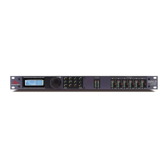
dbx DriveRack 260 User Manual
Complete equalization & loudspeaker management system
Hide thumbs
Also See for DriveRack 260:
- User manual (84 pages) ,
- Manual (2 pages) ,
- User manual (83 pages)

Related Manuals for dbx DriveRack 260


Summary of Contents for dbx DriveRack 260
- Page 1 ® Complete Equalization & Loudspeaker Management System Featuring Custom Tunings User Manual...
-
Page 2: Important Safety Instructions
IMPORTANT SAFETY INSTRUCTIONS WARNING FOR YOUR PROTECTION C A U T I O N PLEASE READ THE FOLLOWING: R I S K O F E L E C T R I C S H O C K D O N O T O P E N KEEP THESE INSTRUCTIONS A T T E N T I O N : R I S Q U E D E C H O C E L E C T R I Q U E - N E P A S O U V R I R... -
Page 3: Electromagnetic Compatibility
IMPORTANT SAFETY INSTRUCTIONS U.K. MAINS PLUG WARNING A molded mains plug that has been cut off from the cord is unsafe. ELECTROMAGNETIC Discard the mains plug at a suitable disposal facility. NEVER UNDER ANY CIRCUMSTANCES SHOULD YOU INSERT A DAMAGED OR CUT COMPATIBILITY MAINS PLUG INTO A 13 AMP POWER SOCKET. -
Page 4: Table Of Contents
™ DriveRack Table of Contents Introduction 4.8 Post-Crossover PEQ........33 4.9 Compressor/Limiter ........34 0.1 Defining the 260 DriveRack ......ii 4.10 Alignment Delay...........37 0.2 Service Contact Info........iii 4.11 Input Routing..........37 0.3 Warranty............iv 4.12 Output ............38 Section 1 - Getting Started Section 5 - Utilities/Meters 1.1 Rear Panel Connections ........2 5.1.1 LCD Contrast/Auto EQ Plot ......40 1.2 Front Panel ............2... - Page 5 ™ DriveRack INTRODUCTION INTRO CUSTOMER SERVICE INFO Defining the DriveRack WARRANTY INFO ®...
-
Page 6: Defining The 260 Driverack
• Independent Input and Output Processing • Auto-EQ Function • Full Bandpass, Crossover, and Routing Configurations • Auto Gain Control • Pink Noise Generator and full-time RTA • Setup Wizard with JBL ® and Crown ® Components • Security Lockout •... -
Page 7: Service Contact Info
™ DriveRack Introduction In addition to the amazing menu of processors available, the 260 also affords you the luxury of utilizing dbx Zone-Controller series wall-mounted control panels that will allow you to remote- ly control various parameters of the 260. The ZC-1 offers remote programmable Volume con- trol to any installation using the DriveRack™... -
Page 8: Warranty
™ DriveRack Introduction 0.3 Warranty This warranty is valid only for the original purchaser and only in the United States. 1. The warranty registration card that accompanies this product must be mailed within 30 days after purchase date to validate this warranty. Proof-of-purchase is considered to be the bur- den of the consumer. - Page 9 Section 1 ™ DriveRack Getting Started ®...
-
Page 10: Section 1 - Getting Started
™ DriveRack Section 1 Getting Started 1.1 Rear Panel Connections IEC Power Cord Receptacle The DriveRack 260 comes with a power supply that will accept voltages ranging from 100V- 120V at frequencies from 50Hz-60Hz. An IEC cord is included. EU version accepts 220V-240V at frequencies from 50Hz-60Hz. - Page 11 ™ DriveRack Section 1 Getting Started LCD Display The backlit LCD display of the DriveRack 260 provides the user with all of the vital processing information of the DriveRack 260 including: signal routing, effect block editing and Wizard Setup functions. The display will also notify the user if any internal clipping is taking place within the unit by displaying “CLIP”...
-
Page 12: Quick Start
™ DriveRack Section 1 Getting Started Output Meters The DriveRack 260 provides the user with six independent six-segment Lightpipe™ output meters that range from -30 to +22 dBu. 1.3 Quick Start For those of you that wish to jump right in, the following information has been provided to act as a quick start guide for optimizing performance of the DriveRack 260. - Page 13 ™ DriveRack Section 1 Getting Started of the signal path from the input to the output section. The features of the front panel of the DriveRack 260 are as follows from left to right. LCD Display- All operational information of the 260 DriveRack is displayed here. The display will also notify the user if any internal clipping is taking place within the unit.
- Page 14 Main Speaker Select Main PA JBL SRX >SR4702X Passive • Rotate the <Data> wheel to select any one of the numerous custom-tuned MAIN speaker options available. If the speaker being used is not specified in the menu, select CUSTOM.
- Page 15 ™ DriveRack Section 1 Getting Started Sub Speaker Select Sub PA >None • Rotate the <Data> wheel to select any one of the numerous custom-tuned SUB speaker options available. Once you have selected your SUB speaker option, press the <NEXT PG> button and the display will appear as fol- lows: High Amplifier Select an amplifier...
- Page 16 ™ DriveRack Section 1 Getting Started • Once you have completed your amp level settings, you will press the <NEXT PG> button, where you will be asked to select a bridged or normal setting fro your low amp (if used). The display will appear as follows: •...
- Page 17 ™ DriveRack Section 1 Getting Started to. Be certain to raise the pink noise level to the level to be used during the perfor- mance. Once the Pink level has been adjusted to the desired volume. The mic level indicator will register the signal level. Press the <NEXT PG> button and the Auto EQ sequence will begin.
- Page 18 ™ DriveRack Section 1 Getting Started ton and the display will read: F F F F F F L L L L L L Select total number of AFS filters. • You will now use the <DATA> wheel to select the number of fixed filters. This will range from values 0-12.
- Page 19 ™ DriveRack Section 1 Getting Started F F F F F F L L L L L L Slowly Increase the mixer gain to desired level. • You are now prompted to raise the output gain of the mixer to the level of the per- formance.
- Page 20 ™ DriveRack Section 1 Getting Started ®...
-
Page 21: Section 2 - Editing Functions
Section 2 ™ DriveRack Editing Functions EDITING FUNCTIONS ®... -
Page 22: Basic Navigation Modes
™ DriveRack Section 2 Editing Functions Editing Functions 2.1 Basic Navigation Modes Navigational aspects of the 260 DriveRack is simple and as follows. 1. FX buttons - This array of 12 FX buttons is your primary mode of directly accessing any effect module. 2. NEXTPG &... -
Page 23: Navigating The Pre-Eq Section
™ DriveRack Section 2 Editing Functions STORE(Delete) - The store button is used to store program edits.When pressed and held, the 260 will enter the PROGRAM DELETE module. RTA (Wizard) - This enters the RTA mode, or when held, enters the 260 DriveRack Wizard setup menu which includes: System Setup, Auto EQ setup and AFS Wizard. -
Page 24: Navigating The Other Section
™ DriveRack Section 2 Editing Functions 2.5 Navigating the Other Section From program mode, press the Other button. Successive presses of the Other button will move you to each of the various insert modules available. Pressing the Data Wheel will select the effect parameter to be edited. OTHER <PREV PG NEXT PG>... -
Page 25: Navigating The Delay Section
™ DriveRack Section 2 Editing Functions 2.7 Navigating the Delay Section From program mode, press the Delay button. Pressing the Data Wheel will select the effect parameter to be edited. Successive Presses of the Delay button will move you through pre and post crossover delays. DELAY DELAY Delay - On/Off... -
Page 26: Navigating The Wizard Section
™ DriveRack Section 2 Editing Functions 2.9 Navigating the Wizard Section From program mode, press the RTA/WIZARD button. Pressing the Data Wheel will select the effect parameter to be edited. WIZARD <PREV PG NEXT PG> SYSTEM SETUP Sub Speaker Select- GEQ Setup-Dual Mono Main Speaker Select- Insert 1 Setup-... - Page 27 Section 3 ™ DriveRack SOFTWARE CONFIGURATION FUNCTIONS ®...
-
Page 28: Program Definition
™ DriveRack Section 3 Configuring the DriveRack™ The Configuring section of the 260 DriveRack will be your key to successful navigation of the configuration functions of the DriveRack. The following information provides, descriptions about program functions and in depth configuration options of the 260 DriveRack. 3.1 Program Definition The first step in understanding the programming capabilities of the DriveRack is to understand the components of a complete “program.”... -
Page 29: Editing Factory Programs
™ DriveRack Section 3 Configuring the DriveRack™ Navigation Modes Once you have selected a program with a configuration that accommodates your application, the DriveRack offers instant access to edit effect types within the configuration. To instantly access an effect module, simply press the corresponding button in the button array for the desired module. -
Page 30: Saving Factory Program Changes
™ DriveRack Section 3 Configuring the DriveRack™ 3.4 Saving Factory Programs Changes Once you are satisfied with the changes that have been made to a factory or user program, the DriveRack allows you to save these changes to the program as a custom USER program by pressing the STORE button. -
Page 31: Creating A User Configuration
™ DriveRack Section 3 Configuring the DriveRack™ 3.5 Creating a User Configuration User Configuration is an ideal feature available in the 260 DriveRack. Even with the versatility of the Factory configurations within the DriveRack, there may be an application that requires a unique “custom”... - Page 32 ™ DriveRack Section 3 Configuring the DriveRack™ B modules. Note that the same EQ types must be selected to link. Use the PREV PG and NEXT PG buttons to move through A and B, and then to the next module screen which will appear something like this: COMP Select...
- Page 33 ™ DriveRack Section 3 Configuring the DriveRack™ POST EQ Link/Unlink • You are now in the Post-Crossover EQ module. The arrow indicates that EQ type is selected. Rotate the DATA wheel to select the Parametric EQ type. Use the PREV PG and NEXT PG buttons to move through outputs 1-6, and then to the next mod- ule screen which will appear something like this: LIMITER...
-
Page 34: Saving Configuration Changes
™ DriveRack Section 3 Configuring the DriveRack™ NAME: Output Ch2 <DATA> - SELECT CHARACTER <PREV/NEXTPG> - LEFT/RIGHT <STORE>-EDIT/<UTIL>-EXIT • Once all of the naming assignments have been made, press the UTILITY button to return to Configuration mode. If all Configuration modifications you can press the PROGRAM button to return to program mode where you will proceed to Store your new USER configuration. -
Page 35: Section 4 - Detailed Parameters
Section 4 ™ DriveRack PARAMETERS DETAILED PARAMETERS ®... -
Page 36: Pre-Crossover Eq (31 Band Graphic) Or (9-Band Parametric)
™ DriveRack Section 4 Section 4 Detailed Parameters The 260DriveRack offers complete editing flexibility, by offering in-depth control over every parameter within each effect module. The following section will provide you with descriptions and explanations of all parameters within the 260 DriveRack. 4.1 Pre-Crossover EQ The 260 DriveRack’s Pre-Crossover EQ section may be configured as a single or linkable 28 band graphic EQ or 9-Band PEQ. -
Page 37: Feedback Eliminator (Afs)
™ DriveRack Section 4 Detailed Parameters Slope 9 3-12dB/Octave Sets the slope of the high shelf parametric EQ. Level 9 -12 to 12 dB Sets the overall gain of the high shelf parametric 4.2 Feedback Eliminator The 260 DriveRack offers the exclusive patent pending AFS (Advanced Feedback Suppression) feedback elimination module. -
Page 38: Subharmonic Synthesizer
™ DriveRack Section 4 Section 4 Detailed Parameters is replaced where a new feedback is detected and notched out. This mode is useful because feedback frequencies may change as the microphone is moved, and/or as the characteristics of the venue change. Note- Only the fixed filter settings will be stored with the new program. Type - Speech, Low Music, Medium Music and High Music If Fixed or Live mode is chosen, the text will read “Type.”... -
Page 39: Noise Gate
™ DriveRack Section 4 Detailed Parameters 24-36Hz and 36-56Hz (Subharmonic Synthesis) Level - 0 to 100% These controls individually let you customize the amount of the respective synthesized fre- quencies to be added in, tuning the ultimate bass response of your system to taste. For example, if the sound is too woofy or growly, try turning down the 36Hz-56Hz level. -
Page 40: Automatic Gain Control (Agc)
™ DriveRack Section 4 Section 4 Detailed Parameters 4.5 Automatic Gain Control (AGC) The AGC is used to keep the average level of a signal at a constant level. This is done by selecting a desired Target output level and Window. The AGC keeps the signal within the Window about the selected Target by slowly adjusting the gain. -
Page 41: Notch Filters
™ DriveRack Section 4 Detailed Parameters 4.6 Notch Filters The notch filter is the perfect tool for dropping out undesirable frequencies that may appear in the input signal. Up to six Notch filters are available for all six outputs. Notch On/Off Turns the notch filters on and off. -
Page 42: Compressor/Limiter
™ DriveRack Section 4 Section 4 Detailed Parameters Flatten/Restore This parameter either flattens the PEQ or restores the PEQ to its original shape. Type This parameter selects the PEQ type. Types include: 1. Bell-All parametrics are bell-shaped 2. HShelf - One shelf is High, while all others are bell 3. LShelf - One shelf is Low, while all oth- ers are bell and 4. - Page 43 ™ DriveRack Section 4 Detailed Parameters Threshold (T) -40 to +20dBu Threshold is the signal level at which the unit starts to compress the signal. If the level is set to -10 dBu, than any signal larger than -10 dBu is compressed while any signal that has a level that is lower than -10dBu is left at the same signal level.
- Page 44 ™ DriveRack Section 4 Section 4 Detailed Parameters OverEasy (O) Off to 10 There are ten levels of OverEasy® that can be used for the limiters. The point when the com- pressor starts to compress is the "knee." When the compressor starts to reduce the level of a signal abruptly as it passes over the threshold this is called "hard knee"...
-
Page 45: Alignment Delay
™ DriveRack Section 4 Detailed Parameters reduction needed to keep the output signal below the ceiling set by the Instantaneous Transient Clamp™. Note that since the PeakStop+™ limiter is a fail-safe limiter, it must come after the OUTPUT GAIN control. Overshoot 1-6 This parameter sets the amount of overshoot for the Instantaneous Transient Clamp™. -
Page 46: Output
™ DriveRack Section 4 Detailed Parameters Noise Level -10 to 10 (Mixer and Router) Adjusts the overall level of the pink noise generator. 4.12 Output The output section 480, 481 and 482 DriveRack™ units provide the user with the ability to con- trol output levels of the unit and adjust phase compensation of loudspeakers within the signal path. - Page 47 Section 5 ™ DriveRack Utilities/Meters UTILITIES/ METERS SECTION ®...
-
Page 48: Section 5 - Utilities/Meters
™ DriveRack Section 5 Utilities/Meters The Utility section of the 260 DriveRack gives you the ability to perform several key operational functions to the DriveRack including: Security settings, Power-up features, Program list organi- zation, Auto EQ plotting, adjustment of Output Jumper settings and Display contrast settings. Additionally, pressing and holding the utility button will allow you to enter the metering sec- tion of the 260. -
Page 49: Zc Setup
™ DriveRack Section 5 Utilities/Meters Current: After cycling the power (or power failure), the unit will automatical- ly reload a configuration exactly as it was prior to powering down. This includes any adjustments made to any effect modules including: delays, EQs... etc. -
Page 50: Security
™ DriveRack Section 5 Utilities/Meters Panel 1 ZC-2 Boost 0dB Cut Output • Pressing the DATA wheel will give you the option of selecting the range of the boost and the cut of the potentiometer on the ZC-2 or ZC-2. Once the boost and cut range has been selected, pressing (select) and rotating the DATA wheel will let you select any one of the six outputs to be affected by the boost and cut control. - Page 51 ™ DriveRack Section 5 Utilities/Meters different levels of access, this ensures limited access to different users. This security system also allows you to create unique passwords which will limit/prevent any other users from access to the system. The following infor- mation is provided to help you set all security parameters.
- Page 52 ™ DriveRack Section 5 Utilities/Meters Password Edit High Password Edit Med Password Press Store to Change • Press the DATA wheel to select password to edit. When the level password has been selected, press the store button to select a name. The display will appear as follows: NAME: ROCK VENUE <DATA>...
-
Page 53: Program List/Program Change
™ DriveRack Section 5 Utilities/Meters • Once you have entered your security password, press the STORE button to store the password and the clearance level will be changed. To abort this procedure at any time, press PROGRAM/CONFIG button. • Press the PROGRAM/CONFIG button to return to normal operation. •... -
Page 54: Output Jumper Switches
™ DriveRack Section 5 Utilities/Meters • To set the program number that will correspond with the index number, press the DATA wheel. once this is selected, rotate the DATA wheel to select the desired program number. • Once your program list has been built, press the PROGRAM/CONFIG button to exit. Program lock means that program numbers below the selected number cannot be overwrit- ten. -
Page 55: Meters
™ DriveRack Section 5 Utilities/Meters 5.2.1 - Meters To meter various aspects of the 260, press and hold the UTILITY button until the display enters the Metering section. • Use the PREV PG and NEXT PG button to move to the page that appears as follows: INS COMP o+ -30-20 0 +20... - Page 56 ™ DriveRack Section 5 Utilities/Meters • Use the PREV PG and NEXT PG button to move to the page that appears as follows: Output Trims Trim 0.0 Net 0.0 dB Trim 0.0 Net 0.0 dB Trim 0.0 Net 0.0 dB This (as well as the following) page show the amount of Trim and Net Reduction within the output section.
-
Page 57: Section 6 - Remote Control
Section 6 ™ DriveRack Remote Control DriveWare ™ ZC-Remote Zone Controllers ®... -
Page 58: Pc Gui Installation
™ DriveRack SECTION 6 Remote Control To make operation of the DriveWare™ units even more convenient, dbx professional prod- ucts includes the option of using the DriveRack PC GUI software (included) and the ZC- Remote Controllers (optional). The following section contains some basic information regarding the utilization of the DriveWare software including: install, system requirements, cable specifications and basic operation and basic setup for ZC-Remote Controller applica- tions. - Page 59 ™ DriveRack SECTION 6 Remote Control The utility menus will appear as follows: • To customize the mode of operation to best suit your needs, it is recommended that at this point, you set your desired preferences in the preference folder, which can be accessed in the file menu and will appear as follows: ®...
-
Page 60: Cable Specs
™ DriveRack SECTION 6 Remote Control Note: The Baud rate must be set to 38400. GUI Recommended Cable Specifications: PC GUI Interface - DB-9 female-to-female nul modem cable. (10 feet) ® DriveRack™ User Manual... -
Page 61: Zc-Zone Controllers
™ DriveRack SECTION 6 Remote Control 6.2.1 ZC-Zone Controllers Zone Controller Installation The installation of the Zone Controllers MUST be accomplished with the use of cable which is rated VW-1 or higher. Common NEC designations which meet this rating include: CMP, CMR, CMG, CM and CMX. - Page 62 ™ DriveRack SECTION 6 Remote Control ® DriveRack™ User Manual...
- Page 63 ™ DriveRack SECTION 6 Remote Control Zone Controller Wiring The DriveRack 260 Zone Controllers, (ZC-1, ZC-2, ZC-3, ZC-4) can be wired serially or in par- allel. To wire in series each Zone Controller must have an identification or zone number cho- sen using the DIP switches on the side of the controller (see diagram A).
-
Page 64: Remote Control
™ DriveRack SECTION 6 Remote Control Diagram C Cable Specification: Cat 5 Cable - 4-Twisted Pairs of 24 AWG wire RJ-45 RJ-45 (8-Position) (8-Position) White/Orange -VREF Orange -Zone 1 White/Green -Zone 2 Green -Zone 3 White/Blue -Zone 4 Blue -Zone 5 White/Brown -Zone 6 Brown... - Page 65 ™ DriveRack SECTION 6 DriveWare Functions 6.2.2 Note - The following cable lengths were achieved using Cat5 Enhanced cable exhibiting a max- imum D.C. resistance of 29 Ohms per 1,000 feet. When connecting Zone Controllers in series, the following cable length restrictions apply: As shown in Diagram A, any (3) Zone Controllers may be wired in series as long as the total cable length does not exceed 600 feet.
-
Page 67: Section 7 - Application Guide
Section 7 ™ DriveRack APPLICATION GUIDE ®... -
Page 68: Stereo W/ 4 Aux Zones
3. Adjust the individual parameters for the system by pressing the Processing Module buttons. 4. Using the Utility Menu, select the ID for each ZC-1 and ZC-2 Zone Controller and program its output level boost and cut parameters. Left Right JBL AE Series AC2215/64 dbx ZC-1 dbx ZC-2 JBL Control 26C... -
Page 69: Stereo Tri-Amp
1. Select a program (Factory: 2x6 Stereo) as a template. 2. Load the program by pressing the PROG/CONFIG button. 3. Adjust the individual parameters for the system by pressing the Processing Module buttons Left Right MA-5002VZ JBL SR4731X JBL 4719X ® DriveRack™ User Manual... - Page 70 ZC-3 will load from each of its positions. Left Right dbx ZC-3 MA-5002VZ dbx ZC-1 dbx ZC-2 dbx ZC-1 dbx ZC-2 JBL AE Series AC2215/64 JBL Control 26C JBL Control 26C JBL Control 26C JBL Control 26C Ceiling Speaker Ceiling Speaker Ceiling Speaker...
-
Page 71: Stereo Bi-Amp W/ Dual Delays
4. Using the Utility Menu, select the ID for each ZC-1 and ZC-2 Zone Controller and program its output level boost and cut parameters. Left Right dbx ZC-2 MA-5002VZ JBL Control 25 Zone A JBL AE Series AM6315/95 JBL AE Series dbx ZC-1... - Page 72 ™ DriveRack Section 7 Application Guide ® DriveRack™ User Manual...
-
Page 73: Appendix
Appendix ™ DriveRack ®... -
Page 74: Factory Reset
™ DriveRack Appendix A A.1 Factory Reset In the event that a reset is required, the DriveRack™ 260 offers you the option of performing a “Soft” or “Hard” reset. The Soft Reset resets all operating parameters except user programs. The Hard Reset Procedure will reset all program- mable information back to the factory defaults. -
Page 75: Specifications
™ DriveRack Appendix A A.3 Specifications Analog Inputs: Number of Inputs: (2) Line inputs. (1) RTA Mic input Connectors: (2) Female XLR line inputs, XLR RTA Mic input Type: Electronically balanced/RF filtered Impedance: > 40k Ω Max input line level: +20dBu CMRR: >... -
Page 76: Auto Eq Optimization
™ DriveRack Appendix A A.4 Auto EQ Optimization Tips By using the setup wizard, cross over output gains and post cross over parametric EQ settings are set to match your system. The Auto-EQ can be used to adjust your system to compensate for room effects, and adjust the response of the entire system to your liking. -
Page 77: Crossover Diagrams
™ DriveRack Appendix A A.5 Crossover Diagrams 1X1(1-band) 1X4(4-band) 1X2(2-band) 1X3(3-band) 1X6(4-band) 1X5(4-band) 2X3(2-band) L Mono 2X5 (3-band) 2X4(2-band) 2X6 (3-band) L Mono ® DriveRack™ User Manual... -
Page 78: Input And Output Section Diagrams
™ DriveRack Appendix A A.6 Program List/ Speaker Tunings/ Power Amp Tunings Factory Program List AM4212/64 SR4718X AM4212/00 SR4719X 1. 2x3w/3Zones AC2212/95 MP418S 2. LCRw/Cluster AC2212/64 MP418SP 3. 1x4w/2Zones AC2212/00 MP255S 4. 2x5w/1Zone SR4702X EONSUBG2 5. 2x4Tri-Amped SR4722X SF22SP 6. 2x4w/2Zones SR4725X FR250Z 7. -
Page 79: Block Diagram
™ DriveRack Appendix A A.7 Block Diagram ® DriveRack™ User Manual... - Page 80 ™ DriveRack Appendix A A.8 Input and Output Diagrams XLR 1 Input 1 Gain DSP Input 1 Input 2 Gain Input 1 Gain XLR 2 DSP Input 2 Input 2 Gain Euroblock ® DriveRack™ User Manual...
-
Page 81: Gain Level Jumpers
™ DriveRack Appendix A A.9 Gain Level Jumpers CAUTION: These servicing instructions are for use by qualified service personnel only. To reduce the risk of electric shock, do not perform any servicing other than that contained in the operating instructions unless you are qualified to do so. - Page 82 ™ DriveRack Appendix A One thing that is critical to system setup is maximizing gain structure. Gain structure refers to aligning the gain of each device so that they all clip at the same point, and the noise floor of the entire system is at its absolute minimum.
- Page 83 ® 8760 South Sandy Parkway • Sandy, Utah 84070 Phone: (801) 568-7660 • Fax (801) 568-7662 Int’l Fax: (801) 568-7583 Questions or comments? E-mail us at: customer@dbxpro.com or visit our World Wide Web home page at: www.dbxpro.com or www.driverack.com A Harman International Company 18-1796-A...