dbx DriveRack 260 User Manual
Hide thumbs
Also See for DriveRack 260:
- User manual (84 pages) ,
- Manual (2 pages) ,
- User manual (83 pages)

Related Manuals for dbx DriveRack 260


Summary of Contents for dbx DriveRack 260
-
Page 1: User Manual
® Complete Equalization & Loudspeaker Management System Featuring Custom Tunings User Manual... -
Page 2: Important Safety Instructions
IMPORTANT SAFETY INSTRUCTIONS WARNING FOR YOUR PROTECTION C A U T I O N PLEASE READ THE FOLLOWING: R I S K O F E L E C T R I C S H O C K D O N O T O P E N KEEP THESE INSTRUCTIONS A T T E N T I O N : R I S Q U E D E C H O C E L E C T R I Q U E - N E P A S O U V R I R... -
Page 3: Electromagnetic Compatibility
93/68/EEC. Vice-President of Engineering 8760 S. Sandy Parkway Sandy, Utah 84070, USA Date: September 19,2002 European Contact: Your local dbx Sales and Service Office or Harman Music Group 8760 South Sandy Parkway Sandy, Utah 84070 USA Ph: (801) 566-8800 Fax: (801) 568-7583... -
Page 4: Table Of Contents
™ DriveRack Table of Contents Introduction 4.8 Post-Crossover PEQ........33 4.9 Compressor/Limiter ........34 0.1 Defining the 260 DriveRack ......ii 4.10 Alignment Delay...........37 0.2 Service Contact Info........iii 4.11 Input Routing..........37 0.3 Warranty............iv 4.12 Output ............38 Section 1 - Getting Started Section 5 - Utilities/Meters 1.1 Rear Panel Connections ........2 5.1.1 LCD Contrast/Auto EQ Plot ......40 1.2 Front Panel ............2... - Page 5 ™ DriveRack INTRODUCTION INTRO CUSTOMER SERVICE INFO Defining the DriveRack WARRANTY INFO ®...
-
Page 6: Defining The 260 Driverack
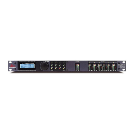
DriveRack 260. 0.1 Defining the 260 DriveRack System The dbx 260 DriveRack is the most effective way to manage all aspects of post mixer process- ing and signal routing. The 260 DriveRack essentially becomes the only device that you will need between the mixer and the power amps. -
Page 7: Service Contact Info
After expiration of the warranty, a reasonable charge will be made for parts, labor, and packing if you choose to use the factory service facility. In all cases, you are responsible for transportation charges to the factory. dbx will pay return shipping if the unit is still under war- ranty. -
Page 8: Warranty
In no event shall dbx or its dealers be liable for special or con- sequential damages or from any delay in the performance of this warranty due to causes beyond their control. - Page 9 Section 1 ™ DriveRack Getting Started ®...
-
Page 10: Section 1 - Getting Started
1.1 Rear Panel Connections IEC Power Cord Receptacle The DriveRack 260 comes with a power supply that will accept voltages ranging from 100V- 120V at frequencies from 50Hz-60Hz. An IEC cord is included. EU version accepts 220V-240V at frequencies from 50Hz-60Hz. - Page 11 Getting Started LCD Display The backlit LCD display of the DriveRack 260 provides the user with all of the vital processing information of the DriveRack 260 including: signal routing, effect block editing and Wizard Setup functions. The display will also notify the user if any internal clipping is taking place within the unit by displaying “CLIP”...
-
Page 12: Quick Start
Once all of the connections have been made and the unit is powered up, you can navigate through the entire signal path of the DriveRack 260 from the front panel of the unit. The display provides you with a clear and concise overview of each aspect ®... - Page 13 The features of the front panel of the DriveRack 260 are as follows from left to right. LCD Display- All operational information of the 260 DriveRack is displayed here. The display will also notify the user if any internal clipping is taking place within the unit.
- Page 14 ™ DriveRack Section 1 Getting Started System Setup • The arrow will indicate the selected Wizard setup. To select any one of the three options, rotate the <DATA> wheel. If you are performing the System setup, press either the <NEXT PG>...
- Page 15 ™ DriveRack Section 1 Getting Started Sub Speaker Select Sub PA >None • Rotate the <Data> wheel to select any one of the numerous custom-tuned SUB speaker options available. Once you have selected your SUB speaker option, press the <NEXT PG> button and the display will appear as fol- lows: High Amplifier Select an amplifier...
- Page 16 The Auto EQ Wizard automatically adjusts the response of the system by producing pink noise and adjusting the Graphic EQ until the RTA matches a selected response. From the 260 DriveRack Wizard menu, rotate the <DATA> wheel until the display appears as follows: DriveRack 260 Wizard System Setup Auto EQ Wizard AFS WIZARD •...
- Page 17 Because the fixed mode is sensitive, it is important not to present an external music source such as CD player or other audio signal into the system. From the Wizard menu, rotate the <DATA> wheel until the display appears as follows: DriveRack 260 Wizard System Setup Auto EQ Wizard AFS Wizard •...
- Page 18 ™ DriveRack Section 1 Getting Started ton and the display will read: F F F F F F L L L L L L Select total number of AFS filters. • You will now use the <DATA> wheel to select the number of fixed filters. This will range from values 0-12.
- Page 19 ™ DriveRack Section 1 Getting Started F F F F F F L L L L L L Slowly Increase the mixer gain to desired level. • You are now prompted to raise the output gain of the mixer to the level of the per- formance.
- Page 20 ™ DriveRack Section 1 Getting Started ®...
-
Page 21: Section 2 - Editing Functions
Section 2 ™ DriveRack Editing Functions EDITING FUNCTIONS ®... -
Page 22: Basic Navigation Modes
™ DriveRack Section 2 Editing Functions Editing Functions 2.1 Basic Navigation Modes Navigational aspects of the 260 DriveRack is simple and as follows. 1. FX buttons - This array of 12 FX buttons is your primary mode of directly accessing any effect module. 2. NEXTPG &... -
Page 23: Navigating The Pre-Eq Section
™ DriveRack Section 2 Editing Functions STORE(Delete) - The store button is used to store program edits.When pressed and held, the 260 will enter the PROGRAM DELETE module. RTA (Wizard) - This enters the RTA mode, or when held, enters the 260 DriveRack Wizard setup menu which includes: System Setup, Auto EQ setup and AFS Wizard. -
Page 24: Navigating The Other Section
™ DriveRack Section 2 Editing Functions 2.5 Navigating the Other Section From program mode, press the Other button. Successive presses of the Other button will move you to each of the various insert modules available. Pressing the Data Wheel will select the effect parameter to be edited. OTHER <PREV PG NEXT PG>... -
Page 25: Navigating The Delay Section
™ DriveRack Section 2 Editing Functions 2.7 Navigating the Delay Section From program mode, press the Delay button. Pressing the Data Wheel will select the effect parameter to be edited. Successive Presses of the Delay button will move you through pre and post crossover delays. DELAY DELAY Delay - On/Off... -
Page 26: Navigating The Wizard Section
™ DriveRack Section 2 Editing Functions 2.9 Navigating the Wizard Section From program mode, press the RTA/WIZARD button. Pressing the Data Wheel will select the effect parameter to be edited. WIZARD <PREV PG NEXT PG> SYSTEM SETUP GEQ Setup-Dual Mono Sub Speaker Select- Insert 1 Setup- Insert 2 Setup-... - Page 27 Section 3 ™ DriveRack SOFTWARE CONFIGURATION FUNCTIONS ®...
-
Page 28: Program Definition
™ DriveRack Section 3 Configuring the DriveRack™ The Configuring section of the 260 DriveRack will be your key to successful navigation of the configuration functions of the DriveRack. The following information provides, descriptions about program functions and in depth configuration options of the 260 DriveRack. 3.1 Program Definition The first step in understanding the programming capabilities of the DriveRack is to understand the components of a complete “program.”... -
Page 29: Editing Factory Programs
™ DriveRack Section 3 Configuring the DriveRack™ Navigation Modes Once you have selected a program with a configuration that accommodates your application, the DriveRack offers instant access to edit effect types within the configuration. To instantly access an effect module, simply press the corresponding button in the button array for the desired module. -
Page 30: Saving Factory Program Changes
™ DriveRack Section 3 Configuring the DriveRack™ 3.4 Saving Factory Programs Changes Once you are satisfied with the changes that have been made to a factory or user program, the DriveRack allows you to save these changes to the program as a custom USER program by pressing the STORE button. -
Page 31: Creating A User Configuration
™ DriveRack Section 3 Configuring the DriveRack™ 3.5 Creating a User Configuration User Configuration is an ideal feature available in the 260 DriveRack. Even with the versatility of the Factory configurations within the DriveRack, there may be an application that requires a unique “custom”... - Page 32 ™ DriveRack Section 3 Configuring the DriveRack™ B modules. Note that the same EQ types must be selected to link. Use the PREV PG and NEXT PG buttons to move through A and B, and then to the next module screen which will appear something like this: COMP Select...
- Page 33 ™ DriveRack Section 3 Configuring the DriveRack™ POST EQ Link/Unlink • You are now in the Post-Crossover EQ module. The arrow indicates that EQ type is selected. Rotate the DATA wheel to select the Parametric EQ type. Use the PREV PG and NEXT PG buttons to move through outputs 1-6, and then to the next mod- ule screen which will appear something like this: LIMITER...
-
Page 34: Saving Configuration Changes
™ DriveRack Section 3 Configuring the DriveRack™ NAME: Output Ch2 <DATA> - SELECT CHARACTER <PREV/NEXTPG> - LEFT/RIGHT <STORE>-EDIT/<UTIL>-EXIT • Once all of the naming assignments have been made, press the UTILITY button to return to Configuration mode. If all Configuration modifications you can press the PROGRAM button to return to program mode where you will proceed to Store your new USER configuration. - Page 35 Section 4 ™ DriveRack PARAMETERS DETAILED PARAMETERS ®...
-
Page 36: Section 4 - Detailed Parameters
™ DriveRack Section 4 Section 4 Detailed Parameters The 260DriveRack offers complete editing flexibility, by offering in-depth control over every parameter within each effect module. The following section will provide you with descriptions and explanations of all parameters within the 260 DriveRack. 4.1 Pre-Crossover EQ The 260 DriveRack’s Pre-Crossover EQ section may be configured as a single or linkable 28 band graphic EQ or 9-Band PEQ. -
Page 37: Feedback Eliminator (Afs)
™ DriveRack Section 4 Detailed Parameters Slope 9 3-12dB/Octave Sets the slope of the high shelf parametric EQ. Level 9 -12 to 12 dB Sets the overall gain of the high shelf parametric 4.2 Feedback Eliminator The 260 DriveRack offers the exclusive patent pending AFS (Advanced Feedback Suppression) feedback elimination module. -
Page 38: Subharmonic Synthesizer
™ DriveRack Section 4 Section 4 Detailed Parameters is replaced where a new feedback is detected and notched out. This mode is useful because feedback frequencies may change as the microphone is moved, and/or as the characteristics of the venue change. Note- Only the fixed filter settings will be stored with the new program. Type - Speech, Low Music, Medium Music and High Music If Fixed or Live mode is chosen, the text will read “Type.”... -
Page 39: Noise Gate
™ DriveRack Section 4 Detailed Parameters 24-36Hz and 36-56Hz (Subharmonic Synthesis) Level - 0 to 100% These controls individually let you customize the amount of the respective synthesized fre- quencies to be added in, tuning the ultimate bass response of your system to taste. For example, if the sound is too woofy or growly, try turning down the 36Hz-56Hz level. -
Page 40: Automatic Gain Control (Agc)
™ DriveRack Section 4 Section 4 Detailed Parameters 4.5 Automatic Gain Control (AGC) The AGC is used to keep the average level of a signal at a constant level. This is done by selecting a desired Target output level and Window. The AGC keeps the signal within the Window about the selected Target by slowly adjusting the gain. -
Page 41: Notch Filters
™ DriveRack Section 4 Detailed Parameters 4.6 Notch Filters The notch filter is the perfect tool for dropping out undesirable frequencies that may appear in the input signal. Up to six Notch filters are available for all six outputs. Notch On/Off Turns the notch filters on and off. -
Page 42: Compressor/Limiter
™ DriveRack Section 4 Section 4 Detailed Parameters Flatten/Restore This parameter either flattens the PEQ or restores the PEQ to its original shape. Type This parameter selects the PEQ type. Types include: 1. Bell-All parametrics are bell-shaped 2. HShelf - One shelf is High, while all others are bell 3. LShelf - One shelf is Low, while all oth- ers are bell and 4. - Page 43 ™ DriveRack Section 4 Detailed Parameters Threshold (T) -40 to +20dBu Threshold is the signal level at which the unit starts to compress the signal. If the level is set to -10 dBu, than any signal larger than -10 dBu is compressed while any signal that has a level that is lower than -10dBu is left at the same signal level.
- Page 44 ™ DriveRack Section 4 Section 4 Detailed Parameters OverEasy (O) Off to 10 There are ten levels of OverEasy® that can be used for the limiters. The point when the com- pressor starts to compress is the "knee." When the compressor starts to reduce the level of a signal abruptly as it passes over the threshold this is called "hard knee"...
-
Page 45: Alignment Delay
™ DriveRack Section 4 Detailed Parameters reduction needed to keep the output signal below the ceiling set by the Instantaneous Transient Clamp™. Note that since the PeakStop+™ limiter is a fail-safe limiter, it must come after the OUTPUT GAIN control. Overshoot 1-6 This parameter sets the amount of overshoot for the Instantaneous Transient Clamp™. -
Page 46: Output
™ DriveRack Section 4 Detailed Parameters Noise Level -10 to 10 (Mixer and Router) Adjusts the overall level of the pink noise generator. 4.12 Output The output section 480, 481 and 482 DriveRack™ units provide the user with the ability to con- trol output levels of the unit and adjust phase compensation of loudspeakers within the signal path. - Page 47 Section 5 ™ DriveRack Utilities/Meters UTILITIES/ METERS SECTION ®...
-
Page 48: Section 5 - Utilities/Meters
™ DriveRack Section 5 Utilities/Meters The Utility section of the 260 DriveRack gives you the ability to perform several key operational functions to the DriveRack including: Security settings, Power-up features, Program list organi- zation, Auto EQ plotting, adjustment of Output Jumper settings and Display contrast settings. Additionally, pressing and holding the utility button will allow you to enter the metering sec- tion of the 260. -
Page 49: Zc Setup
To exit, press the PROGRAM/CONFIG button. 5.1.3 -Page 3 - ZC Setup A unique feature of the 260 DriveRack is its ability to interface with dbx proprietary Zone Controller wall-panel switches. This feature gives you the ability to control various parameters of the 260 such as Boost and Cut Program Changes and Switch closure changes. -
Page 50: Security
™ DriveRack Section 5 Utilities/Meters Panel 1 ZC-2 Boost 0dB Cut Output • Pressing the DATA wheel will give you the option of selecting the range of the boost and the cut of the potentiometer on the ZC-2 or ZC-2. Once the boost and cut range has been selected, pressing (select) and rotating the DATA wheel will let you select any one of the six outputs to be affected by the boost and cut control. - Page 51 ™ DriveRack Section 5 Utilities/Meters different levels of access, this ensures limited access to different users. This security system also allows you to create unique passwords which will limit/prevent any other users from access to the system. The following infor- mation is provided to help you set all security parameters.
- Page 52 ™ DriveRack Section 5 Utilities/Meters Password Edit High Password Edit Med Password Press Store to Change • Press the DATA wheel to select password to edit. When the level password has been selected, press the store button to select a name. The display will appear as follows: NAME: ROCK VENUE <DATA>...
-
Page 53: Program List/Program Change
™ DriveRack Section 5 Utilities/Meters • Once you have entered your security password, press the STORE button to store the password and the clearance level will be changed. To abort this procedure at any time, press PROGRAM/CONFIG button. • Press the PROGRAM/CONFIG button to return to normal operation. •... -
Page 54: Output Jumper Switches
™ DriveRack Section 5 Utilities/Meters • To set the program number that will correspond with the index number, press the DATA wheel. once this is selected, rotate the DATA wheel to select the desired program number. • Once your program list has been built, press the PROGRAM/CONFIG button to exit. Program lock means that program numbers below the selected number cannot be overwrit- ten. -
Page 55: Meters
™ DriveRack Section 5 Utilities/Meters 5.2.1 - Meters To meter various aspects of the 260, press and hold the UTILITY button until the display enters the Metering section. • Use the PREV PG and NEXT PG button to move to the page that appears as follows: INS COMP o+ -30-20 0 +20... - Page 56 ™ DriveRack Section 5 Utilities/Meters • Use the PREV PG and NEXT PG button to move to the page that appears as follows: Output Trims Trim 0.0 Net 0.0 dB Trim 0.0 Net 0.0 dB Trim 0.0 Net 0.0 dB This (as well as the following) page show the amount of Trim and Net Reduction within the output section.
-
Page 57: Section 6 - Remote Control
Section 6 ™ DriveRack Remote Control DriveWare ™ ZC-Remote Zone Controllers ®... -
Page 58: Pc Gui Installation
RS232 COMM port must be turned off. INSTALL • Install the DriveRack™ GUI interface from either the dbx Professional Products website at: www.dbxpro.com or from the CD ROM onto your your PC or laptop. • Once the software is downloaded or CD is loaded, double click on the file named: DriveRack™... - Page 59 ™ DriveRack SECTION 6 Remote Control The utility menus will appear as follows: • To customize the mode of operation to best suit your needs, it is recommended that at this point, you set your desired preferences in the preference folder, which can be accessed in the file menu and will appear as follows: ®...
-
Page 60: Cable Specs
™ DriveRack SECTION 6 Remote Control Note: The Baud rate must be set to 38400. GUI Recommended Cable Specifications: PC GUI Interface - DB-9 female-to-female nul modem cable. (10 feet) ® DriveRack™ User Manual... -
Page 61: Zc-Zone Controllers
™ DriveRack SECTION 6 Remote Control 6.2.1 ZC-Zone Controllers Zone Controller Installation The installation of the Zone Controllers MUST be accomplished with the use of cable which is rated VW-1 or higher. Common NEC designations which meet this rating include: CMP, CMR, CMG, CM and CMX. - Page 62 ™ DriveRack SECTION 6 Remote Control ® DriveRack™ User Manual...
- Page 63 Remote Control Zone Controller Wiring The DriveRack 260 Zone Controllers, (ZC-1, ZC-2, ZC-3, ZC-4) can be wired serially or in par- allel. To wire in series each Zone Controller must have an identification or zone number cho- sen using the DIP switches on the side of the controller (see diagram A). Each controller must have a unique number chosen although there may be multiple Zone Controllers controlling a single zone, or a single Zone Controller that controls multiple outputs.
-
Page 64: Remote Control
™ DriveRack SECTION 6 Remote Control Diagram C Cable Specification: Cat 5 Cable - 4-Twisted Pairs of 24 AWG wire RJ-45 RJ-45 (8-Position) (8-Position) White/Orange -VREF Orange -Zone 1 White/Green -Zone 2 Green -Zone 3 White/Blue -Zone 4 Blue -Zone 5 White/Brown -Zone 6 Brown... - Page 65 Cable runs of up to 1,000 feet may be achieved using “Home Run” wiring. An example of this is shown in Diagram C. A dbx Zone Controller Break Out Box (dbx ZC-BOB) is used to parallel several cable runs. It should be noted that a 1,000 foot cable with a single Zone Controller may be connected directly to the DriveRack 260.
-
Page 67: Section 7 - Application Guide
Section 7 ™ DriveRack APPLICATION GUIDE ®... -
Page 68: Stereo W/ 4 Aux Zones
4. Using the Utility Menu, select the ID for each ZC-1 and ZC-2 Zone Controller and program its output level boost and cut parameters. Left Right JBL AE Series AC2215/64 dbx ZC-1 dbx ZC-2 JBL Control 26C JBL Control 26C Ceiling Speaker Ceiling Speaker... -
Page 69: Stereo Tri-Amp
™ DriveRack Section 7 Application Guide 7.2- Stereo Tri-amp Hardware Connect the outputs from the mixer to the inputs of the DriveRack™. 2. Connect the outputs of the DriveRack™ and run to the selected speaker amplifier. 3. Making sure that all outputs are muted, apply power to the mixer and amplifiers. Software 1. - Page 70 6. Using the Utility Menu, select the ID for the ZC-3 Zone Controller and select the programs that the ZC-3 will load from each of its positions. Left Right dbx ZC-3 MA-5002VZ dbx ZC-1 dbx ZC-2 dbx ZC-1...
-
Page 71: Stereo Bi-Amp W/ Dual Delays
3. Adjust the individual parameters for the system by pressing the Processing Module buttons. 4. Using the Utility Menu, select the ID for each ZC-1 and ZC-2 Zone Controller and program its output level boost and cut parameters. Left Right dbx ZC-2 MA-5002VZ JBL Control 25 Zone A JBL AE Series... - Page 72 ™ DriveRack Section 7 Application Guide ® DriveRack™ User Manual...
-
Page 73: Appendix
Appendix ™ DriveRack ®... -
Page 74: Factory Reset
All Power-Up Functions require a button(s) to be pressed and held as the unit power is turned on. DriveRack 260 Power-Up Button Functions Factory (“Hard”) Reset. Press and hold the <STORE> button at power-up until the following message appears: “! HARD RESET?”... -
Page 75: Specifications
Alignment Delay: 10ms per channel (60ms total) A/D Performance: Type: dbx Type IV conversion system Dynamic Range: >107 dB unweighted, >110 dB A-weighted Type IV dynamic range: 123 dB with transient material, A-weighted, 22kHz BW 121 dB with transient material, unweighted, 22kHz BW 115... -
Page 76: Auto Eq Optimization
™ DriveRack Appendix A A.4 Auto EQ Optimization Tips By using the setup wizard, cross over output gains and post cross over parametric EQ settings are set to match your system. The Auto-EQ can be used to adjust your system to compensate for room effects, and adjust the response of the entire system to your liking. -
Page 77: Crossover Diagrams
™ DriveRack Appendix A A.5 Crossover Diagrams 1X1(1-band) 1X4(4-band) 1X2(2-band) 1X3(3-band) 1X6(4-band) 1X5(4-band) 2X3(2-band) L Mono 2X5 (3-band) 2X4(2-band) 2X6 (3-band) L Mono ® DriveRack™ User Manual... -
Page 78: Input And Output Section Diagrams
™ DriveRack Appendix A A.6 Program List/ Speaker Tunings/ Power Amp Tunings Factory Program List AM4212/64 SR4718X AM4212/00 SR4719X 1. 2x3w/3Zones AC2212/95 MP418S 2. LCRw/Cluster AC2212/64 MP418SP 3. 1x4w/2Zones AC2212/00 MP255S 4. 2x5w/1Zone SR4702X EONSUBG2 5. 2x4Tri-Amped SR4722X SF22SP 6. 2x4w/2Zones SR4725X FR250Z 7. -
Page 79: Block Diagram
™ DriveRack Appendix A A.7 Block Diagram ® DriveRack™ User Manual... - Page 80 ™ DriveRack Appendix A A.8 Input and Output Diagrams XLR 1 Input 1 Gain DSP Input 1 Input 2 Gain Input 1 Gain XLR 2 DSP Input 2 Input 2 Gain Euroblock ® DriveRack™ User Manual...
-
Page 81: Gain Level Jumpers
In the DriveRack 260 we have included a Wizard setup tool to help in system setup. If you use the Wizard to set up your DriveRack 260 it will auto- matically set the limiters for some amplifier selections. If your amplifiers are not available in the Wizard, you should choose the Custom setting. - Page 82 You can now use the output limiters in the DriveRack 260 to protect the amplifier from clipping no matter what you do at the con- sole. With the amplifiers clipping, now go to the Limiter page of the DriveRack 260 and turn the limiter for each output band on.
- Page 83 ® 8760 South Sandy Parkway • Sandy, Utah 84070 Phone: (801) 568-7660 • Fax (801) 568-7662 Int’l Fax: (801) 568-7583 Questions or comments? E-mail us at: customer@dbxpro.com or visit our World Wide Web home page at: www.dbxpro.com or www.driverack.com A Harman International Company 18-1796-A...