Cisco 2811 - Voice Security Bundle Router Hardware Manual
Introduction and warnings
Hide thumbs
Also See for 2811 - Voice Security Bundle Router:
- Manual (111 pages) ,
- Quick start manual (45 pages) ,
- Operations (31 pages)
Table of Contents
Advertisement
Quick Links
Cisco 2800 Series Hardware Documents:
Introduction and Warnings
This introduction discusses the objectives, audience, organization, and conventions of these hardware
documents, and points to related documents that have information beyond the scope of these documents.
This preface contains the following sections:
•
•
•
•
•
•
•
•
•
•
•
Objectives
These hardware documents provide you with comprehensive hardware-related information about
Cisco 2800 series integrated services routers, including platform descriptions, safety information, site
preparation, chassis installation and interconnection, power up, initial configuration, troubleshooting,
interface card and module installation, and procedures for maintenance and upgrades.
These documents provide enough initial software configuration information to establish network
communication. For detailed software configuration information, refer to the Cisco 2800 series software
configuration documents and to the Cisco IOS configuration guides and command reference
publications. These publications are available online. See the
page 11
Corporate Headquarters:
Cisco Systems, Inc., 170 West Tasman Drive, San Jose, CA 95134-1706 USA
Copyright © 2004 Cisco Systems, Inc. All rights reserved.
Objectives, page 1
Audience, page 2
Conventions, page 3
Safety Warnings, page 4
Related Documentation, page 9
Obtaining Documentation, page 11
Documentation Feedback, page 12
Obtaining Technical Assistance, page 12
for more information.
"Obtaining Documentation" section on
Advertisement
Chapters
Table of Contents

Related Manuals for Cisco 2811 - Voice Security Bundle Router


Summary of Contents for Cisco 2811 - Voice Security Bundle Router
-
Page 1: Table Of Contents
These documents provide enough initial software configuration information to establish network communication. For detailed software configuration information, refer to the Cisco 2800 series software configuration documents and to the Cisco IOS configuration guides and command reference publications. -
Page 2: Audience
Provides information about cables needed to install your Cisco 2800 Series Routers Cisco 2800 series router. Chassis Installation Procedures for Describes how to install your Cisco 2800 series router on a Cisco 2800 Series Routers desktop, in a rack, or on a wall. Cable Connection Procedures for... -
Page 3: Conventions
Conventions Table 1 Hardware Documentation for Cisco 2800 Series Routers (Continued) Topic Description Installing and Upgrading Internal Describes how to install or upgrade modules that are Modules in Cisco 2800 Series Routers located internally within the router, such as memory modules, AIMs, PVDMs, and power supplies. -
Page 4: Safety Warnings
Safety warnings appear throughout these publications in procedures that, if performed incorrectly, may harm you. A warning symbol precedes each warning statement. To see translations of the warnings that appear in these publications, refer to the Cisco 2800 Series Routers Regulatory Compliance and Safety Information document that accompanied your router. - Page 5 Vea las traducciones de las advertencias que acompañan a este dispositivo. Nota GUARDE ESTAS INSTRUCCIONES Cisco 2800 Series Hardware Documents: Introduction and Warnings OL-5808-01...
- Page 6 Se översättningarna av de varningsmeddelanden som finns i denna publikation, och se de översatta säkerhetsvarningarna som medföljer denna anordning. OBS! SPARA DESSA ANVISNINGAR Cisco 2800 Series Hardware Documents: Introduction and Warnings OL-5808-01...
- Page 7 Brug erklæringsnummeret efter hver advarsel for at finde oversættelsen i de oversatte advarsler, der fulgte med denne enhed. GEM DISSE ANVISNINGER Cisco 2800 Series Hardware Documents: Introduction and Warnings OL-5808-01...
- Page 8 Safety Warnings Cisco 2800 Series Hardware Documents: Introduction and Warnings OL-5808-01...
-
Page 9: Related Documentation
Related Documentation Related Documentation The Cisco IOS software running your Cisco 2800 series router includes extensive features and functionality. For information that is beyond the scope of these documents, or for additional information, use the following resources: Make sure that you have access to the documents listed in Table 3. -
Page 10: Cisco 90-Day Limited Hardware Warranty Terms
Your formal Warranty Statement, including the warranties and license agreements applicable to Cisco software, is available on Cisco.com. Follow these steps to access and download the Cisco Information Packet and your warranty and license agreements from Cisco.com. -
Page 11: Obtaining Documentation
Ninety (90) days. Replacement, Repair, or Refund Policy for Hardware Cisco or its service center will use commercially reasonable efforts to ship a replacement part within ten (10) working days after receipt of a Return Materials Authorization (RMA) request. Actual delivery times can vary, depending on the customer location. -
Page 12: Ordering Documentation
Technical Support provides 24-hour-a-day, award-winning technical assistance. The Cisco Technical Support Website on Cisco.com features extensive online support resources. In addition, Cisco Technical Assistance Center (TAC) engineers provide telephone support. If you do not hold a valid Cisco service contract, contact your reseller. -
Page 13: Cisco Technical Support Website
URL: http://www.cisco.com/techsupport/servicerequest For S1 or S2 service requests or if you do not have Internet access, contact the Cisco TAC by telephone. (S1 or S2 service requests are those in which your production network is down or severely degraded.) Cisco TAC engineers are assigned immediately to S1 and S2 service requests to help keep your business operations running smoothly. -
Page 14: Obtaining Additional Publications And Information
• Cisco Marketplace, the company store, at this URL: http://www.cisco.com/go/marketplace/ The Cisco Product Catalog describes the networking products offered by Cisco Systems, as well as • ordering and customer support services. Access the Cisco Product Catalog at this URL: http://cisco.com/univercd/cc/td/doc/pcat/ Cisco Press publishes a wide range of general networking, training and certification titles. - Page 15 Obtaining Additional Publications and Information Cisco 2800 Series Hardware Documents: Introduction and Warnings OL-5808-01...
- Page 16 Obtaining Additional Publications and Information CCVP, the Cisco Logo, and the Cisco Square Bridge logo are trademarks of Cisco Systems, Inc.; Changing the Way We Work, Live, Play, and Learn is a service mark of Cisco Systems, Inc.; and Access Registrar, Aironet, BPX, Catalyst, CCDA, CCDP, CCIE, CCIP, CCNA, CCNP, CCSP, Cisco, the Cisco...
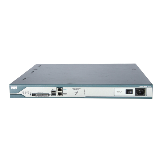
- Page 17 The Cisco 2800 series consists of four versions. The Cisco 2801 routers and Cisco 2811 routers are one rack unit in height and have two 10/100 LAN ports. The more powerful Cisco 2821 routers and Cisco 2851 routers are two rack units in height and have two 10/100/1000 LAN ports.
-
Page 18: Hardware Features
LED indicators, chassis ventilation, and the internal clock. Product Serial Number Location The serial number label for Cisco 2801 routers is located on the rear of the chassis, along the bottom edge near the lower left corner. (See... - Page 19 The serial number for Cisco 2801 routers is 11 characters long. Note The serial number label for Cisco 2811 routers is located on the rear of the chassis, near the top right corner, to the left of the CLEI label. (See...
- Page 20 Hardware Features The serial number label for Cisco 2821 and Cisco 2851 routers is located on the rear of the chassis, near the top right corner, below the CLEI label. (See Figure Figure 6 Serial Number Location on the Cisco 2821 and Cisco 2851 Routers...
-
Page 21: Removable And Interchangeable Modules
The network modules, extension voice modules, and interface cards fit into slots, located on the front of the chassis on the Cisco 2801 router, and on the rear of the chassis on the Cisco 2811, Cisco 2821, and Cisco 2851 routers; they can be removed and installed without opening the chassis. - Page 22 Default memory—256 MB Maximum memory—1024 MB 1. Cisco 2801 routers have 128 MB of SDRAM soldered onto the system board. You can install a DIMM into the expansion slot to increase memory to the maximum of 384 MB. 2. Cisco 2811 routers can accept two 256 MB DIMMs to provide 768 MB of usable memory.
-
Page 23: Led Indicators
Cisco 2800 series routers. Cisco 2801 routers are equipped for operation using AC power only. Cisco 2811, Cisco 2821, and Cisco 2851 routers can be equipped for operation using either AC or DC input power by installation of the appropriate chassis power supply. IP phone power is supported if the appropriate AC-input chassis power supply is installed. - Page 24 For LED troubleshooting information, including possible trouble causes and corrective actions, see Table 1 in the “Troubleshooting Cisco 2800 Series Routers” document. Table 5 Summary of Cisco 2801 Series LED Indicators Color Description Location SYS PWR Green Router has successfully booted up and the Front software is functional.
- Page 25 FE or GE port operating at 10 Mbps 2 blinks + pause FE or GE port operating at 100 Mbps 3 blinks + pause GE port operating at 1000 Mbps (Cisco 2821 and Cisco 2851 only) L (= Link) Green...
-
Page 26: Chassis Ventilation
The Cisco 2801 router has a socketed lithium battery. This battery lasts the life of the router under the operating environmental conditions specified for the router, and is not field-replaceable. If the lithium battery in a Cisco 2801 router should fail, the router must be returned to Cisco for repair. Note... - Page 27 Chassis Views Figure 7 Front Panel of the Cisco 2801 Router 11 12 Slot 0 (VIC or VWIC, for voice only) Auxiliary Power (AUX/PWR) LED Slot 1 (WIC, VIC, VWIC, or HWIC) Universal serial bus (USB) port Slot 2 (WIC, VIC, or VWIC)
- Page 28 Cisco 2811 router. Figure 12 shows the rear panel of a Cisco 2811 router. Figure 9 Front Panel of Cisco 2811 Router with AC Input Power and Without IP Phone Power Output OPTIONAL RPS INPUT CONSOLE AUX/ 100-240 V~ 2A...
- Page 29 High-speed WAN interface card slot 3 High-speed WAN interface card slot 0 Network module enhanced (NME) slot 1. The network module slot is compatible with Cisco network modules of type NM (network module) and NME (network module enhanced). Overview of Cisco 2800 Series Routers OL-5783-01...
- Page 30 Figure 17 shows the rear panel of a Cisco 2851 router. Figure 13 Front Panel of Cisco 2821 and Cisco 2851 Routers with AC Input Power and Without IP Phone Power Output CONSOLE AUX/ COMPACT FLASH Do Not Remove During Network Operation...
- Page 31 Screw holes for ground lug High-speed WAN interface card slot 2 1. The network module slot is compatible with Cisco network modules of type NM (network module), NME (network module enhanced), and NME-X (enhanced extended). Overview of Cisco 2800 Series Routers...
-
Page 32: Interface Numbering
Screw holes for ground lug High-speed WAN interface card slot 2 1. The network module slot is compatible with Cisco network modules of type NM (network module), NME (network module enhanced), NME-X (enhanced extended), NMD (double-wide), and NME-XD (enhanced extended double-wide). - Page 33 1. A VWIC in slots 1, 2, and 3 can operate in both data and voice mode; in slot 0, a VWIC can operate only in voice mode. On the Cisco 2801 router, the numbering format for configuring an asynchronous interface is 0/slot/port. Note To configure the line associated with an asynchronous interface, simply use the interface number to specify the async line.
-
Page 34: Specifications
3. Interface card slot numbers for double-width (HWIC-D) slots are 1 and 3 only. 4. Specify the line number in the Cisco IOS CLI by using the interface number for the associated asynchronous serial interface. 5. “1” is the network module slot number in all Cisco 2800 series routers. - Page 35 53 dBA for temperatures above 116° F (47° F) Safety compliance UL 60950; CAN/CSA C22.2 No. 60950-00; IEC 60950; EN 60950-1; AS/NZS 60950 For detailed compliance information, refer to the Cisco 2800 and Cisco 3800 Series Integrated Services Routers Regulatory Compliance and Safety Information document. Immunity compliance EN300386;...
- Page 36 57 dBA in maximum ambient temperature Safety compliance UL 60950; CAN/CSA C22.2 No. 60950-00; IEC 60950; EN 60950-1; AS/NZS 60950 For detailed compliance information, refer to the Cisco 2800 and Cisco 3800 Series Integrated Services Routers Regulatory Compliance and Safety Information document. Immunity compliance EN300386;...
- Page 37 FCC Part 15; ICES-003 Class A; EN55022 Class A; CISPR22 Class A; AS/NZS 3548 Class A; VCCI Class A; EN 300386; EN61000-3-3; EN61000-3-2 For detailed compliance information, refer to the Cisco 2800 and Cisco 3800 Series Integrated Services Routers Regulatory Compliance and Safety Information document.
- Page 38 52 dBA in maximum ambient temperature Safety compliance UL 60950; CAN/CSA C22.2 No. 60950-00; IEC 60950; EN 60950-1; AS/NZS 60950 For detailed compliance information, refer to the Cisco 2800 and Cisco 3800 Series Integrated Services Routers Regulatory Compliance and Safety Information document. Immunity compliance EN300386;...
- Page 39 FCC Part 15; ICES-003 Class A; EN55022 Class A; CISPR22 Class A; AS/NZS 3548 Class A; VCCI Class A; EN 300386; EN61000-3-3; EN61000-3-2 For detailed compliance information, refer to the Cisco 2800 and Cisco 3800 Series Integrated Services Routers Regulatory Compliance and Safety Information document.
- Page 40 52 dBA in maximum ambient temperature Safety compliance UL 60950; CAN/CSA C22.2 No. 60950-00; IEC 60950; EN 60950-1; AS/NZS 60950 For detailed compliance information, refer to the Cisco 2800 and Cisco 3800 Series Integrated Services Routers Regulatory Compliance and Safety Information document. Immunity compliance EN300386;...
-
Page 41: Regulatory Compliance
Cisco 3800 Series Integrated Services Routers Regulatory Compliance and Safety Information document. Regulatory Compliance For compliance information, refer to the Cisco 2800 and Cisco 3800 Series Integrated Services Routers Regulatory Compliance and Safety Information document that accompanied the router. Overview of Cisco 2800 Series Routers... - Page 42 Regulatory Compliance CCVP, the Cisco Logo, and the Cisco Square Bridge logo are trademarks of Cisco Systems, Inc.; Changing the Way We Work, Live, Play, and Learn is a service mark of Cisco Systems, Inc.; and Access Registrar, Aironet, BPX, Catalyst, CCDA, CCDP, CCIE, CCIP, CCNA, CCNP, CCSP, Cisco, the Cisco...
-
Page 43: Safety Recommendations
Preinstallation Requirements and Planning for Cisco 2800 Series Routers This document describes site requirements and equipment needed to install your Cisco 2800 series integrated services router. It includes the following sections: Safety Recommendations, page 1 • • General Site Requirements, page 3 Installation Checklist, page 6 •... -
Page 44: Safety With Electricity
Never install telephone jacks in wet locations unless the jack is specifically designed for it. • • Never touch uninsulated telephone wires or terminals unless the telephone line is disconnected at the network interface. • Use caution when installing or modifying telephone lines. Preinstallation Requirements and Planning for Cisco 2800 Series Routers OL-5784-01... -
Page 45: Preventing Electrostatic Discharge Damage
All units include a 6-foot (1.8-meter) electrical power cord. (A label near the power inlet indicates • the correct voltage, frequency [AC-powered systems only], current draw, and power dissipation for the unit.) Table 1 lists power requirements for Cisco 2800 series routers. Preinstallation Requirements and Planning for Cisco 2800 Series Routers OL-5784-01... -
Page 46: Site Environment
Site Environment Cisco 2800 series routers can be placed on a desktop or installed in a rack. This Cisco 2811 router can also be wall mounted. The location of your router and the layout of your equipment rack or wiring room are extremely important considerations for proper operation. -
Page 47: Site Configuration
Equipment Racks Cisco 2800 series routers include brackets for use with a 19-inch rack or, if specified in your order, optional larger brackets for use with a 23-inch rack. Brackets for a 23-inch rack are not available for Cisco 2801 routers. -
Page 48: Installation Checklist
Chassis components verified Initial electrical connections established ASCII terminal (for local configuration) or modem (for remote configuration) available Signal distance limits verified Startup sequence steps completed Initial operation verified Software image verified Preinstallation Requirements and Planning for Cisco 2800 Series Routers OL-5784-01... -
Page 49: Creating A Site Log
Rubber feet for desktop mounting (Cisco 2801 router only) • Rack-mount brackets with screws for 19-inch racks • Ground lug and two mounting screws (Cisco 2811, Cisco 2821, and Cisco 2851 routers only) • Cable management bracket • RJ-45-to-DB-9 console cable •... -
Page 50: Required Tools And Equipment For Installation And Maintenance
Data service unit (DSU) or channel service unit/data service unit (CSU/DSU) as appropriate for • serial interfaces. External CSU for any CT1/PRI modules without a built-in CSU. • NT1 device for ISDN BRI S/T interfaces (if not supplied by your service provider). • Preinstallation Requirements and Planning for Cisco 2800 Series Routers OL-5784-01... - Page 51 Required Tools and Equipment for Installation and Maintenance Preinstallation Requirements and Planning for Cisco 2800 Series Routers OL-5784-01...
- Page 52 Required Tools and Equipment for Installation and Maintenance CCVP, the Cisco Logo, and the Cisco Square Bridge logo are trademarks of Cisco Systems, Inc.; Changing the Way We Work, Live, Play, and Learn is a service mark of Cisco Systems, Inc.; and Access Registrar, Aironet, BPX, Catalyst, CCDA, CCDP, CCIE, CCIP, CCNA, CCNP, CCSP, Cisco, the Cisco...
-
Page 53: Console And Auxiliary Port Considerations
Port and Cable Information for Cisco 2800 Series Routers This document provides information about cables needed to install your Cisco 2800 series integrated services router. It includes the following sections: Console and Auxiliary Port Considerations, page 1 • • Preparing to Connect to a Network, page 2 Console and Auxiliary Port Considerations The router includes an asynchronous serial console port and an auxiliary port. -
Page 54: Auxiliary Port Connections
For connection to a modem, your router is provided with an RJ-45-to-DB-25 adapter cable. (A DB-9-to-DB-25 adapter is also included with the Cisco 2801 router.) For detailed information about connecting devices to the auxiliary port, see the “Connecting to a Console Terminal or Modem”... -
Page 55: Ethernet Connections
Preparing to Connect to a Network Ethernet Connections The IEEE has established Ethernet as standard IEEE 802.3. Cisco 2800 series routers support the following Ethernet implementations: 1000BASE-T—1000 Mbps full-duplex transmission over a Category 5 or better unshielded • twisted-pair (UTP) cable. Supports the Ethernet maximum length of 328 feet (100 meters). - Page 56 The synchronous serial ports available for the router support the following signaling standards: EIA/TIA-232, EIA/TIA-449, V.35, X.21, and EIA-530. You can order a Cisco DB-60 shielded serial transition cable that has the appropriate connector for the standard you specify. The documentation for the device you want to connect should indicate the standard used for that device.
-
Page 57: Isdn Bri Connections
Use a BRI cable (not included) to connect the BRI WAN interface card directly to an ISDN. Table 3 lists the specifications for ISDN BRI cables. Also, refer to the Cisco Modular Access Router Cable Specifications online document for pinouts. This document is located on Cisco.com. Port and Cable Information for Cisco 2800 Series Routers OL-5785-01... - Page 58 Cisco.com. CCVP, the Cisco Logo, and the Cisco Square Bridge logo are trademarks of Cisco Systems, Inc.; Changing the Way We Work, Live, Play, and Learn is a service mark of Cisco Systems, Inc.; and Access Registrar, Aironet, BPX, Catalyst, CCDA, CCDP, CCIE, CCIP, CCNA, CCNP, CCSP, Cisco, the Cisco...
-
Page 59: Series Routers
Chassis Installation Procedures for Cisco 2800 Series Routers This document describes how to install your Cisco 2800 series integrated services router on a desktop or in a rack. It includes the following sections: Installing Modules and Interface Cards, page 1 •... - Page 60 Cisco Network Modules Hardware Installation Guide • For HWICs and VICs: Installing Interface Cards in Cisco 2800 Series Routers • Quick Start Guide: Interface Cards for Cisco 1600, 1700, 2600, 3600, and 3700 Series ---and Cisco • 2800 Series Cisco Interface Cards Installation Guide •...
- Page 61 Screw holes for ground lug High-speed WAN interface card slot 2 1. The network module slot is compatible with Cisco network modules of type NM (network module), NME (network module enhanced), and NME-X (enhanced extended). Chassis Installation Procedures for Cisco 2800 Series Routers...
- Page 62 Screw holes for ground lug High-speed WAN interface card slot 2 1. The network module slot is compatible with Cisco network modules of type NM (network module), NME (network module enhanced), NME-X (enhanced extended), NMD (double-wide), and NME-XD (enhanced extended double-wide).
-
Page 63: Setting Up The Chassis
Statement 1 You can set any Cisco 2800 series router on a desktop or install it in a rack. A Cisco 2811 router can also be mounted on a wall or other flat surface. See the applicable instructions in the following sections. - Page 64 Setting Up the Chassis Cisco 2811, Cisco 2821, and Cisco 2851 routers can be installed in 19 (48.26-cm)- and 23-inch (58.42-cm) racks. Cisco 2801 routers can be installed only in 19-inch racks, and cannot be center mounted. Use the standard brackets shipped with the router for mounting the chassis in a 19-inch rack;...
- Page 65 Figure 8 Attaching Rack-Mounting Brackets to a Cisco 2801 Router Attaching Rack-Mount Brackets to Cisco 2811, Cisco 2821, and Cisco 2851 Routers Attach the mounting brackets to the router chassis as shown in Figure 9...
- Page 66 When the correct screw holes are used, the small threaded holes in the brackets line up with unused screw holes in the rack. If the small holes do not line up with the rack holes, you must raise or lower the brackets to the next rack hole. Chassis Installation Procedures for Cisco 2800 Series Routers OL-5786-03...
- Page 67 The optional cable management bracket provides attachment points for organizing and routing cables. On brackets for the Cisco 2801 and Cisco 2811 routers, attach the cable management bracket to the left or right rack-mount bracket using the screw provided, as shown in...
-
Page 68: Chassis Grounding
Setting the Chassis on a Desktop You can place Cisco 2800 series routers on a desktop or shelf. If you are placing a Cisco 2801 router on a desktop, you must first install the four rubber feet that are supplied in the accessory kit. They provide space for air circulation and antiskid protection. - Page 69 “Installing the Chassis Ground Connection” section on page Mounting a Cisco 2811 Router on a Wall This section explains how to mount Cisco 2811 routers on a wall or other vertical surface. Mounting Cisco 2801, Cisco 2821, and Cisco 2851 routers on a wall is not recommended.
- Page 70 After the router is installed, you must connect the chassis to a reliable earth ground. For the chassis ground connection procedures, see the “Installing the Chassis Ground Connection” section on page Chassis Installation Procedures for Cisco 2800 Series Routers OL-5786-03...
-
Page 71: Installing The Chassis Ground Connection
) copper wire and the ground lug provided in the accessory kit. Note NEBS-compliant grounding is not supported on the Cisco 2801 router. • For NEC-compliant grounding, use size 14 AWG (2 mm ) or larger copper wire and an appropriate user-supplied ring terminal with an inner diameter of 1/4 in. - Page 72 Installing the Chassis Ground Connection To install the ground connection for a Cisco 2800 series router, perform the following steps: Step 1 Strip one end of the ground wire to the length required for the ground lug or terminal. •...
- Page 73 Guide. CCVP, the Cisco Logo, and the Cisco Square Bridge logo are trademarks of Cisco Systems, Inc.; Changing the Way We Work, Live, Play, and Learn is a service mark of Cisco Systems, Inc.; and Access Registrar, Aironet, BPX, Catalyst, CCDA, CCDP, CCIE, CCIP, CCNA, CCNP, CCSP, Cisco, the Cisco...
- Page 74 Installing the Chassis Ground Connection Chassis Installation Procedures for Cisco 2800 Series Routers OL-5786-03...
- Page 75 Cable Connection Procedures for Cisco 2800 Series Routers This document describes how to connect your Cisco 2800 series integrated services router to a power source and to networks and external devices. It includes the following sections: Power Connections, page 2 •...
-
Page 76: Power Connections
Power Connections Power Connections This section explains how to connect AC or DC power to Cisco 2800 series routers. It covers the following topics: Connecting Routers to AC Power, page 2 • Connecting Routers to DC Power, page 2 •... -
Page 77: Dc Wiring Requirements
“Connecting Routers to Backup Power” section on page DC Wiring Requirements A Cisco 2811, Cisco 2821, or Cisco 2851 router with a DC-input power supply requires copper wire and crimp-type terminals for the power connections. Table 1... - Page 78 DC-input power source wire extends from the terminal block plug. Statement 122 Do not overtorque the terminal block contact screws. Recommended torque is 8.0 ± 0.5 in-lb Caution (0.90 ± 0.05 N-m). Cable Connection Procedures for Cisco 2800 Series Routers OL-5787-02...
- Page 79 Power Connections Figure 1 DC Power Connections for Cisco 2800 Series Routers -DC, input A Return, input A Return, input A +DC, input A Safety ground Safety ground Return, input B +DC, input B -DC, input B Return, input B...
- Page 80 Plastic covers Approved Scenarios and Scenarios Not Approved for Dual DC Power Supply Configuration in Cisco 2800 Routers You can connect a single DC power source to either the A input or the B input. If there are dual power sources, connect one source to the A input and one source to the B input.
- Page 81 When source A and source B are wired with common negative terminals, as in Figure 5, discharging does not occur and there is no restriction requiring that source A and source B voltages be equal. Cable Connection Procedures for Cisco 2800 Series Routers OL-5787-02...
- Page 82 7, source A and source B are wired with opposite polarity grounds. Do not use this configuration. Caution Do not use the DC input configuration shown in Figure Figure 7 Source A and Source B Wired with Opposite-Polarity Grounds Cable Connection Procedures for Cisco 2800 Series Routers OL-5787-02...
- Page 83 Connecting WAN, LAN, and Voice Cables Connecting Routers to Backup Power If your router uses the Cisco Redundant Power System (RPS), refer to the Cisco Redundant Power System Hardware Installation Guide for instructions about the power connections. You can access this document at: http://www.cisco.com/univercd/cc/td/doc/product/access/rpsbk/rpshim/index.htm.
-
Page 84: Ports And Cabling
Connecting WAN, LAN, and Voice Cables Ports and Cabling Table 3 summarizes some typical WAN, LAN, and voice connections for Cisco 2800 series routers. The connections summarized here are also described in detail in the following documents: Cisco Modular Access Router Cable Specifications •... - Page 85 RJ-45 1000BASE-T Category 5, 5e, 6 UTP copper 1. Cable color codes are specific to Cisco cables. 2. See the Cisco Modular Access Router Cable Specifications document for information about choosing these cables. Cable Connection Procedures for Cisco 2800 Series Routers...
-
Page 86: Connection Procedures And Precautions
(with a console terminal or PC) or remotely (with a modem). Cisco provides the following cables for connecting your router to a console terminal, PC, or modem: • One console cable (RJ-45-to-DB-9, blue) One modem cable (RJ-45-to-DB-25, black) (Cisco 2811, Cisco 2821, and Cisco 2851 only) •... -
Page 87: Connecting To The Console Port
Use the blue RJ-45-to-DB-9 console cable to connect the router to a terminal. Step 1 Note On the Cisco routers, the console port is color-coded blue. Step 2 Configure your terminal or terminal emulation software for 9600 baud (default), 8 data bits, 1 stop bit, no parity, and flow control set to “none.”... - Page 88 Connecting to a Console Terminal or Modem CCVP, the Cisco Logo, and the Cisco Square Bridge logo are trademarks of Cisco Systems, Inc.; Changing the Way We Work, Live, Play, and Learn is a service mark of Cisco Systems, Inc.; and Access Registrar, Aironet, BPX, Catalyst, CCDA, CCDP, CCIE, CCIP, CCNA, CCNP, CCSP, Cisco, the Cisco...
-
Page 89: Checklist For Power Up
Power Up and Initial Configuration Procedures for Cisco 2800 Series Routers This document describes how to power up your Cisco 2800 series integrated services router and perform an initial configuration to provide network access. It includes the following sections: Powering Up Cisco 2800 Series Routers, page 1 •... -
Page 90: Power Up Procedure
Changing the Configuration Register Settings document. To view the boot sequence, you must have a console connection to the Cisco router before it powers up. Note Make sure that your PC is powered up and connected as described in the “Checklist for Power Up”... -
Page 91: Verifying The Front Panel Led Indications
LED Color or State Meaning Solid green System is operating normally Blinking green System is booting or is in ROM monitor mode Amber System error Power is off or power fault Power Up and Initial Configuration Procedures for Cisco 2800 Series Routers OL-5788-01... -
Page 92: Verifying The Hardware Configuration
(VICs, WICs, HWICs), and advanced integration modules (AIMs). Configuring the Router This section covers the following topics: Initial Configuration Using Cisco Router and Security Device Manager, page 5 • Initial Configuration Using the Setup Command Facility, page 5 •... -
Page 93: Initial Configuration Using Cisco Router And Security Device Manager
If you make a mistake while using the setup command facility, you can exit and run the setup facility again. Press Ctrl-c, and type setup at the privileged EXEC mode prompt ( Router# Power Up and Initial Configuration Procedures for Cisco 2800 Series Routers OL-5788-01... - Page 94 Configure SNMP Network Management? [yes]: Community string [public]: A summary of the available interfaces appears: The interface numbering that appears is dependent on the type of Cisco modular router platform Note and on the installed interface modules and cards. Current interface summary...
- Page 95 Press RETURN to get started! The user prompt appears. Router> Step 11 Verify the initial configuration. See the “Verifying the Initial Configuration” section on page 9 verification procedures. Power Up and Initial Configuration Procedures for Cisco 2800 Series Routers OL-5788-01...
-
Page 96: Initial Configuration Using The Cisco Cli-Manual Configuration
NVRAM. When you have finished the initial configuration, verify the initial configuration. See the “Verifying the Step 6 Initial Configuration” section on page 9 for verification procedures. Power Up and Initial Configuration Procedures for Cisco 2800 Series Routers OL-5788-01... -
Page 97: Verifying The Initial Configuration
To verify that you configured the correct hostname and password, enter the show configuration • command. When you have completed and verified the initial configuration, your Cisco router is ready to configure for specific functions. See the “Completing the Configuration” section on page 9 for information about locating documentation for advanced configuration procedures. - Page 98 Configuring the Router CCVP, the Cisco Logo, and the Cisco Square Bridge logo are trademarks of Cisco Systems, Inc.; Changing the Way We Work, Live, Play, and Learn is a service mark of Cisco Systems, Inc.; and Access Registrar, Aironet, BPX, Catalyst, CCDA, CCDP, CCIE, CCIP, CCNA, CCNP, CCSP, Cisco, the Cisco...
- Page 99 Troubleshooting Cisco 2800 Series Routers If you encounter problems with your Cisco 2800 series integrated services router, use this information to isolate problems in the router or to eliminate the router as the source of the problem. This document includes the following sections: Solving Problems, page 2 •...
-
Page 100: Solving Problems
Fans operating • • AUX/PWR LED on green and continuous, if the IP phone power module or Cisco Redundant Power Supply (RPS) is installed Fault Indications Check the following symptoms to locate or eliminate faults in the power and cooling systems: With the power switch on, is the SYS PWR LED on? •... -
Page 101: Environmental Reporting Features
“Cisco 90-Day Limited Hardware Warranty Terms” – section of the “Cisco 2800 Series Hardware Documents: Introduction and Warnings” document for warranty information, or contact customer service. Check for a power supply failure by inspecting the power supply LEDs on the front panel. See –... -
Page 102: Reading System Leds
Reading System LEDs Make sure that you have a version of Cisco IOS software that supports the module. Check the – Cisco 2800 Series Cards and Modules online document for software requirements for the network module. Module is recognized, but interface ports do not initialize. - Page 103 After bootup, router is Refer to the router rebooting and ROM monitor information operating in ROM monitor in the Cisco IOS Configuration Fundamentals mode. Configuration Guide for your Cisco IOS software release. Amber System error Contact Cisco technical support. Refer to the “Obtaining Technical Assistance”...
- Page 104 Internal Modules in Cisco 2800 Series Routers” online document. If IP power is not installed, Repair or replace the RPS. Refer to the Cisco RPS-675 RPS has failed. Document. If RPS backup is connected and Check RPS, and repair or replace if faulty. Refer to the IP power is installed, either one Cisco RPS-675 Document.
- Page 105 Reading Port and Module LEDs The port and module LEDs, located on the front panel of the router on the Cisco 2801 router and on the rear panel of the router on the Cisco 2811, Cisco 2821, and Cisco 2851 routers, enable you to determine router performance and operation.
-
Page 106: System Messages
Cisco 2800 Series Routers” online document. 1. The 3 blinks+pause state is applicable to the Cisco 2821 and Cisco 2851 routers only. The Cisco 2801 and Cisco 2811 do not have 1000 Mbps ethernet ports. 2. The PVDM2 LED is applicable only to the Cisco 2821 and Cisco 2851 routers. - Page 107 Cisco technical support representative for assistance, if necessary. When the error condition is resolved, the SYS PWR LED changes to green, and the following informational message appears: %ENVMON-3-OVERTEMP_OK: System temperature normal These messages are not supported on the Cisco 2801. Note — —...
- Page 108 %ENVMON-5-RPS: Redundant power supply attached Explanation: Redundant power supply was connected to the router. Recommended action: Message is informational only. The Cisco 2801 does not support RPS. This message is not applicable to the Cisco 2801. Note — — Message:...
- Page 109 Redundant power supply is connected to the router, but is not available to back up the internal power supply. Recommended action: Message is informational only. The Cisco 2801 does not support RPS. This message is not applicable to the Cisco 2801. Note AUX/ Green...
-
Page 110: Recovering A Lost Password
TAC Case Collection Tool and Troubleshooting Assistant. You must have an account on Cisco.com. If you do not have an account or have forgotten your username or password, click Cancel at the login dialog box and follow the instructions that appear. - Page 111 More Troubleshooting Help—Cisco Technical Assistance Center CCVP, the Cisco Logo, and the Cisco Square Bridge logo are trademarks of Cisco Systems, Inc.; Changing the Way We Work, Live, Play, and Learn is a service mark of Cisco Systems, Inc.; and Access Registrar, Aironet, BPX, Catalyst, CCDA, CCDP, CCIE, CCIP, CCNA, CCNP, CCSP, Cisco, the Cisco...
- Page 112 More Troubleshooting Help—Cisco Technical Assistance Center Troubleshooting Cisco 2800 Series Routers OL-5789-01...
- Page 113 This chapter contains information on installing network modules, network module slot dividers, network module filler panels, and blank panels in Cisco 2800 series integrated services routers. Note Cisco 2801 routers do not have network module slots. Network modules cannot be installed in Cisco 2801 routers. This chapter contains the following sections: Viewing the Cisco Network Module Installation Guide, page 1 •...
- Page 114 Installing Slot Dividers in Network Module Slots In a Cisco 2851 router, you can install a slot divider in the network module slot to reduce the slot width from extended double-wide to extended single-wide. Use of a slot divider alone (without a filler panel) creates a slot width suitable for an enhanced extended single-wide (NME-X) network module.
- Page 115 Remove slot dividers from network module slots as follows: Loosen the retention screw on the front of the slot divider. Step 1 Pull the slot divider straight out of the network module slot. Step 2 Installing Network Modules in Cisco 2800 Series Routers OL-5790-01...
- Page 116 Figure 5 Filler Panel for Network Module Slots You can use filler panels in the following configurations: In a Cisco 2821 router, use one filler panel to reduce the extended single-wide slot (NME-X) to • standard single-wide slot (NME). •...
- Page 117 A= FD A= LI A= AC 0/ 0 EE D S= SP 0/ 1 AI M 0 AI PV DM DM 1 2 PV PV DM Slot divider Filler panel Blank panel Installing Network Modules in Cisco 2800 Series Routers OL-5790-01...
- Page 118 A network module slot must be empty before you remove a filler panel. Note To remove a filler panel, loosen the captive retention screw and pull the filler panel straight out of the slot. Installing Network Modules in Cisco 2800 Series Routers OL-5790-01...
-
Page 119: Related Product Documentation
Typical Blank Panel Blank Panels for Network Module Slots The network module hardware kit for Cisco 2800 series routers contains two blank panels. Each blank panel covers one single-wide network module slot. Install blank panels over empty network module slots as follows: Single-wide slot—Attach a blank panel. - Page 120 Related Product Documentation CCVP, the Cisco Logo, and the Cisco Square Bridge logo are trademarks of Cisco Systems, Inc.; Changing the Way We Work, Live, Play, and Learn is a service mark of Cisco Systems, Inc.; and Access Registrar, Aironet, BPX, Catalyst, CCDA, CCDP, CCIE, CCIP, CCNA, CCNP, CCSP, Cisco, the Cisco...
- Page 121 Related Product Documentation, page 7 • Viewing the Cisco Interface Card Installation Guide The Cisco Interface Card Installation Guide contains the procedures for installing the various types of interface cards in external chassis slots. Interface cards include the following types: Voice interface cards (VIC) •...
- Page 122 Figure 1 Slot Divider for HWIC Slots on Cisco 2801 Routers Install slot dividers into HWIC slots on Cisco 2801 routers as follows: Step 1 Guide the slot divider between the two rails in the bottom of the HWIC slot. Push the slot divider in until it is fully seated.
- Page 123 Installing Slot Dividers in HWIC Slots on Cisco 2811, Cisco 2821, and Cisco 2851 Routers Figure 3 shows a slot divider for HWIC slots on Cisco 2811, Cisco 2821, and Cisco 2851 routers. Installing Interface Cards in Cisco 2800 Series Routers...
- Page 124 Slot Divider for HWIC Slots on Cisco 2811, Cisco 2821, and Cisco 2851 Routers Install slot dividers into HWIC slots on Cisco 2811, Cisco 2821, and Cisco 2851 routers as follows: Guide the two halves of the slot divider between the two rails in the bottom of the HWIC slot. See...
- Page 125 The HWIC slots on both sides of a slot divider must be empty before you remove the slot divider. Remove slot dividers from HWIC slots on Cisco 2811, Cisco 2821, and Cisco 2851 routers as follows: Reach into the HWIC slots on both sides of the slot divider, and squeeze the two halves of the slot divider Step 1 together.
- Page 126 All empty chassis slots for WAN interface cards and voice interface cards must be covered with blank panels. Blank panels are required to ensure proper cooling airflow and to prevent electromagnetic interference. Figure 7 shows a typical blank panel. Figure 7 Typical Blank Panel Installing Interface Cards in Cisco 2800 Series Routers OL-5791-01...
- Page 127 Related Product Documentation Blank Panels for HWIC Slots The high-speed WAN interface card (HWIC) hardware kit for Cisco 2800 series routers contains two blank panels. Each panel covers one single-wide HWIC slot. Install blank panels over empty HWIC slots as follows: •...
- Page 128 Related Product Documentation CCVP, the Cisco Logo, and the Cisco Square Bridge logo are trademarks of Cisco Systems, Inc.; Changing the Way We Work, Live, Play, and Learn is a service mark of Cisco Systems, Inc.; and Access Registrar, Aironet, BPX, Catalyst, CCDA, CCDP, CCIE, CCIP, CCNA, CCNP, CCSP, Cisco, the Cisco...
- Page 129 This document describes how to install or upgrade modules that are located internally within your Cisco 2800 series integrated services router, such as memory modules, advanced integration modules (AIMs), packet voice data modules (PVDMs), and power supplies. You need to remove the cover from the router to install or remove any of these items.
-
Page 130: Removing The Chassis Cover
Cisco 2801 routers have a cover that slides off the rear of the chassis. Cisco 2811 routers have a cover that lifts off after you slide it free it from front panel. Cisco 2821 and Cisco 2851 routers have a hinged cover that comes off after you rotate it upward and separate it from its hinge. - Page 131 It may be necessary to turn the unit upside down on a flat surface to access the pry points. Figure 2 Screwdriver Pry Points Gently slide the chassis cover of the router away from the bottom of the chassis, as shown in Figure Step 4 Installing and Upgrading Internal Modules in Cisco 2800 Series Routers OL-5792-04...
- Page 132 Removing the Cover from Cisco 2811 Routers To remove the chassis cover for a Cisco 2811 router, follow these steps. A number 2 Phillips screwdriver and a flat-blade screwdriver with a blade width of 1/4 ± 1/32 inch (5 to 7 mm) are required.
- Page 133 After the cover is loosened as in Step 4, there may still be some friction to overcome as you Note complete the removal. However, do not use the screwdriver again as in Step Installing and Upgrading Internal Modules in Cisco 2800 Series Routers OL-5792-04...
- Page 134 Removing the Chassis Cover Lift the cover free of the router chassis. Step 6 Figure 6 Cisco 2811 Router—Cover in Position for Removal Plastic bezel Approx. 1 inch (25 mm) Installing and Upgrading Internal Modules in Cisco 2800 Series Routers OL-5792-04...
- Page 135 Removing the Chassis Cover Removing the Cover from Cisco 2821 and Cisco 2851 Routers Follow these steps to remove the chassis cover. A number 2 Phillips screwdriver is required. Rack-mounted routers must be removed from the rack and positioned on a flat surface before you start removing the cover.
- Page 136 Removing the Chassis Cover Figure 7 Cisco 2821 or Cisco 2851 Router—Removing the Top Cover of the Router R A U X R S Y S T IO IN P o v e ri n e tw o rk e ra...
-
Page 137: Locating Modules
Locating Modules Locating Modules Figure 8 shows the locations of the DIMMs, AIMs, PVDMs, and power supply in Cisco 2801 routers. Figure 9 shows the locations of the DIMMs, AIMs, PVDMs, and power supply in Cisco 2811 routers. Figure 10... - Page 138 Locating Modules Figure 9 Module Locations in Cisco 2811 Routers AIM connectors Primary power connector DRAM DIMMs Secondary power connector PVDMs Fans Power supply Installing and Upgrading Internal Modules in Cisco 2800 Series Routers OL-5792-04...
- Page 139 Locating Modules Figure 10 Module Locations in Cisco 2821 Router AIM connectors Power supply connectors DRAM DIMMs Fans PVDMs Installing and Upgrading Internal Modules in Cisco 2800 Series Routers OL-5792-04...
-
Page 140: Installing And Removing Dram Dimms
Cisco 2801 routers have 128 MB of SDRAM installed on the system board. You can install an additional DIMM in the DIMM connector to expand system memory to a maximum of 384 MB. The Cisco 2801 uses a different type of DRAM DIMM than the Cisco 2811, Cisco 2821, and Cisco 2851 Note routers. -
Page 141: Removing A Dram Dimm
Caution by mishandling. DRAM DIMM Location and Orientation On Cisco 2801 routers, the single DRAM DIMM connector is located on the system board. Refer to Figure 8 for the location of the DIMM connector. On Cisco 2811, Cisco 2821, and Cisco 2851 routers, the two DRAM DIMM connectors are located on the system board, and are identified as DIMM 0 and DIMM 1. - Page 142 Place the DIMM in an antistatic bag to protect it from ESD damage. Step 3 Installing a DRAM DIMM in a Cisco 2801 Router To install a DRAM DIMM in a Cisco 2801 router, follow these steps: Locate the DIMM socket on the motherboard. Step 1...
- Page 143 Installing a DRAM DIMM in a Cisco 2811, Cisco 2821, or Cisco 2851 Router To install a DRAM DIMM in a Cisco 2811, Cisco 2821, or Cisco 2851 router, follow these steps: Locate the DRAM DIMM connector on the system board. See...
-
Page 144: Installing And Removing Aims
Connect the equipment end of the wrist strap to the metal part of the chassis. Caution Handle AIMs by the edges only. AIMs are ESD-sensitive components and can be damaged by mishandling. Installing and Upgrading Internal Modules in Cisco 2800 Series Routers OL-5792-04... - Page 145 Cisco IOS software of a specified release or later release is required to use an AIM. To determine the version of Cisco IOS software that is running on your router, log in to the router and enter the show version command: Router>...
-
Page 146: Installing An Aim
Installing an AIM in a Cisco 2801 Router The Cisco 2801 router has two AIM connectors—AIM slot 0 and AIM slot 1. To install these AIMs, follow the procedures given here. - Page 147 Locate the two machine-thread metal standoffs from the accessory kit. Do not use sheet metal-thread Step 2 standoffs. See Figure 19 for an illustration of the different metal standoffs. Figure 19 Metal Standoffs Installing and Upgrading Internal Modules in Cisco 2800 Series Routers OL-5792-04...
- Page 148 AIM board. See Figure Insert the screws from the accessory kit through the AIM into the metal standoffs. See Figure Step 6 Carefully tighten the screws with a Phillips screwdriver. Installing and Upgrading Internal Modules in Cisco 2800 Series Routers OL-5792-04...
- Page 149 Installing an AIM in a Cisco 2811, Cisco 2821, or Cisco 2851 Router Cisco 2811, Cisco 2821, and Cisco 2851 routers have two AIM connectors—AIM slot 0 and AIM slot 1. You can install a virtual private network (VPN) encryption AIM or a voice-mail AIM in either slot, but not in both slots.
- Page 150 22. Tighten it firmly with your fingers, or very carefully using a 3/16-inch open-end wrench. The shoulder must be seated tight against the system board. (See Figure 23.) The Cisco 2801 router does not have a screw in the spot labeled B in Figure 22. Instead, there is Note a hole in the system board in approximately the same location.
- Page 151 Installing and Removing AIMs Figure 23 Connecting an AIM to the System Board—AIM Slot 1 Shown Metal Threaded standoffs plastic standoff AIM slot 1 connector AIM slot 0 connector Installing and Upgrading Internal Modules in Cisco 2800 Series Routers OL-5792-04...
- Page 152 Step 8 Cover” section on page Apply the AIM label to the outside of the chassis as described in the “Applying the AIM Label” section Step 9 on page Installing and Upgrading Internal Modules in Cisco 2800 Series Routers OL-5792-04...
- Page 153 Refer to the “Verifying AIM Installation” section on page 27 for instructions on formatting the Step 5 CompactFlash memory card. Figure 25 CompactFlash Memory Card Location on the AIM Installing and Upgrading Internal Modules in Cisco 2800 Series Routers OL-5792-04...
-
Page 154: Applying The Aim Label
Do not apply the AIM label to a blank cover plate; to any removable network module or interface Note card; or over any holes, screws, or existing labels. Installing and Upgrading Internal Modules in Cisco 2800 Series Routers OL-5792-04... - Page 155 Configuration register is 0x2102 Use the show diag 0 command to obtain hardware information about an installed AIM. You will see additional output that is not shown in these examples. Installing and Upgrading Internal Modules in Cisco 2800 Series Routers OL-5792-04...
- Page 156 0x70: FF FF FF FF FF FF FF FF FF FF FF FF FF FF FF FF Installing and Removing PVDMs Cisco 2801 and Cisco 2811 routers hold up to two Cisco packet voice data modules, version 2 (PVDM2) to support enhanced versions of digital signal processors (DSPs). Cisco 2821 and Cisco 2851 routers hold up to three PVDM-IIs.
- Page 157 See Figure PVDMs must be removed in order—PVDM 1 then PVDM 0 in Cisco 2801 and 2811 routers, and Note PVDM 2, then PVDM 1, then PVDM 0 in Cisco 2821 and 2851 routers.
- Page 158 Hold the PVDM at an angle and insert it carefully into the PVDM connector. Tilt the PVDM up to the Step 3 vertical position so that the clips snap into place at both ends. See Figure Installing and Upgrading Internal Modules in Cisco 2800 Series Routers OL-5792-04...
-
Page 159: Replacing The Power Supply
Cover” section on page Replacing the Power Supply To install an inline power (ILP) supply in a Cisco 2801 router, remove the chassis cover as described in “Removing the Chassis Cover” section on page 2, and perform the procedure in the “Installing an... - Page 160 Remove the screws that fasten the vent blocking plate to the chassis, and remove the vent blocking plate Step 4 from the inline power (ILP) supply fan vents. Insert the ILP supply into the chassis. See Figure Step 5 Installing and Upgrading Internal Modules in Cisco 2800 Series Routers OL-5792-04...
- Page 161 Installing a Power Supply in a Cisco 2811 Router Three types of power supplies are available for the Cisco 2811 router: An AC-input power supply, driven by external AC power •...
- Page 162 Power supply connectors have a locking feature on the power supply end that you must release. Do not disconnect any power cables from the system board. The AC-input power supply in a Cisco 2811 router uses only one power output cable. The Note DC-input power supply and the ILP supply each use two power output cables that must be disconnected.
- Page 163 Power Supply Retention Screw Power supply Ribbon Cable Retention screw location Slide the power supply toward the fan and toward the system board, and then lift it out. Step 4 Installing and Upgrading Internal Modules in Cisco 2800 Series Routers OL-5792-04...
- Page 164 See Figure Connect the primary power cable to the power supply. Make sure that the locking feature snaps into Step 4 position. See Figure Installing and Upgrading Internal Modules in Cisco 2800 Series Routers OL-5792-04...
- Page 165 Replacing the Power Supply Figure 36 Connecting a Primary Power Cable in a Cisco 2811 Router Power supply Primary power cable connector, motherboard Primary power cable connector, power supply If you are finished installing modules, install the cover on the router. See the “Installing the Chassis...
- Page 166 Connect the secondary power cable to the power supply and to the secondary power connector on the motherboard. Make sure that the locking feature on the power supply end snaps into position. See Figure Installing and Upgrading Internal Modules in Cisco 2800 Series Routers OL-5792-04...
- Page 167 Replacing the Power Supply Figure 38 Connecting a Secondary Power Cable in a Cisco 2811 Router Secondary power connector, power supply Secondary power connector, motherboard Step 6 If you are finished installing modules, install the cover on the router. See the “Installing the Chassis...
- Page 168 This routing will minimize the chance of airflow interference and of cable snags when opening the chassis. Figure Installing and Upgrading Internal Modules in Cisco 2800 Series Routers OL-5792-04...
- Page 169 Cover” section on page Installing a Power Supply in a Cisco 2821 or Cisco 2851 Router Three types of power supplies are available for the Cisco 2821 and Cisco 2851 routers: An AC-input power supply, driven by external AC power •...
- Page 170 Replacing the Power Supply Removing the Existing Power Supply To remove the power supply from a Cisco 2821 or a Cisco 2851 router, perform the following steps: Remove the bezel from the front of the router, as follows: Step 1 Make sure that the Compact Flash Ejector pin is in a position flush to the bezel.
- Page 171 Replacing the Power Supply Figure 42 Removing the Bezel from a Cisco 2821 or Cisco 2851 Router Plastic bezel Pull top of bezel away from chassis Slide bezel to release it from chassis Installing and Upgrading Internal Modules in Cisco 2800 Series Routers...
- Page 172 Power supply connectors have a locking feature on the power supply end that you must release. Do not disconnect any power cables from the system board. The AC-input power supply in a Cisco 2821 or Cisco 2851 router has only one power output Note cable.
- Page 173 Replacing the Power Supply Figure 44 Removing the Power Supply from a Cisco 2821 or Cisco 2851 Router Installing an AC-Input Power Supply The AC-input power supply has a single power connector, as shown in Figure Figure 45 AC_Input Power Supply...
- Page 174 Step 3 power supply end snaps into position. See Figure Figure 46 Primary Power Cable Connection in a Cisco 2821 or Cisco 2851 Router Power supply Primary power cable connector Step 4 Install the bezel onto the front of the chassis as follows: Engage the plastic tabs of the bezel into the slots in the chassis.
- Page 175 Figure Step 4 Connect the secondary power supply cable to the power supply. Make sure that the locking feature on the power supply end snaps into position. See Figure Installing and Upgrading Internal Modules in Cisco 2800 Series Routers OL-5792-04...
- Page 176 Replacing the Power Supply Figure 48 Connecting a Secondary Power Cable in Cisco 2821 and Cisco 2851 Routers Secondary power conector, motherboard Secondary power connector, power supply Install the bezel onto the front of the chassis as follows: Step 5 Engage the plastic tabs of the bezel into the slots in the chassis.
- Page 177 Connect the ILP cable to the supply. Make sure that the locking feature on the power supply end snaps into position. You must also route the ILP cable through the hooks on the power supply and chassis.. See Figure Installing and Upgrading Internal Modules in Cisco 2800 Series Routers OL-5792-04...
- Page 178 Replacing the Power Supply Figure 50 Connecting an ILP Cable in Cisco 2821 and Cisco 2851 Routers ILP cable connector, motherboard ILP cable guides ILP cable connector, power supply Install the bezel onto the front of the chassis as follows: Step 6 Engage the plastic tabs of the bezel into the slots in the chassis.
-
Page 179: Installing The Chassis Cover
“Installing the Cover on Cisco 2801 Routers” section on page Cisco 2811 routers have a cover that slides into place after you position it flat on top of the chassis. For cover installation procedures, see the “Installing the Cover on Cisco 2811 Routers”... - Page 180 Installing the Chassis Cover Installing the Cover on Cisco 2811 Routers To install the chassis cover on a Cisco 2811 router, follow these steps. A number 2 Phillips screwdriver is required. Position the cover so that it rests flat on the chassis, with the front (bezel) end of the cover about 1 inch Step 1 (25 mm) from the front end of the chassis.
- Page 181 Installing the Chassis Cover Installing the Cover on Cisco 2821 and Cisco 2851 Routers To install the chassis cover on a Cisco 2821 or a Cisco 2851 router, follow these steps. A number 2 Phillips screw driver is required. Place the chassis on a flat surface.
- Page 182 Installing the Chassis Cover CCVP, the Cisco Logo, and the Cisco Square Bridge logo are trademarks of Cisco Systems, Inc.; Changing the Way We Work, Live, Play, and Learn is a service mark of Cisco Systems, Inc.; and Access Registrar, Aironet, BPX, Catalyst, CCDA, CCDP, CCIE, CCIP, CCNA, CCNP, CCSP, Cisco, the Cisco...
-
Page 183: Removing A Compactflash Memory Card
Removing and Installing CompactFlash Memory Cards in Cisco 2800 Series Routers This document describes installing and replacing CompactFlash memory cards in Cisco 2800 series integrated services routers. It contains the following sections: Preventing Electrostatic Discharge Damage, page 1 • •... -
Page 184: Installing A Compactflash Memory Card
If the ejector button is projecting from the panel after you insert the CompactFlash memory card, Note remove the CompactFlash memory card, press the ejector button until it clicks, and reinsert the CompactFlash memory card. Removing and Installing CompactFlash Memory Cards in Cisco 2800 Series Routers OL-5793-01... - Page 185 Installing a CompactFlash Memory Card To prevent damage to the ejector mechanism, the ejector button must remain fully seated when not being Caution used to eject a CompactFlash memory card. Removing and Installing CompactFlash Memory Cards in Cisco 2800 Series Routers OL-5793-01...
- Page 186 Installing a CompactFlash Memory Card CCVP, the Cisco Logo, and the Cisco Square Bridge logo are trademarks of Cisco Systems, Inc.; Changing the Way We Work, Live, Play, and Learn is a service mark of Cisco Systems, Inc.; and Access Registrar, Aironet, BPX, Catalyst, CCDA, CCDP, CCIE, CCIP, CCNA, CCNP, CCSP, Cisco, the Cisco...