Table of Contents
Advertisement
Quick Links
Advertisement
Table of Contents

Related Manuals for Honeywell Vertex Edge


Summary of Contents for Honeywell Vertex Edge
- Page 1 Vertex™ Edge 72-POINT CONTINUOUS MONITOR...
-
Page 3: Table Of Contents
Optional Installation Step 2: Floor Mounting Installation Step 3: Installing Sample Lines Installation Step 4: Installing the Pump Exhaust Line Installation Step 5: Electrical Power Installation Step 6: Data Acquisition System Device Operations Getting Ready for the Start-up Vertex Edge System User Manual... - Page 4 View and Export the Events History Listed By Time Export the Events History View and Export The Events History by Analyzer View System Version Information System Shutdown Maintenance Maintenance Schedule Replace the Chemcassette Replace an Analyzer Install an Analyzer Vertex Edge System User Manual...
- Page 5 Detectable Gases Maintenance Faults Instrument Faults Information Events Transport Time Manual Analyzer Override Fix an Unresponsive Vertex Edge Touch Screen Filter Compatibility Nominal Transport Times Replacement Parts & Consumables Network Interfaces and Options Register Map of Modbus TCP/IP HMI PC Security Considerations...
-
Page 7: Safety
General Safety Follow all installation and operational instructions to ensure the safe and reliable operation of this unit. If this monitor is used in a manner not specified by Honeywell Analytics Inc., the protection provided by the equipment could be impaired. -
Page 8: Emc Considerations
Protective conductor terminal (ground terminal) EMC Considerations Your Honeywell Analytics continuous gas monitor has been designed to comply with Electromagnetic Compatibility (EMC) standards applicable at the time of its manufacturing. The design includes filtering, shielding and bypassing techniques. At the time of certification, simulated customer Input/ Output (I/O) schemes were tested. -
Page 9: China Rohs
For multiconductor connector terminations, only 360° shielded shells should be used. Note: Honeywell Analytics product testing uses >65% braid with foil (around the bundle); twisted pair; stranded 24 AWG (minimum wiring for all qualification and certification testing.) Vertex Edge System... -
Page 10: Connectors
Also, poorly constructed or improperly assembled connectors can be a high source of radiated noise and provide a path for external signals into the monitor. Ethernet cables longer than 30M need to be shielded. Ethernet cables less than 30M can be unshielded. Vertex Edge System User Manual... -
Page 11: Introduction
Storing the alarm information in a database. The Vertex Edge System provides fast response to a wide range of gases. Each location may be up to 400 ft (122 m) from the Vertex Edge System. The system uses one or more of Honeywell Analytics’... -
Page 12: System Components
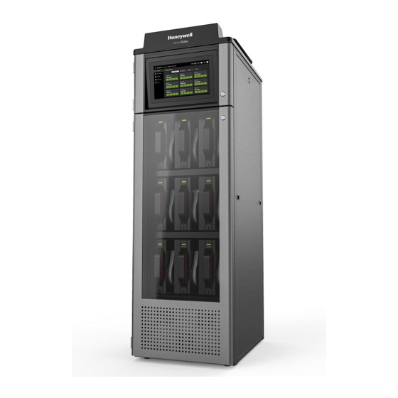
System Components The following photos illustrate the Vertex Edge System views, ports, connections and controls. Front view 1. Sample tubing connections 2. Exhaust and wiring port 3. System controls (behind screen) 4. Analyzer 5. Pump Vertex Edge System User Manual... - Page 13 1. System Exhaust 0.5 in (12.7 mm) tubing 2. AC Input 0.75 in pipe thread 3. Alarm Wiring Conduit Plates - 1.5 in (38.1 mm) NOTE: Please note that exhaust tube is push to connect. Vertex Edge System User Manual...
- Page 14 Module Front - Door Closed 1. Protective panel over touch screen 2. Analyzer Slot 3. Tier 1 4. Tier 2 5. Tier 3 6. Analyzer Status LED Vertex Edge System User Manual...
- Page 15 Analyzer side panel — Exterior Needle Valve for flow adjustment Optics Block RFID reader Take-up reel Tape encoder roller Status LED Vertex Edge System User Manual...
- Page 16 Analyzer side panel — Interior 1. Analyzer Main Board 2. Sample pressure transducers 3. Sample flow transducers 4. Optic blocks 5. Tape advance motor 6. Status LED 7. Locking solenoid Sample tubing connections Vertex Edge System User Manual...
- Page 17 Monitor/Computer power Pump 1 Power Connector* Pump Over temp sensor / Fan power Pump 2 Power Connector* Not Used Ethernet Hub Power Connector* Modbus RTU Modbus RTU Ground Screw * AC connections System Control Unit Vertex Edge System User Manual...
- Page 18 Analyzer — Front view 1. Analyzer status LED 2. Product label 3. Analyzer Release Slot Back of Analyzer 1. Internal Ethernet Communication Cable 2. Tubing Harness 3. Analyzer Power Connection 4. Securing screws for tubing harness Vertex Edge System User Manual...
- Page 19 Chemcassette 1. Chemcassette directional flow Vertex Edge System User Manual...
-
Page 20: Analyzer Modules
• Sample atmosphere runs from the location to the Vertex Edge System via a line • Each of the 72 sample tubing connections on the Vertex Edge System corresponds to a point. A sample line can be connected directly to a single point or multiple points. -
Page 21: Chemcassette Detection System
The Chemcassette Analyzer module is a self-contained, microprocessor-controlled analyzer that occupies one slot in a Vertex Edge tier. Sample lines and the vacuum source are connected to the Chemcassette via a single 9-tube connector to develop a better stain for better sensitivity and reliability. - Page 22 When monitoring a location, the system detects and measures a specific gas or a family of gases in the sample. The microprocessor in the analyzer module interprets the data and responds appropriately. In the Closed Loop Optics (CLO) detection system, a reference detector monitors and controls the intensity of the LED. Vertex Edge System User Manual...
- Page 23 • Revision level • Expiration date of the tape • Chemcassette® leader parameters The module uses a leader on the Chemcassette tape to allow calibration of the optics every time a new tape is installed. Vertex Edge System User Manual...
-
Page 24: Vacuum Pumps
Note: The exhaust line from the Vertex Edge should not exceed 50 feet. The pumps are located in the bottom of the Vertex Edge System cabinet on a sliding plate to help disconnect the tubing for ease of maintenance. Three cooling fans circulate air over the pumps. -
Page 25: Data Acquisition Computer
Data Acquisition Computer The data acquisition computer (DAq) is the central processor for the Vertex Edge System. It configures the analyzers, stores data and provides a network interface for data transfer to other computers. System display and operator control is through an on-screen keyboard. - Page 26 Please note: when using the USB 3.0 ports to connect a USB flash drive, please use caution when closing the panel door with this installed. If the drive is physically too large, it can become damaged when closing the door. Do not use the USB 2.0 ports. Vertex Edge System User Manual...
-
Page 27: Installation
6. Data Acquisition System. Installation Step 1: Surveying the Installation Site A survey of the site helps you to make important decisions before installing your Vertex Edge System. Topics in this section are intended to assist you with appropriate placement of the Vertex Edge System and in determining if you have special filtering needs at the sampling location. - Page 28 Monitor Dimensions Monitor dimensions are important factor in monitor placement. The Vertex Edge System is 24 in. (61 cm) wide, 34-1/2 in. (88 cm) deep and 76 in. (193 cm) in height. The system with 9 analyzers weights about 900 pounds (408 kg). Allow for 24 in. (61 cm) door swing; 5 in. (12.3 cm) at rear and 5 in.
- Page 29 Installation Drawings Vertex Edge System User Manual...
-
Page 30: Optional Installation Step 2: Floor Mounting
Optional Installation Step 2: Floor Mounting 1. Attach the bracket to the front and rear of the Vertex Edge cabinet, including the supplied hardware. 2. Anchor the bracket to the floor with the appropriate mounting hardware base on installation (hardware not provided). -
Page 31: Installation Step 3: Installing Sample Lines
• Analyzers with unused points require a filter. Filter kit 1295A0702 is recommended. • If an analyzer is installed in the Vertex Edge with a Chemcassette tape, the optics may need cleaning before activating a previously unused point(s). - Page 32 Remove the pipe to measure the insertion depth. CAUTION Improper installation of the tube into the connector results in dilution of the sample. Vertex Edge System User Manual...
- Page 33 Excess amounts of dirt in the filters reduces the sample flow, raises sample vacuum and may affect concentration readings of the analyzer. See Specifications, to determine the proper filter type to use with each target gas. Vertex Edge System User Manual...
-
Page 34: Installation Step 4: Installing The Pump Exhaust Line
Installation Step 4: Installing the Pump Exhaust Line This section describes exhaust connections and installation. The Vertex Edge is equipped with a vacuum pump located at the bottom of the Vertex Edge cabinet. The pump exhaust line connects to the manufacturing facility central toxic exhaust system. -
Page 35: Installation Step 5: Electrical Power
AC Source Requirements: Operating Voltage: 230 VAC ± 10% (under load) @ 50/60Hz; 15 Amps maximum, single phase. The Vertex Edge system requires a dedicated AC source rated at 230 VAC @ 50/60Hz, 15 Amp single phase providing hot, neutral, and ground lines. Line voltage should fluctuate no more than ±... - Page 36 4. White Neutral 5. Vertex Edge side, prewired. Verifying Proper AC Power Connection Before powering up the Vertex Edge system, verify the connections using a multimeter to determine the connections are correct and correct voltages are present at the power connection.
- Page 37 After confirming line and neutral connections and the operating voltage is within the specified range, power up the Vertex Edge® and check the operating voltage again to assure the voltage under load is within the specified range for safe operation.
- Page 38 Honeywell Analytics service representatives should perform these tasks. Honeywell Analytics is not liable for any damages caused by incorrect installation by unauthorized or unqualified third parties, of electrical apparatus to the Vertex Edge monitor Design Characteristics • UL-3R enclosures for indoor and outdoor service •...
- Page 39 Secondary Voltage Interconnect Connect Lines to: X2 to X3 X1 and X4 Connect X4 to Ground and Shield Set-Up wiring 0060-1021 as Step-Up Transformer 208v to 240v 120/208/240/277 Volt Primary, 120/240 Volt Secondary, Taps: None Vertex Edge System User Manual...
- Page 40 125% of rated primary current (or next highest standard rating) Example 2. If the branch circuit feeding the transformer has overcurrent protection to meet the individual protection requirements in Example 1, then individual transformer protection is not required. Vertex Edge System User Manual...
- Page 41 Example 4. If the branch circuit feeding the transformer has overcurrent protection to meet the individual primary overcurrent protection requirements in Example 3, then individual primary protection is not required. Secondary OCP is required as shown as follows. Vertex Edge System User Manual...
- Page 42 Transformers shall be provided with six 2.5% full capacity taps – two above and four below primary rated voltage. General purpose transformers are classified as isolation transformers. Enclosures Vertex Edge System User Manual...
- Page 43 301 to 500 KVA 60 db Transformers, 15 KVA to 500 KVA, shall incorporate a UL recognized 2200C insulation system and exhibit a maximum 1500C temperature rise above a maximum ambient of 400C under full load. Vertex Edge System User Manual...
-
Page 44: Installation Step 6: Data Acquisition System
Installation Step 6: Data Acquisition System The data acquisition computer or DAq is the main computer in the Vertex Edge System. The Vertex Edge System can be connected to an external Ethernet network at the port shown. CAUTION Do not connect an external network to the Vertex Edge Ethernet hub. Use only the external Ethernet connection on the back of the data acquisition computer. - Page 45 PDU. NOTE To maintain EMC certification, the ethernet cable should make 4 loops through the supplied ferrite cable clamp. The clamp should remain on the outside of the Vertex Edge System enclosure. Vertex Edge System User Manual...
-
Page 47: Device Operations
Upon power-up, the DAq automatically starts Linux and loads the Vertex Edge HMI program. After the startup sequence, the Vertex Edge HMI main screen opens as below. The start-up time may take several minutes, and the default user is Viewer. - Page 48 NOTE Any time the Vertex Edge System is powered up, loss of communications may cause maintenance faults. See Section See "Acknowledge Notifications" on page 70 for more information. for instructions to clear faults. NOTE Use the System Manager->Region and time menu to change the time and date on your Vertex Edge System.
- Page 49 Power On Use the rack power switch behind the touch screen door to power up the Vertex Edge System. 1. Open the touch screen door. 2. Turn on the rack power switch. 3. Turn on the power switch to appropriate analyzers.
- Page 50 Upon power-up, the DAq automatically starts Linux and loads the Vertex Edge HMI program. After the startup sequence, the Vertex Edge HMI main screen opens as below. The start-up time may take several minutes, and the default user is Viewer.
- Page 51 Creating Profile process. 6. Tap SAVE & INSTALL whether you want to install this new profile in the system. If you do not want to install this project, tap SAVE AS and enter a profile name. Vertex Edge System User Manual...
- Page 52 7. Tap INSTALL TO SYSTEM to complete installation. Alternatively you can select the profile in the profile list and install it to the Vertex Edge system later. Vertex Edge System User Manual...
- Page 53 Non-Latching Gas Alarm A latching gas alarm activates when a gas concentration reaches a level 1 or level 2 alarm setting. The latching gas alarm remains until an authorized operator resets the alarm. Non- Vertex Edge System User Manual...
- Page 54 The default setting is 04:00 indicating that the Vertex Edge will run three successive TWA periods from 04:00 to 11:59, 12:00 to 19:59, 20:00 to 03:59. Remember, the Vertex Edge System uses a 24-hour clock. For example, to set the first TWA to 3:00 P.M., enter 15:00. The system automatically sets the beginning times of the second and third TWA periods at 8-hour intervals from the time entered for the first TWA period.
- Page 55 Generate low CC fault Vertex Edge software tracks the amount of Chemcassette® tape remaining on the supply reel and triggers a low tape event when remaining tape is less than Days Before Due. Choosing OFF disables the low tape event.
- Page 56 Select the analyzer to configure and tap on the EDIT button. Activate the selected analyzer and select the gas family. If you want to apply same configurations to all analyzers, tap on the APPLY TO ALL button. Vertex Edge System User Manual...
- Page 57 Select to display concentrations in milligrams per cubic meter. If this option is not selected, Vertex Edge displays concentrations in parts-per-million (ppm) or parts-per-billion (ppb). Select a target gas for the point and enter the gas location of the place where gas is sampled.
- Page 58 When this option is ON and non-zero gas concentration is detected, an informative event will be recorded and non-zero warning status will be reported to DAq. The point with non-zero warning will blink in green. Vertex Edge System User Manual...
- Page 59 Vertex Edge System User Manual...
- Page 60 To copy analyzer/point settings from one analyzer to other analyzers, tap on the COPY button. Select the source analyzer in the analyzer list and check the analyzers where same configurations are applied. Vertex Edge System User Manual...
- Page 61 To export a profile, plug in USB flash drive in the DAq. Select the profile in the list and tap EXPORT to export it to USB flash drive Enter a profile name and select the location where the profile will be exported After selecting the location, tap NEXT and profile exporting will be complete. Vertex Edge System User Manual...
- Page 62 To import a profile from USB flash drive, tap IMPORT Select the profile in the Import Profile window and tap NEXT. Selected profile will be imported and shown in the profile list of Profile Manager Vertex Edge System User Manual...
- Page 63 Vertex Edge System User Manual...
- Page 64 Login and Logout To protect the integrity of the system, the Vertex Edge System classifies the access levels as a viewer, an operator and an administrator. If you require access to a protected menu, you must log in under a user role with permission to use that menu. The Vertex Edge System administrator assigns a role to the user accounts.
- Page 65 Default user ID and password are Admin / Admin for an administrator role and Operator / Operator for an operator role. NOTE Upon initial installation and login, it is strongly recommended to change the password of the default users in accordance with the password complexity. Vertex Edge System User Manual...
- Page 66 Type a username, password according to the password complexity and select an appropriate role to the user. NOTE Passwords need to consist of at least 8 characters and include a lowercase, an uppercase and a special character and a number. Vertex Edge System User Manual...
- Page 67 To edit users, select the target user in the list and tap on the EDIT USERS button. User role and password for the user can be changed by an administrator. Alternatively, logged user can change one’s password by tapping on the CHANGE PASSWORD button. Vertex Edge System User Manual...
- Page 68 Overview screen. Service due of all connected analyzers will be shown graphically such as remaining CC tape life, remaining days to Optic cleaning and remaining days to filter replacement. Vertex Edge System User Manual...
- Page 69 Vertex Edge System User Manual...
- Page 70 The graphical representations of the point status at the bottom of point status box are the same as the Overview screen. 3. Tap the back overview button to return to the Overview screen. Vertex Edge System User Manual...
- Page 71 1. From the upper right side of the main screen, tap on any of the notification icons to view notification details. The selected icon is highlighted in blue. The number within the circles indicate the sum of events for each notification. Vertex Edge System User Manual...
- Page 72 Alternate the pump every 6 months. 1. From the main screen, tap on the Pump maintenance button . The pump icon is highlighted in yellow when pump uptime is reaching to the end and service is required. Vertex Edge System User Manual...
- Page 73 6. Optionally the temperature status in the pump module and high pressure status at exhaust line can be checked. When there is any issue in temperature and exhaust pressure, the text of Temperature and Exhaust condition will be highlighted in yellow. Vertex Edge System User Manual...
- Page 74 You can turn ON or OFF a pump when all the analyzers are out of the monitor mode. 1. In the left navigation panel, tap OVERVIEW 2. Tap the pump button 3. In the Pump Maintenance window, tap PUMP OFF or PUMP ON as needed. Vertex Edge System User Manual...
- Page 75 3. In the Components status bar, tap on the selected analyzer's gas family name. 4. In the Operation Control window, select Monitoring mode, ON or OFF NOTE The Optic gate is closed when Monitoring mode is ON. Vertex Edge System User Manual...
- Page 76 3. In the Components status bar, tap on the selected analyzer's gas family name. 4. In the Operation Control window, shift the Optic Gate slider to OPEN. NOTE The Optic gate is closed when Monitoring mode is ON. Vertex Edge System User Manual...
- Page 77 1. In the left navigation panel, tap OVERVIEW 2. Tap on the selected analyzer. 3. In the Components status bar, tap on the selected analyzer's gas family name. 4. In the Operation Control window, tap RELEASE next to Analyzer lock Vertex Edge System User Manual...
- Page 78 1. In the left navigation panel, tap OVERVIEW 2. Tap on the selected analyzer. 3. In the Components status bar, tap on the gas family name. 4. In the Operation Control window, tap TAPE ADVANCE next to Chemcassette Vertex Edge System User Manual...
- Page 79 Tap ADJUST OPTICS and clean the Optics block by referring to Clean the Optics section in Maintenance first. Tap ADJUST OPTICS and reset the count. 6. Optional Step. Tap the Reset Count button to Reset the configured Optic cleaning interval. Vertex Edge System User Manual...
- Page 80 In the Components status bar, tap on the OPTIC Status button Alternatively Tap ADVANCED DIAGNOSTIC to view LED drive levels for eight points and check whether the LED drive levels are within the recommended range. Vertex Edge System User Manual...
- Page 81 To troubleshoot the condition, disconnect the sample line at the inlet port at the top of the Vertex Edge cabinet. Securely plug the inlet port and repeat the above leak check procedure.
- Page 82 In the left navigation panel, tap OVERVIEW Tap on the selected analyzer. In the Components status bar, tap on the Flow Rate button Flow Adjust Screen Vertex Edge System User Manual...
- Page 83 Continue through all analyzers populated in the system and Press “Adjust Flow” so that flow is turned on for all of the analyzers in the system. Once all analyzer flow is ‘on’, press Vacuum Levels (as shown below). View of Vacuum Level Screen Vertex Edge System User Manual...
- Page 84 At higher altitudes with many analyzers installed, and/or a system on a 50Hz mains, the system vacuum may not be able to achieve 11inHg. In this case, the maximum achievable sample point flow rate shown may be reduced by up to 20%.. CAUTION Vertex Edge System User Manual...
- Page 85 Supply vacuum should be readjusted whenever analyzer(s) are installed to or removed from the rack. Vertex Edge System User Manual...
- Page 86 Repeat for all analyzers until the entire system is complete. Once complete, press STOP FLOW for each analyzer. This will stop for the flow for each analyzer. Once all analyzers have the flow stopped, the pump will turn off. Vertex Edge System User Manual...
- Page 87 Either the regular replacement window highlighted in green or the expired time window highlighted in yellow is displayed. 4. End of sample line filters should be replaced on a regular interval of 3 months 5. Tap the Reset Count button to reset the replacement due days. Vertex Edge System User Manual...
- Page 88 This counter should be used with end of sample line filters only. NOTE Internal filters protecting the orifice should be inspected and cleaned on a regular interval of 6 months. See the See "Orifice Filter Inspection, Cleaning & Replacement " on page 118 for more information.. Vertex Edge System User Manual...
- Page 89 2. Tap in the Listed by time tab. A list of all events is displayed. 3. In the Listed by Time screen, you can filter the information. Export the Events History Insert a USB flash drive to Vertex Edge HMI PC. Tap the Export icon to export the event histories to CSV file.
- Page 90 Select a USB drive to export the event histories and touch NEXT button. Once exporting is complete, the "Exporting is completed" screen will be shown as below. It may take several minutes depending on number of events to be exported. Vertex Edge System User Manual...
- Page 91 Vertex Edge System User Manual...
- Page 92 In the left navigation panel, tap Event History Tap in the Listed by Analyzer tab. A list of all analyzer events is displayed. Tap on the More Filters button to view the events of specific Points. Vertex Edge System User Manual...
- Page 93 View System Version Information Version Manager shows version information of Vertex Edge system components such as Analyzer, DAq and PDU. The version information includes FW version, HMI application version, part numbers, serial numbers and rack ID. From the main menu, go to System Manager > Version Manager Tap on the HMI Version or PDU Version tab to view detailed version information of the system components.
- Page 94 From the main menu, go to System Manager > Version Manager Insert the USB flash drive to any available USB port of the Vertex Edge HMI PC. Tap on the IMPORT button to copy an update file from USB flash drive to HMI PC Select an analyzer update file.
- Page 95 If there is any communication error or any issue in updating the firmware, the red dot will be shown instead. Tap on “Next” button when FW update is done with two green dots and it moves back to Version Manager screen with updated version information. Vertex Edge System User Manual...
- Page 96 Vertex Edge System User Manual...
- Page 97 System Shutdown CAUTION Failure to properly shut down the Vertex Edge could result in system file corruption. Go to Runtime Operation and stop monitoring mode for all analyzers. Go to Settings->System Switch and touch System Shutdown Touch Proceed on the confirmation screen Set all analyzer switches (2) on PDU to "Off"...
- Page 98 1) Main power ON/OFF switch 2) Analyzer power switches Vertex Edge System User Manual...
- Page 99 Pump stem and o-ring 6 months Valve filter 1 year Supply Vacuum Filters 3-6 months Alternate Pumps 6 months Optics Cleaning 1 year or as needed System File Maintenance 1 year or as needed Orifice Filter 3-6 months Vertex Edge System User Manual...
- Page 100 Replace the Chemcassette Change the Vertex Edge Chemcassette tape for any of the following reasons: Scheduled end-of-tape service Low Chemcassette warning Chemcassette has expired End of Chemcassette 1. In the left navigation panel, tap OVERVIEW 2. Tap on the selected Analyzer.
- Page 101 (as seen in the picture below. The HMI screen also shows the leader tape configuration). The alignment is essential to adjust and verify the Optics module before gas monitoring. Vertex Edge System User Manual...
- Page 102 Do not rewind the CC to reuse the leader tape. If using the leader tape, the user will need to manually install the leader tape for each color to be tested. Vertex Edge System User Manual...
- Page 103 14. After completing the Optics adjustment/Verification, Tap NEXT 15. In the Start Monitoring Mode window, tap START if you want to start the monitoring mode. If not, Tap IDLE. The new Chemcassette information is displayed. Vertex Edge System User Manual...
- Page 104 Replace an Analyzer The Vertex Edge rack is designed for quick replacement of major components. You may replace the Chemcassette analyzer while other analyzers continue to monitor. WARNING: Do not connect or disconnect anything from the Power Distribution Unit (PDU) while energized.
- Page 105 8. Unscrew the two screws located at the top and bottom of the manifold bracket. 9. Remove the tubing harness (2) carefully and remove internal Ethernet cable (1) and power connector (3) from the Analyzer. Vertex Edge System User Manual...
- Page 106 10. Unlock the latch on the top of the Analyzer (as shown) and pull out. 11. After removing the Analyzer, make sure exhaust port of the analyzer be blocked with plug as shown in the picture below. Vertex Edge System User Manual...
- Page 107 NOTE Failure to block the analyzer exhaust port will impact the flow system for the running unit. Vertex Edge System User Manual...
- Page 108 IMPORTANT: The 2 screws need to be tightened to fully secure. If these are not tightened, the unit will leak. 6. Connect the Analyzer internal Ethernet cable (1) and power connector (3) from the Analyzer. Vertex Edge System User Manual...
- Page 109 Repeat in and out action to loosen slide. Push analyzer into cabinet. Return to Service 1. Turn analyzer power switch on. 2. Re-install the Configuration Profile. 3. Install the Chemcassette. 4. Return analyzer to monitor mode in Runtime Options Menu. Vertex Edge System User Manual...
- Page 110 Replace a Pump The Vertex Edge System includes two vacuum pumps. One pump operates while the other is idle. You may replace a defective pump while the other pump continues to operate. NOTE You may replace a pump only when the system places it in off condition. Do not replace an operating pump.
- Page 111 Power connector removal are in steps 4-5. Uninstall the electrical connector on the side of the pump Pull the white tab out Push down on the black tab and pull back on the connector Vertex Edge System User Manual...
- Page 112 Once pump cable is disconnected, tuck it under the pump head on the pump plate To open the pump drawer, pull up on the two knobs securing the pump bed and twist to unlock them. Vertex Edge System User Manual...
- Page 113 If replacing Pump 2, disconnect the power connector as covered in steps 4-5. The pump fittings are removed by pushing in on the silver plate and pulling up on the fitting at the same time Vertex Edge System User Manual...
- Page 114 Disconnect the vacuum side (silver fitting) Disconnect the exhaust side (black fitting) Once disconnected the fittings can be placed to the side or on top of the pump Vertex Edge System User Manual...
- Page 115 (Note: The picture shown has the pump drawer opened and unlocked. This orientation is to show the pump pin and plate. This step should be performed in the locked position. The locked position will prevent the drawer from moving while swapping out the pump.) Vertex Edge System User Manual...
- Page 116 2 removed. This step should be performed in the locked position. The locked position will prevent the drawer from moving while swapping out the pump.) Lift up the tubes and connectors, then slide in a new pump assembly Vertex Edge System User Manual...
- Page 117 With the new pump installed, unlock and pull out the pump drawer. With the pump drawer opened, reconnect the vacuum, exhaust, and ac connector. Close the pump drawer. Close and secure the pump cooling fan door. Vertex Edge System User Manual...
- Page 118 Replace Exhaust by-Pass Filters Remove old filters by depressing the quick connect fitting Pull out old filters and install new filters, ensure the arrow on the new filter is point in towards the valve as shown. Vertex Edge System User Manual...
- Page 119 Remove the orifice Panel on the side of the Analyzer by unscrewing the thumbscrew Thread in the orifice removal tool 1502-0166 or a 6-32 screw into the orifice cartridge and pull back to remove it from the manifold Vertex Edge System User Manual...
- Page 120 Once removed inspect the cartridge for any debris on the surface of the filter. If there is any debris clean it with compressed air. Once cleaned replace the orifice into the cavity it came from. Check that the orifice is fully installed into the manifold Vertex Edge System User Manual...
- Page 121 Clean the touch screen display with a lightly moistened towel. Do not spray cleaner directly onto the glass. Excess liquid will run down the screen and interfere with operation. For further reference, refer to the Touchscreen User Manual for any additional information. Vertex Edge System User Manual...
- Page 122 2. Open the Optics Block Gate. 3. Remove the Chemcassette by releasing and pulling out the analyzer. 4. Open the Vertex Edge side panel. 5. Remove tubing (shown in photo) one at the time and blow out with compressed air.
- Page 123 CHAPTER Additional Information Learn about strategic information related to the Honeywell Vertex™ Edge Detector. Specifications OVERALL SYSTEM DIMENSION Size 76” x 24” x 35” Weight - Full Full ~900lbs (~408kg) loaded condition Weight - Empty Empty ~655lbs (~297kg) rack ANALYZER Size 22”...
- Page 124 Flow varies depending on tube length. For more information refer to See Flow "Nominal Transport Times" on page 145 for more information. Transportation For more information refer to See "Transport Time " on page 140 for more Time information. Vertex Edge System User Manual...
- Page 125 Detectable Gases Vertex Edge System Chemcassette analyzers are continuous monitoring instruments. The initial analysis period listed in the following table varies based on the programmed alarm levels. This period is valid only after the system pulls a new Chemcassette window. Increasing the programmed alarm levels will decrease the initial sample period.
- Page 126 100 ppb 0-500 ppb 3-500 ppb XP6 Hydrides (1507- with 100 ppb AsH3 gas) 9300) Arsine XP6 (AsH3) Low 0.5-1.9 ppb 5 ppb 0.5 ppb 0.3 ppb 2.5 ppb 5 ppb 0-50 ppb <60 sec Vertex Edge System User Manual...
- Page 127 30-99 ppb Hydrogen Bromide XP <200 sec (Alarm @ 0.2 ppb 2 ppm 30 ppb 20 ppb 200 ppb 400 ppb 0-2000 ppb 100-399 ppb (HBr) Low Level with 0.4 ppb HBr gas) 400-2000 ppb Vertex Edge System User Manual...
- Page 128 200-399 ppb with 1000ppmHF gas) 400-2000 ppb *Due to U.S. Government regulations, this range may be subject to restrictions requiring special licensing for certain countries outside North America. Contact Honeywell for eligibility information. Boron Trifluoride XP4 0.04 0.05-0.99 ppm <100 sec (Alarm @0.1ppm 0.1 ppm...
- Page 129 2 ppm 0-10 ppm 2.0-3.90 ppm XPV Chlorine-II with 0.2ppm F2 gas) 4.0-10.0 ppm (1295-0560) Fluorine XP-Cl2-II (F2) 0.1 ppm 0.05 ppm 0.03 0.1 ppm 0.2 ppm 0-1.0 ppm 0.05-0.199 ppm <85 sec (Alarm @ 0.1ppm Vertex Edge System User Manual...
- Page 130 200cc/min. The performance efficiency including response accuracy and response time can deviate depending on sample gas conditions. (ex. The response time will be extended at higher RH condition due to absorption onto the sample line.) Vertex Edge System User Manual...
- Page 131 Maintenance Faults A maintenance fault indicates the Vertex Edge System requires attention but is continuing to monitor. Event Description Possible Cause Resolution Check sample line and line filter. Excessive point vacuum due to clog or kinked sample line Clean the sample line and replace filter.
- Page 132 Single pump failure Unused slots not plugged Install connector plug on unused slot Check valve on inactive pump leaking Replace check valve Contact Honeywell Analytics Service Clean optics. Optic block dirty Contact Honeywell Analytics Service. Optics Block Dirty - Cleaning...
- Page 133 Unable To Log event data File system corrupted Contact Honeywell Analytics Service Software version mismatched New analyzer was installed into the Vertex Edge rack that contains a different software Upgrade analyzer Software among Analyzers revision than the other analyzers This Chemcassette is nearing its...
- Page 134 Gate motor driving failure Motor does not operate Check motor connections to Analyzer PCB in analyzer Bad sensor or cable Check sensor connection to Analyzer PCB. Contact Honeywell service Poor grounding Replace Analyzer, Contact Honeywell service Optics signals are noisy...
- Page 135 Optics LED not properly calibrated Perform Replace CC or Adjust Optics operation to recalibrate Optics drive unusually low Optics board defective Replace the Optics Block. Contact Honeywell service Analyzer CPU defective Replace Analyzer, Contact Honeywell service Optics LED not properly calibrated...
- Page 136 Perform Replace CC or Adjust Optics operation to recalibrate LED degradated Replace the optics block Optics board defective Replace the Optics Block. Contact Honeywell service Chemcassette leader not tight or improperly positioned during Reload Chemcassette white to light gray calibration...
- Page 137 Hardware failure Contact Honeywell Analytics Service Re-install analyzer software Analyzer SW corrupted Software installation failure Replace Analyzer, Contact Honeywell service Internal SW fault at analyzer Internal SW operation failed Reboot the Analyzer. Contact Honeywell service. Vertex Edge System User Manual...
- Page 138 Information Events The Vertex Edge System enters informational and other non-fault events into the event history database. These do not require any action by the user. Use the event history to check the status of the instrument. Event ID Description...
- Page 139 Optics Program Failed 2038 Ctrl Module Programmed Successfully 2039 Ctrl Module Program Failed 2040 PDU Module Programmed Successfully 2041 PDU Module Program Failed 2042 Gas table updated 2043 Rejected gas table file 2044 Imported license file successfully Vertex Edge System User Manual...
- Page 140 Rejected license file 2046 Failed to verify update file 2050 Reset Single Alarm/Fault. 2051 Reset All Alarms and Faults 2052 Reset All Alarms and Faults - Modbus 2053 Analyzer Configuration updated 2054 Point Configuration updated Vertex Edge System User Manual...
- Page 141 Normal barometric pressure [inHg] Multiplier 29.92 1.00 29.39 0.98 1,000 28.86 0.96 1,500 28.33 0.93 2,000 27.82 0.91 2,500 27.32 0.89 3,000 26.82 0.89 3,500 26.33 0.88 4,000 25.84 0.86 5,000 24.9 0.83 6,000 23.98 0.80 Vertex Edge System User Manual...
- Page 142 DAq. To confirm a non-responsive DAq as opposed to frozen/locked- up, check the clock located in the upper right hand corner of the Vertex Edge HMI window. If the clock is still advancing, then the DAq CPU is not frozen/locked-up and your local Authorized Service Center needs to be contacted for assistance.
- Page 143 Close and reattach the Analyzer cover, reconnect the Ethernet Communications Cable and slide the Analyzer into the cabinet. Fix an Unresponsive Vertex Edge Touch Screen Completely resetting the computer can resolve many issues that cause a frozen/unresponsive screen. Follow these steps to perform a hard reset: Remove any USB devices from the USB ports of the HMI PC if non-default USB devices were inserted.
- Page 144 Turn on the PC by pressing the Power button. Wait until HMI application starts up Check if touch screen is responsive and all connected analyzers are shown on Overview screen NOTE When this occurs, the system will continue to monitor gas. Vertex Edge System User Manual...
- Page 145 Filters have an arrow on the side of the filter pointing in the direction of airflow toward the Vertex Edge System. Replacement of filters is site dependent. Filter A - P/N 780248 Filter B - P/N 1830-0055 Filter C - P/N 1991-0147 The following table shows sample filter requirements.
- Page 146 Titanium Nominal Transport Times The following table shows the time required for samples to move from the sampling point to the Vertex Edge System for various lengths of sample lines. 0.25" Outside Diameter Tubing 0.190"(Thin Wall) ID Length in feet...
- Page 147 XP4-V for PHOSGENE 1257-9307 XP6-V for Amines/Ammonia 1507-9309 XP6-V for Hydrides 1507-9300 End of Line Particulate Sample Filters For non-corrosive gases 780248 For corrosive gases 1830-0055 Replacement membrane, for corrosives (pk/100) 0235-1072 For corrosive gases 1991-0147 Vertex Edge System User Manual...
- Page 148 Transformer 208/240 VAC 60 Hz, 5 KVA 0060-1021 Needle Valve 0235-1219 Power Distribution Module (complete) 1502A0210 Pump Assy, 220VAC High Flow 1502A0254 Pump Rebuild Kit 0235-1205 Pump Stem and O-Ring 0235-1212 Neoprene Isolation Mount 0950-1061 Thermal Switch (170F) 0170-0082 Vertex Edge System User Manual...
- Page 149 Spare Part Numbers Fan, 24VDC 0220-0023 Vacuum Fitting Assembly - Exhaust 1295K0547 O RING NO.112 VITON BLUE TEFLON COATED 0235-0187 Unused Point Filter Kit - Inlet Extension with Dust Filter 1295A0702 Blocking Plug 0235-1318 Orifice/Filter Assembly 1502A0155 Vertex Edge System User Manual...
- Page 150 Modbus RTU Enable or Disable Baud rate (User Selectable) 9600 19200 (Default) Data bits 8 bits Parity (User Selectable) None (Default) Even Stop Bits Slave ID option Used for each Analyzer (Default 1-9 as shown) Vertex Edge System User Manual...
- Page 151 Modbus TCP/IP and Web interfaces IP Configuration DHCP (Default) Static IP: Static IP address, Gateway, DNS Modbus TCP/IP Enable or Disable Web interface on port 80 Enable Disable (Default) Encrypted web interface on port 443 Enable Disable (Default) Vertex Edge System User Manual...
- Page 152 40083 Az 2-3 Status Integer unsigned 40084 Az 3-1 Status Integer unsigned 40085 Az 3-2 Status Integer unsigned 40086 Az 3-3 Status Integer Floating 40087 Pt 1-1-1 GasConc Little endian point … … … … Vertex Edge System User Manual...
- Page 153 40402 Az 1-1 active fault code integer and maintenance faults, the lowest instrument fault will be returned … … unsigned 40410 Az 3-3 active fault code integer signed 40411 Az 1-1 CCDays integer … … Vertex Edge System User Manual...
- Page 154 Pt 3-3-8 AlarmThres1 R/W (function code 0x10) point Floating 40596 Pt 1-1-1 AlarmThres2 R/W (function code 0x10) point … …. Floating 40738 Pt 3-3-8 AlarmThres2 R/W (function code 0x10) point Floating 40740 Pt 1-1-1 FullScale point Vertex Edge System User Manual...
- Page 155 … … 43168 Az 3-3 Ctrl SW Ver Byte[3] Az 1-1 43170 Opt1 SW Byte[3] first byte: major, second byte: minor, last two bytes: build number Vertex Edge System User Manual...
- Page 156 6: MFault (0: no alarm, 1: in Mfault) Bit 7: IFault (0: no alarm, 1: in Ifault) Bit 8: Sim Alarm 1 (0: no alarm, 1: in alarm) Bit 9: Sim Alarm 2 (0: no alarm, 1: in alarm) Bit 10: over-range (0: no alarm, 1: in over-range) Bit 11: Warning below AL1 (0: no alarm, 1: in warning) Bit 12 ~ 15: Reserved Single Analyzer information is Vertex Edge System User Manual...
- Page 157 0x0 If there are active multiple instrument faults, the lowest instrument fault will be returned If there are both instrument 40046 Az active fault code integer and maintenance faults, the lowest instrument fault will be returned signed 40047 Az CCDays integer signed 40048 Az FilterLife integer 40049 Az PumpMaintDays signed Vertex Edge System User Manual...
- Page 158 Up to 5 characters Based on measurement unit it should provide unit strings as below. 0: ppb, 2: %Lel, 4: mg/m3, 8: ppm, 12: %Vol … …. 40333 Pt 8 GasUnit string[6] 40336 Az Label string[26] 40349 unused Byte Vertex Edge System User Manual...
- Page 159 Can be used same as rack ID. null terminated. Up to 25 characters 40397 Az PDU SW Ver Byte[3] First byte: major, second byte: minor, last two bytes: build number Unsigned 65001 Az Reset alarms & faults Nonzero value Integer Vertex Edge System User Manual...
- Page 160 HMI PC Security Considerations Connectivity The Vertex Edge HMI PC has two one-gigabit ethernet ports, one for connecting to the internal analyzer network, and one for connecting to an external network. The Vertex Edge HMI PC has no wireless connectivity.
- Page 161 HTTPS Connections When making a connection to the Vertex Edge HMI PC via HTTPS, it will be necessary to accept the certificate. A message like the one using Google Chrome will be shown: Tap on the Advanced button, and select “Proceed to <some IP> (unsafe).”...
- Page 162 Service Order Number and a full description of the fault at buyer’s expense. If no description of the fault is provided, Honeywell reserves the right to charge an investigation fee. If the product is found to be of “no fault”, Honeywell reserves the right to charge an investigation fee and return same product to buyer after the investigation fee and transport cost are reimbursed in full.
- Page 163 After the effective date this warranty supersedes all existing warranty statements and Honeywell makes no other warranty expressed or implied except as stated above. Vertex Edge System...
- Page 164 Honeywell Analytics 405 Barclay Boulevard Lincolnshire, Illinois 60069, USA is.gas.techsupport@honeywell.com Tel: +1 847 955 8200 Toll free: +1 800 538 0363 Scan this code for further reference to Vertex Edge Systems on Honeywell Analytics website Vertex Edge System User Manual...
- Page 165 © September, 2021 1998-2002_EN_RevA1_VertexEdge_UserManual Vertex Edge System User Manual...