Table of Contents
Advertisement
Quick Links
Advertisement
Table of Contents

Related Manuals for Honeywell VERTEX C


Summary of Contents for Honeywell VERTEX C
- Page 1 USER MANUAL VERTEX C ANALYZER...
-
Page 2: Table Of Contents
Contents Safety ................................... 3 Trademarks ..................................3 General Safety ................................. 3 Continuous Monitor Symbols ............................3 FCC Compliance Statement ............................. 4 NCC Compliance Statement ............................4 Connectors..................................6 Introduction ................................. 7 Analyzer side panel — Exterior ............................ 7 Analyzer side panel — Interior............................. 9 Analyzer —... -
Page 3: Safety
General Safety Follow all installation and operational instructions to ensure the safe and reliable operation of this unit. If this monitor is used in a manner not specified by Honeywell Analytics Inc., the protection provided by the equipment could be impaired. -
Page 4: Fcc Compliance Statement
Protective conductor terminal (ground terminal) EMC Considerations Your Honeywell Analytics continuous gas monitor has been designed to comply with Electromagnetic Compatibility (EMC) standards applicable at the time of its manufacturing. The design includes filtering, shielding and bypassing techniques. At the time of certification, simulated customer Input/ Output (I/O) schemes were tested. - Page 5 devices must be susceptible with the interference from legal communications or ISM radio wave radiated devices. Cabling At the very minimum, all cables should include a braided shield. Ideal results have been obtained with twisted pair cabling which has a foil shield surrounding each pair plus foil and 90% braid shielding around the bundle. In addition, ensure local electrical code requirements are met.
-
Page 6: Connectors
Connectors All qualification and certification of Honeywell Analytics products were achieved with high quality connectors, providing 360° shield coverage. These connectors generally had metal shells. Failure to properly secure the connector to the equipment will result in high emission levels. Also, poorly constructed, or improperly assembled connectors can be a high source of radiated noise and provide a path for external signals into the monitor. -
Page 7: Introduction
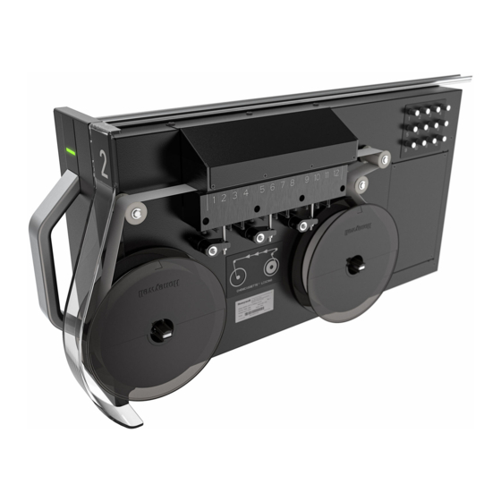
CHAPTER Introduction Analyzer side panel — Exterior Vertex Compliance System User Manual... - Page 8 1. Needle Valve for flow adjustment 2. Optics Block 3. RFID reader 4. Take-up reel 5. Tape guide roller 1. Analyzer Number Tag 2. Analyzer Status LED. 3. Analyzer Release Button Vertex Compliance System User Manual...
-
Page 9: Analyzer Side Panel - Interior
Analyzer side panel — Interior 1. Analyzer Main Board 2. Sample pressure transducers 3. Sample flow transducers Analyzer — Front view 1. Analyzer Status LED 2. Analyzer Number Tag Chemcassette Vertex Compliance System User Manual... - Page 10 Vertex Compliance System User Manual...
-
Page 11: Clean The Optics
Clean the Optics Clean Chemcassette optics annually or whenever optics verification error occurs. Compressed air is required 1. Open the Optics Block Gate. 2. Remove the Chemcassette. 3. Open the Vertex Cside panel. 4. Remove tubing (shown in photo) one at the time and blow out with compressed air. 5. -
Page 12: Additional Information
59°F to 95°F (15°C to 35°C) Humidity 20-80% RH Altitude -1000 ft. (–305 m) to 6000 ft. (1829 m) above sea level Honeywell Analytics Barclay Boulevard Lincolnshire, Illinois 60069, USA is.gas.techsupport@honeywell.com Tel: +1 847 955 8200 Toll free: +1 800 538 0363 User Manual...