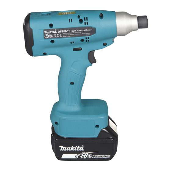
Makita DFT060T Instruction Manual
Hide thumbs
Also See for DFT060T:
- Instruction manual (100 pages) ,
- Instruction manual (125 pages) ,
- Instruction manual (101 pages)
Table of Contents
Advertisement
Quick Links
Advertisement
Table of Contents

Summary of Contents for Makita DFT060T
- Page 1 INSTRUCTION MANUAL Cordless Screwdriver DFT060T DFT120T Read before use.
-
Page 2: Specifications
The typical A-weighted noise level determined accord- for the equipment. Be sure that you understand their ing to EN62841-2-2: meaning before use. Model DFT060T Sound pressure level (L ) : 70 dB(A) or less Read instruction manual. Uncertainty (K) : 3 dB (A) -
Page 3: Ec Declaration Of Conformity
The vibration total value (tri-axial vector sum) deter- adapter plugs with earthed (grounded) power mined according to EN62841-2-2: tools. Unmodified plugs and matching outlets will Model DFT060T reduce risk of electric shock. Work mode: screwdriving without impact Avoid body contact with earthed or grounded Vibration emission (a ) : 2.5 m/s... -
Page 4: Cordless Screwdriver Safety Warnings
Do not let familiarity gained from frequent use Keep handles and grasping surfaces dry, clean of tools allow you to become complacent and and free from oil and grease. Slippery handles and ignore tool safety principles. A careless action grasping surfaces do not allow for safe handling and can cause severe injury within a fraction of a control of the tool in unexpected situations. - Page 5 Avoid storing battery cartridge in a con- also void the Makita warranty for the Makita tool and tainer with other metal objects such as charger. nails, coins, etc.
-
Page 6: Functional Description
Indicating the remaining battery capacity FUNCTIONAL DESCRIPTION Only for battery cartridges with the indicator CAUTION: Always be sure that the tool is switched off and the battery cartridge is removed before adjusting or checking function on the tool. Installing or removing battery cartridge CAUTION: Always switch off the tool before... -
Page 7: Overheat Protection
Let the tool and battery(ies) cool down. ► 1 . Lamp If no improvement can be found by restoring protection system, then contact your local Makita Service Center. NOTE: Pre-set lighting settings can be customized Switch action in application preferences. For detailed information, refer to the instruction manual supplied with the appli- cation software designed for this tool. -
Page 8: Electric Brake
This tool is equipped with an electric brake. If the tool consistently fails to quickly stop after the switch trigger is released, have the tool serviced at a Makita service center. NOTE: An electric brake function can be activated or deactivated in application preferences. - Page 9 If no improvement is found, ask your local Makita Service Center for repair. Overheat protection The motor or controller gen- The LED indicator A series Remove the battery erates excessive heat, and...
- Page 10 If the including line breaks. indicator remains lit, ask your local Makita Service Center for repair. Maintenance notice Maintenance notice will be The LED indicator Reset the mainte- posted for optimum operational flashes in yellow.
-
Page 11: Tool Settings
Archiving and sharing tool preferences through the software can enhance work performance. Connecting with computer NOTICE: Use the Makita genuine USB cable to connect the tool with your computer. Plug the USB cable into the USB port on your computer. - Page 12 Switch control on display panel and screen components Buttons and descriptions on start screen Fig.9 LED indicator A 10. Job indicator Lights up in green, red, blue and yellow colors. Displays the job number currently selected. Display screen Up to 8 jobs can be stored in the tool memory using the application software designed for this tool.
-
Page 13: Settings Menu
Settings menu The following settings menu options are available in the settings menu window. Level 1 Level 2 Level 3 Level 4 Total job settings “Total Job” menu * Not available for this tool “Manual Mode” menu Job settings Start menu (start PIN code menu Select menu screen) -
Page 14: Job Settings
Job settings Network settings Fig.12 Fig.14 ► 1 . Job number you select 2. Total job numbers Learn your device identification. stored in tool memory PIN settings Select one of the jobs previously saved in the tool memory. Button Action Application Press Change setting values. Press and hold Confirm setting History settings... -
Page 15: Installing Hook
Procedure 2 ASSEMBLY In addition to Procedure 1, insert the bit-piece into the sleeve with its pointed end facing in. CAUTION: Always be sure that the tool is switched off and the battery cartridge is removed before carrying out any work on the tool. Installing or removing driver bit/socket bit Fig.18 ► 1 . -
Page 16: Operation
Never use gasoline, benzine, thinner, alcohol or the like. Discoloration, deformation or cracks may result. To maintain product SAFETY and RELIABILITY, repairs, any other maintenance or adjustment should be performed by Makita Authorized or Factory Service Centers, always using Makita replacement parts. 16 ENGLISH... -
Page 17: Optional Accessories
OPTIONAL ACCESSORIES CAUTION: These accessories or attachments are recommended for use with your Makita tool specified in this manual. The use of any other accessories or attachments might present a risk of injury to persons. Only use accessory or attachment for its stated purpose. - Page 20 Makita Europe N.V. Jan-Baptist Vinkstraat 2, 3070 Kortenberg, Belgium Makita Corporation 3-11-8, Sumiyoshi-cho, Anjo, Aichi 446-8502 Japan 885935-220 www.makita.com 20220119...


