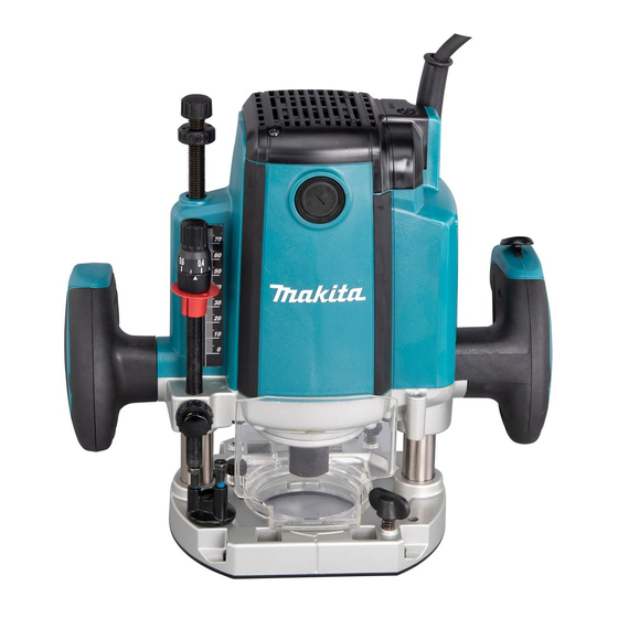
Makita RP1802 Instruction Manual
Hide thumbs
Also See for RP1802:
- Instruction manual (99 pages) ,
- Instruction manual (77 pages) ,
- Instruction manual (21 pages)
Summary of Contents for Makita RP1802
- Page 1 INSTRUCTION MANUAL Router RP1802 RP1802F RP1803 RP1803F RP2302FC RP2303FC DOUBLE INSULATION Read before use.
-
Page 2: Specifications
The followings show the symbols which may be used for the equip- The typical A-weighted noise level determined accord- ment. Be sure that you understand their meaning before use. ing to EN62841-2-17: Model RP1802 Read instruction manual. Sound pressure level (L ) : 85 dB(A) -
Page 3: Ec Declaration Of Conformity
The vibration total value (tri-axial vector sum) deter- tions for future reference. mined according to EN62841-2-17: The term "power tool" in the warnings refers to your Model RP1802 mains-operated (corded) power tool or battery-operated Work mode: cutting grooves in MDF (cordless) power tool. - Page 4 Do not expose power tools to rain or wet con- Always wear protective goggles to protect your eyes ditions. Water entering a power tool will increase from injury when using power tools.The goggles must comply with ANSI Z87.1 in the USA, EN 166 in the risk of electric shock.
-
Page 5: Router Safety Warnings
Service WARNING: DO NOT let comfort or familiarity Have your power tool serviced by a qualified with product (gained from repeated use) replace repair person using only identical replacement strict adherence to safety rules for the subject parts. This will ensure that the safety of the power product. -
Page 6: Nylon Nut
Nylon nut Switch action CAUTION: CAUTION: Do not lower the nylon nut too low. Before plugging in the tool, always The router bit will protrude dangerously. check to see that the switch trigger actuates properly and returns to the "OFF" position when released. The upper limit of the tool body can be adjusted by CAUTION: Make sure that the shaft lock is... - Page 7 Unintentional restart proof Refer to the table for the relationship between the num- ber settings on the dial and the approximate tool speed. The tool does not start with the switch trigger pulled even when the tool is plugged. Number At this time, the indication lamp blinks in red and shows 9,000 the unintentional restart proof device is on function.
-
Page 8: Operation
Insert the router bit all the way into the collet cone. Turn the tool on and wait until the router bit attains full speed. Press the shaft lock to keep the shaft stationary and use the wrench to tighten the collet nut securely. Lower the tool body and move the tool forward When using router bits with smaller shank diameter, first over the workpiece surface, keeping the base flush and... - Page 9 If the distance between the side of the workpiece and Straight guide the cutting position is too wide for the straight guide, or if the side of the workpiece is not straight, the straight The straight guide is effectively used for straight cuts guide cannot be used.
- Page 10 When set to maximum opening width Fine adjusting function for positioning blade in relation to straight guide Fig.20 Templet guide Fig.17 ► 1. Thumb screw (A) 2. Thumb screw (B) 3. Scale ring Optional accessory The templet guide provides a sleeve through which the Loosen the thumb screw (A).
- Page 11 Secure the templet to the workpiece. Place the Install the trimmer guide on the guide holder using the clamp- tool on the templet and move the tool with the templet ing screw (D). Insert the guide holder into the holes in the tool guide sliding along the side of the templet.
- Page 12 Connect a vacuum cleaner to the dust nozzle. Fig.31 ► 1. Screw M6 x 135 in a screw hole Fig.28 How to use screw M6 x 135 for adjusting the depth of cut When using the tool with a router table available in the market, using this screw allows an operator to obtain a small amount of adjustment of the depth of cut from above the table.
-
Page 13: Maintenance
CAUTION: perform inspection or maintenance. These accessories or attachments are recommended for use with your Makita tool NOTICE: Never use gasoline, benzine, thinner, specified in this manual. The use of any other alcohol or the like. Discoloration, deformation or accessories or attachments might present a risk of cracks may result. - Page 14 “V”Grooving bit Router bits Straight bit Fig.38 Unit:mm Fig.36 θ Unit:mm 1/4″ 90° Drill point flush trimming bit 1/4″ 1/2″ 1/2″ 1/4″ 1/4″ Fig.39 “U”Grooving bit Unit:mm Fig.37 Unit:mm 14 ENGLISH...
- Page 15 Drill point double flush trimming bit Corner rounding bit Fig.40 Fig.42 Unit:mm Unit:mm Board-jointing bit Chamfering bit Fig.41 Fig.43 Unit:mm Unit:mm θ 30° 45° 60° 15 ENGLISH...
- Page 16 Cove beading bit Ball bearing corner rounding bit Fig.44 Fig.46 Unit:mm Unit:mm 1/4″ Ball bearing flush trimming bit Ball bearing chamfering bit Fig.45 Fig.47 Unit:mm Unit:mm θ 1/4″ 45° 1/4″ 60° 16 ENGLISH...
- Page 17 Ball bearing beading bit Ball bearing roman ogee bit Fig.48 Fig.50 Unit:mm Unit:mm Ball bearing cove beading bit Fig.49 Unit:mm 17 ENGLISH...
- Page 20 Makita Europe N.V. Jan-Baptist Vinkstraat 2, 3070 Kortenberg, Belgium Makita Corporation 3-11-8, Sumiyoshi-cho, Anjo, Aichi 446-8502 Japan 885917A222 www.makita.com 20210622...


