Grizzly G0632 Owner's Manual
16" x 42" variable speed wood lathe
Hide thumbs
Also See for G0632:
- Owner's manual (56 pages) ,
- Parts breakdown (5 pages) ,
- Owner's manual (56 pages)
Table of Contents
Advertisement
Quick Links
MODEL G0632
16" X 42" VARIABLE SPEED
WOOD LATHE
OWNER'S MANuAL
(For models manufactured since 4/12)
Copyright © ApriL, 2007 By grizzLy industriAL, inC. revised mAy, 2012 (tr)
WARNING: NO PORTION Of THIS MANuAL MAy BE REPRODucED IN ANy SHAPE
OR fORM WITHOuT THE WRITTEN APPROVAL Of GRIzzLy INDuSTRIAL, INc.
#ts8724 printed in ChinA
Advertisement
Table of Contents

Related Manuals for Grizzly G0632


Summary of Contents for Grizzly G0632
- Page 1 OWNER'S MANuAL (For models manufactured since 4/12) Copyright © ApriL, 2007 By grizzLy industriAL, inC. revised mAy, 2012 (tr) WARNING: NO PORTION Of THIS MANuAL MAy BE REPRODucED IN ANy SHAPE OR fORM WITHOuT THE WRITTEN APPROVAL Of GRIzzLy INDuSTRIAL, INc.
- Page 2 This manual provides critical safety instructions on the proper setup, operation, maintenance, and service of this machine/tool. Save this document, refer to it often, and use it to instruct other operators. Failure to read, understand and follow the instructions in this manual may result in fire or serious personal injury—including amputation, electrocution, or death.
-
Page 3: Table Of Contents
Table of contents INTRODucTION ..........2 SEcTION 5: AccESSORIES ......37 manual Accuracy ........... 2 SEcTION 6: MAINTENANcE ......38 Contact info............ 2 schedule ............38 machine description ........2 Cleaning ............38 identification ........... 3 Lathe Bed............. 38 glossary of terms ......... 5 Lubrication ........... -
Page 4: Introduction
Email: manuals@grizzly.com Machine Description Manufacture Date of Your Machine the g0632 16" X 42" Wood Lathe is designed to turn wood stock so the operator can remove material with a chisel. the variable speed control allows for spindle speed adjustment from 100–3200 rpm and the... -
Page 5: Identification
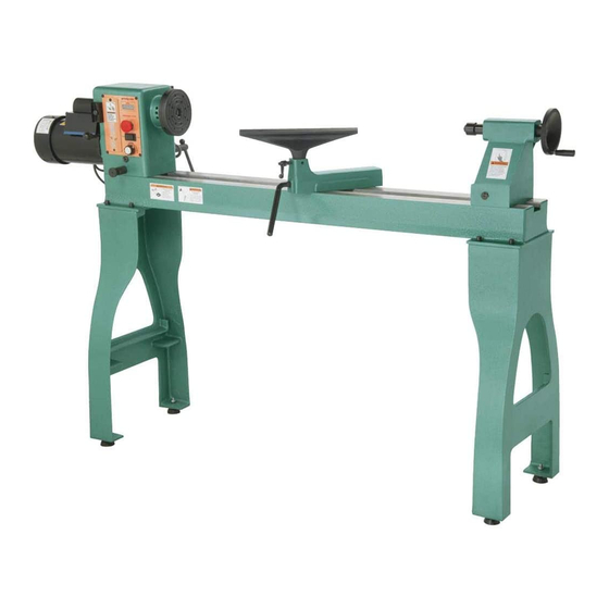
Control tool rest Base panel Lock handle tool rest Base Lock handle supporting Leg figure 1. model g0632 component identification. To reduce the risk of serious injury when using this machine, read and understand this entire manual before beginning any operations. - Page 6 Opening the frequency inverter will void the lathe warranty and could seriously damage the lathe. DO NOT open the case of the frequency inverter. spindle direction variable switch speed dial figure 3. model g0632 control panel identification. Model G0632 (Mfg. 4/12+)
-
Page 7: Glossary Of Terms
Offset Turning: A turning situation where the cen- ter of the workpiece is offset at various stages Way: one of the metal rails that make up the bed of the work to produce different shapes. of the lathe. Model G0632 (Mfg. 4/12+) -
Page 8: Machine Data Sheet
MACHINE DATA SHEET Customer Service #: (570) 546-9663 · To Order Call: (800) 523-4777 · Fax #: (800) 438-5901 MODEL G0632 16" X 42" VARIABLE SPEED WOOD LATHE Product Dimensions: Weight................................386 lbs. Width (side-to-side) x Depth (front-to-back) x Height............77-1/16 x 22-1/16 x 47 in. - Page 9 The information contained herein is deemed accurate as of 7/22/2013 and represents our most recent product specifications. Model G0632 PAGE 2 OF 3 Due to our ongoing improvement efforts, this information may not accurately describe items previously purchased. Model G0632 (Mfg. 4/12+)
-
Page 10: Section 1: Safety
Everyday ery. Never operate under the influence of drugs or eyeglasses are not approved safety glasses. alcohol, when tired, or when distracted. Model G0632 (Mfg. 4/12+) - Page 11 ChILdREN & BYsTANdERs. Keepchildrenand cord/plugwithwethands.Avoidcorddamageby bystandersatasafedistancefromtheworkarea. keepingitawayfromheatedsurfaces,hightraffic Stopusingmachineiftheybecomeadistraction. areas,harshchemicals,andwet/damplocations. GuARds & COVERs.Guardsandcoversreduce EXPERIENCING dIFFICuLTIEs. If at any time accidental contact with moving parts or flying youexperiencedifficultiesperformingtheintend- debris. Make sure they are properly installed, edoperation,stopusingthemachine!Contactour undamaged,andworkingcorrectly. TechnicalSupportat(570)546-9663. Model G0632 (Mfg. 4/12+)
-
Page 12: Additional Safety For Wood Lathes
If normal safety precautions are overlooked or ignored, seri- sonal injury, damage to equipment, or poor work results. ous personal injury may occur. -10- Model G0632 (Mfg. 4/12+) -
Page 13: Section 2: Power Supply
To reduce the risk of these hazards, avoid over- loading the machine during operation and make sure it is connected to a power supply circuit that meets the requirements in the following section. -11- Model G0632 (Mfg. 4/12+) -
Page 14: Grounding Requirements
Maximum Length (Shorter is Better)..50 ft. is properly installed and grounded in accordance with all local codes and ordinances. GROUNDED 6-15 RECEPTACLE Current Carrying Prongs 6-15 PLUG Grounding Prong figure 4. typical 6-15 plug and receptacle. -12- Model G0632 (Mfg. 4/12+) -
Page 15: Section 3: Setup
(for each person) ....1 • Cleaner/degreaser (Page 15) ..As needed • disposable shop rags ....As needed • measuring tape ......... 1 • Wrench 17mm ..........1 • Level ............1 -13- Model G0632 (Mfg. 4/12+) -
Page 16: Inventory
Box Inventory: (figures 5–7) A. Lathe Assembly figure 6. model g0632 inventory B. —headstock (mounted) ......1 —tool rest Base (mounted) ...... 1 —tailstock (mounted) ........ 1 —Face plate 6"... -
Page 17: Cleanup
Repeat Steps 2–3 as necessary until clean, figure 8. t23692 orange power degreaser. then coat all unpainted surfaces with a quality metal protectant to prevent rust. -15- Model G0632 (Mfg. 4/12+) -
Page 18: Site Considerations
Shadows, glare, or strobe effects that may distract access restricted location. or impede the operator must be eliminated. 220V, Single-Phase * Footprint ‡ Minimum Working Clearance Motor * 60" ‡ 77 " figure 9. minimum working clearances. -16- Model G0632 (Mfg. 4/12+) -
Page 19: Mounting To Shop Floor
11. stand legs approximately 47" apart to prepare for mounting the lathe. Anchor studs The G0632 and its com- ponents are very heavy. Get lifting help or use power lifting equipment Lag shield Anchor... - Page 20 Base Note: Use assistants to support and stabilize Lock Lever the lathe while you install the machine feet. figure 15. tool rest installed on the tool rest base. -18- Model G0632 (Mfg. 4/12+)
-
Page 21: Power Connection
Power 1. Turn the machine power switch OFF. 2. Insert the power cord plug into a matching power supply receptacle. The machine is now connected to the power source. figure 17. Disconnecting power. figure 16. Connecting power. -19- Model G0632 (Mfg. 4/12+) -
Page 22: Test Run
Call tech support for help. -20- Model G0632 (Mfg. 4/12+) -
Page 23: Section 4: Operations
Regardless of the content in this section, positions any dust collection hoods near the Grizzly Industrial will not be held liable for workpiece to collect wood chips and secures accidents caused by lack of training. -
Page 24: Basic Controls
360°. ties back loose hair and clothing, and puts To position the headstock along the length of on face shield and respirator. -
Page 25: Adjusting Tailstock
Otherwise, serious pressure as needed. personal injury may occur. Always operate the lathe with the tailstock firmly locked to the bed. Otherwise, serious personal injury may occur. -23- Model G0632 (Mfg. 4/12+) -
Page 26: Adjusting Tool Rest
Turn this hex nut in small increments to fine tune the clamping pressure as needed. -24- Model G0632 (Mfg. 4/12+) -
Page 27: Installing/Removing Headstock Center
26. removing the headstock center. insert the tapered end of the center into the spindle, and push it in with a quick, firm motion (see figure 25). figure 25. installing center into the headstock spindle. -25- Model G0632 (Mfg. 4/12+) -
Page 28: Installing/Removing Tailstock Center
(see figure 28) to ensure that the tailstock center and quill will not freely rotate under load. -26- Model G0632 (Mfg. 4/12+) -
Page 29: Headstock Faceplate
29. depressing the spindle lock. nect the lathe from the power source and perform maintain pressure on the spindle lock and the steps above in reverse. thread the faceplate onto the spindle until it is snug. -27- Model G0632 (Mfg. 4/12+) -
Page 30: Changing Speed Ranges
LAthe From the poWer sourCe! remove the front belt access panel (see the model g0632 has two speed ranges: 1) the figure 32). low range from 100 to 1200 rpm which provides a greater torque, and 2) the high range from 250 to 3200 rpm. - Page 31 As a general rule, the larger the workpiece diameter, the slow- er the speed. Always start the lathe on slow speed. failure to heed this warning could lead to serious personal injury. -29- Model G0632 (Mfg. 4/12+)
-
Page 32: Indexing
By inserting the indexing pin into one of the three outer indexes of the model g0632 spindle hous- ing and engaging one of the twelve inner indexes in the spindle, the workpiece can be positioned to one of 36 equal points (see figure 36). -
Page 33: Selecting Turning Tools
(usually at an angle of 20°–40°). figure 41. example of a parting tool. Specialty Tools—these are the unique, • special function tools to aid in hollowing, bowl making, cutting profiles, etc. figure 39. example of a skew chisel. -31- Model G0632 (Mfg. 4/12+) -
Page 34: Spindle Turning
Damage to your eyes and lungs could result from using this machine without proper pro- tective gear. Always wear a face shield and respirator when operating this machine. -32- Model G0632 (Mfg. 4/12+) - Page 35 (refer to Installing Headstock center on Page 25 for additional instructions). Note: Use the tool rest to support the opposite end of the workpiece so that the workpiece and spur center do not separate. -33- Model G0632 (Mfg. 4/12+)
- Page 36 Damage to your eyes and lungs could result serious personal injury. from using this machine without proper pro- tective gear. Always wear a face shield and respirator when operating this machine. -34- Model G0632 (Mfg. 4/12+)
-
Page 37: Faceplate Turning
Note: Allow the glue to cure according to the manufacturer's instructions. figure 47. typical attachment of faceplate to workpiece (shown with backing block). -35- Model G0632 (Mfg. 4/12+) -
Page 38: Outboard Turning
Otherwise, the spinning workpiece could or finishing materials Workpiece force the lathe tool out of your hands or completely around the entangle your hands into the workpiece. workpiece. failure to heed this warning could result in serious personal injury. -36- Model G0632 (Mfg. 4/12+) -
Page 39: Section 5: Accessories
52. model g1082 4-Jaw Chuck. figure 54. robert sorby stebcentre. G3167—1 ⁄ " x 8 TPI RH Threaded Insert this threaded insert is required to mount a 3- or 4-jaw chuck to your wood lathe. -37- Model G0632 (Mfg. 4/12+) -
Page 40: Section 6: Maintenance
For optimum performance from your machine, follow this maintenance schedule and refer to any specific instructions given in this section. All bearings for the model g0632 are lubricated Daily check: and sealed at the factory, and do not need addi- •... -
Page 41: Section 7: Service
7. Workpiece, center, or faceplate is at fault. 7. Center workpiece in center or faceplate; reduce rpm; replace defective center or faceplate. 8. motor bearings are at fault. 8. test by rotating shaft; rotational grinding/loose shaft requires bearing replacement. -39- Model G0632 (Mfg. 4/12+) -
Page 42: Wood Lathe Operation
1. turn the barrel handwheel until it forces taper out of from tailstock barrel. the way back into the tailstock. barrel. 2. debris was not removed from taper Always make sure that taper surfaces are clean. before inserting into barrel. -40- Model G0632 (Mfg. 4/12+) -
Page 43: Aligning Centers
Note: When properly tensioned, the belt set screws in the spindle handwheel and should deflect about ⁄ " when moderate pres- remove it from the spindle. sure is applied to the belt mid-way between the upper and lower pulley. -41- Model G0632 (Mfg. 4/12+) -
Page 44: Section 8: Wiring
Technical source. Support at (570) 546-9663. The photos and diagrams included in this section are best viewed in color. You can view these pages in color at www.grizzly.com. -42- Model G0632 (Mfg. 4/12+) -
Page 45: Electrical Components
Button Control rpm readout & Circuit Board figure 58. model g0632 control panel wiring figure 60. model g0632 rpm sensor wiring. (shown from the back of the panel). figure 59. model g0632 motor junction box figure 61. model g0632 frequency inverter wiring. -
Page 46: Wiring Diagram Overview
(figure 58, Page 43) RPM Sensor (figure 60, Page 43) Variable Speed REV/FWD Emergency RPM Readout Control Switch Stop & Circuit Board View this page in color at www.grizzly.com. READ ELECTRICAL SAFETY -44- Model G0632 (Mfg. Since 1/09+) ON PAGE 42! -
Page 47: Frequency Inverter Wiring Diagram
Inverter Wiring Diagram 220V, 1-Phase Ground Frequency 6-15 Plug (As Recommended) Inverter +10V AVI AFM M0 M5 GND View this page in color at www.grizzly.com. To Controls To Motor READ ELECTRICAL SAFETY -45- Model G0632 (Mfg. Since 1/09+) ON PAGE 42! -
Page 48: Section 9: Parts
SEcTION 9: PARTS Stand Breakdown 20-1 -46- Model G0632 (Mfg. 4/12+) -
Page 49: Stand Parts List
P0632010 TOOL REST BASE LOCK HANDLE P0632025 CLAMP P0632011 LIVE CENTER PN29M HEX NUT M18-2.5 P0632012 QUILL PN02M HEX NUT M10-1.5 P0632013 TAILSTOCK LOCK BRACKET P0632028 MACHINE FOOT P0632014 BUSHING P0632029 HANDWHEEL HANDLE P0632015 LEADSCREW -47- Model G0632 (Mfg. 4/12+) -
Page 50: Headstock Breakdown
Headstock Breakdown -48- Model G0632 (Mfg. 4/12+) -
Page 51: Headstock Parts List
COMPRESSION SPRING 61-4 P0632061-4 FAN COVER P0632106 ROTATION LOCK PIN NUT 61-5 P0632061-5 P0632107 COMPRESSION SPRING 61-6 P0632061-6 MOTOR JUNCTION BOX PR39M EXT RETAINING RING 8MM 61-7 P0632061-7 JUNCTION BLOCK PSS31M SET SCREW M5-.8 X 8 -49- Model G0632 (Mfg. 4/12+) -
Page 52: Label Placement
MuST maintain the original location and readability of the labels on the machine. If any label is removed or becomes unreadable, REPLAcE that label before using the machine again. contact Grizzly at (800) 523-4777 or www.grizzly.com to order new labels. -50- Model G0632 (Mfg. 4/12+) -
Page 53: Warranty And Returns
WARRANTy AND RETuRNS grizzly industrial, inc. warrants every product it sells for a period of 1 year to the original purchaser from the date of purchase. this warranty does not apply to defects due directly or indirectly to misuse, abuse, negligence, accidents, repairs or alterations or lack of maintenance. -
Page 54: Warranty Card
Do you think your machine represents a good value? _____ Yes _____No Would you recommend Grizzly Industrial to a friend? _____ Yes _____No Would you allow us to use your name as a reference for Grizzly customers in your area? Note: We never use names more than 3 times. - Page 55 FOLD ALONG DOTTED LINE Place Stamp Here GRIZZLY INDUSTRIAL, INC. P.O. BOX 2069 BELLINGHAM, WA 98227-2069 FOLD ALONG DOTTED LINE Send a Grizzly Catalog to a friend: Name_______________________________ Street_______________________________ City______________State______Zip______ TAPE ALONG EDGES--PLEASE DO NOT STAPLE...