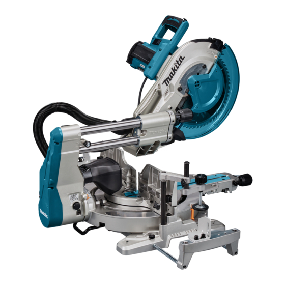
Makita LS1219 Instruction Manual
Slide compound miter saw
Hide thumbs
Also See for LS1219:
- Instruction manual (193 pages) ,
- Instruction manual (33 pages) ,
- Instruction manual (105 pages)

Related Manuals for Makita LS1219


Summary of Contents for Makita LS1219
- Page 1 INSTRUCTION MANUAL Slide Compound Miter Saw LS1219 LS1219L DOUBLE INSULATION Read before use.
-
Page 2: Specifications
SPECIFICATIONS Model: LS1219 LS1219L Blade diameter 305 mm Hole diameter European countries 30 mm Countries other than Europe 25.4 mm or 30 mm (country specific) Max. kerf thickness of the saw blade 3.2 mm Max. miter angle Right 60°, Left 60°... -
Page 3: Power Supply
Never look into the laser beam. Direct laser The vibration total value (tri-axial vector sum) deter- beam may injure your eyes. mined according to EN62841-3-9: Model LS1219 Do not install the horizontal vise to the same direction as the miter cutting. (This Vibration emission (a ) : 2.5 m/s... -
Page 4: General Power Tool Safety Warnings
Personal safety SAFETY WARNINGS Stay alert, watch what you are doing and use common sense when operating a power tool. Do not use a power tool while you are tired or General power tool safety warnings under the influence of drugs, alcohol or med- ication. -
Page 5: Safety Instructions For Mitre Saws
Power tool use and care The workpiece must be stationary and clamped or held against both the fence and the Do not force the power tool. Use the correct table. Do not feed the workpiece into the blade power tool for your application. The correct or cut "freehand"... - Page 6 Plan your work. Every time you change the bevel Additional instructions or mitre angle setting, make sure the adjustable Make workshop kid proof with padlocks. fence is set correctly to support the workpiece Never stand on the tool. Serious injury could and will not interfere with the blade or the guard- occur if the tool is tipped or if the cutting tool is ing system.
-
Page 7: Parts Description
19. Stop operation immediately if you notice any- Additional safety rules for the laser thing abnormal. LASER RADIATION, DO NOT STARE INTO THE 20. Do not attempt to lock the trigger in the "ON" BEAM OR VIEW DIRECTLY WITH OPTICAL position. -
Page 8: Installation
Switch trigger Lock-off button Hole for padlock Switch (for laser line) Hose (for dust Stopper pin (for carriage Guide fence (lower Guide fence (upper extraction) elevation) fence) fence) Dust bag 0° adjusting bolt (for Bevel angle scale Releasing lever (for 48° bevel angle) bevel angle) Latch lever (for bevel... -
Page 9: Bench Mounting
Installing the dust extraction hose Bench mounting Connect the dust extraction hose to the tool as When the tool is shipped, the handle is locked in the illustrated. lowered position by the stopper pin. While lowering the Make sure that the elbow and the sleeve fit properly to handle slightly, pull the stopper pin and rotate it 90°. -
Page 10: Functional Description
When cleaning is complete, reverse proce- dure above and secure bolt. Do not remove spring holding blade guard. If guard becomes discolored through age or UV light exposure, contact a Makita service center for a new guard. DO NOT DEFEAT OR REMOVE GUARD. 10 ENGLISH... - Page 11 Push the carriage toward the guide fence fully and lower the handle completely. Adjust the blade position by turning the adjusting bolt with the hex wrench. The periphery of the blade should extend slightly below the top surface of the turn base and also comes to the point where the front face of the guide fence meets the top surface of the turn base.
-
Page 12: Adjusting The Miter Angle
Adjusting the miter angle WARNING: After installing a new blade and with the tool unplugged, always be sure that the blade does not contact any part of the lower base CAUTION: After changing the miter angle, when the handle is lowered completely. If a blade always secure the turn base by tightening the grip makes contact with the base it may cause kickback firmly. -
Page 13: Adjusting The Bevel Angle
Match the pointer with your desired angle on the Adjusting the bevel angle scale by moving the carriage then tighten the knob. NOTICE: Always remove the upper guide fences and vertical vise before adjusting the bevel angle. NOTICE: When changing bevel angles, be sure to position the kerf boards appropriately as explained in the "Kerf boards"... -
Page 14: Slide Lock
A switch in need of repair may result in unintentional operation and serious personal injury. Return tool to a Makita service center for proper repairs BEFORE further usage. ► 1. Switch trigger 2. Lock-off button 3. Hole for padlock... -
Page 15: Electronic Function
To prevent the switch trigger from being accidentally Laser line can be shifted to either the left or right side of pulled, a lock-off button is provided. To start the tool, the saw blade by turning the adjusting screw as follows. press in the lock-off button and pull the switch trigger. -
Page 16: Removing And Installing Saw Blade
Accidental start up of the tool may result in serious personal injury. WARNING: Use only the Makita wrench pro- vided to install or remove the blade. Failure to use the wrench may result in overtightening or insufficient tightening of the hex socket bolt and serious personal injury. -
Page 17: Installing The Blade
Connecting a vacuum cleaner When you wish to perform clean cutting operation, con- nect a Makita vacuum cleaner to the dust nozzle using a front cuff 24 (optional accessory). ► 1. Arrow on the blade case 2. Arrow on the blade ►... -
Page 18: Securing Workpiece
Dust bag Securing workpiece The use of the dust bag makes cutting operations clean WARNING: It is extremely important to always and dust collection easy. To attach the dust bag, remove secure the workpiece correctly with the proper the dust extraction hose from the tool and connect the type of vise or crown molding stoppers. - Page 19 Use upper fences to support the material higher than Vertical vise the lower fences. Insert the upper fence into the hole on the lower fence and tighten the clamping screw. WARNING: The workpiece must be secured firmly against the turn base and guide fence with the vise during all operations.
- Page 20 Sub base NOTE: For a quick setting of workpiece, turning the vise knob to 90° counterclockwise allows the vise knob to be moved up and down. To secure the work- WARNING: Always support a long workpiece piece after setting, turn the vise knob clockwise. so it is level with the top surface of the turn base for an accurate cut and to prevent dangerous loss Horizontal vise...
-
Page 21: Operation
— Aluminum products Refer to our website or contact your local Makita dealer Workpieces up to 92 mm high and 183 mm wide can be for the correct circular saw blades to be used for the cut in the following manner. -
Page 22: Bevel Cut
Bevel cut WARNING: After setting the blade for a bevel cut, ensure that the carriage and saw blade will have free travel throughout the entire range of the intended cut before operating the tool. Interruption of the carriage or blade travel during the cutting oper- ation may result in kickback and serious personal injury. -
Page 23: Compound Cutting
Compound cutting Cutting crown and cove moldings Compound cutting is the process in which a bevel Crown and cove moldings can be cut on a compound angle is made at the same time in which a miter angle miter saw with the moldings laid flat on the turn base. is being cut on a workpiece. - Page 24 Measuring Table (B) – Molding Molding Finished Measure the wall width, and adjust the width of the position in edge against piece workpiece according to it. Always make sure that width the figure guide fence of the workpiece's wall contact edge is the same as wall length.
- Page 25 Table (B) At left 45° miter angle – Molding Molding Finished position in edge against piece the figure guide fence For inside Wall contact Finished corner edge should piece will be be against on the Right guide fence. side of blade. Ceiling contact edge For outside...
-
Page 26: Groove Cutting
Table (C) CAUTION: Use straight wood of even thick- – Molding Miter angle Finished ness for the wood facing. position in piece CAUTION: In order to completely cut through the figure workpieces with a height of 107 mm to 120 mm, a For inside Right 45°... - Page 27 For a dado type cut, perform as follows: WARNING: Be sure to use flat stock as a Adjust the lower limit position of the saw blade platform. Stock that is not flat may move during the using the adjusting screw and the stopper arm to limit cutting operation which may result in kickback and the cutting depth of the saw blade.
-
Page 28: Maintenance
Secure the workpiece firmly against the upper WARNING: Stopper pin for carriage elevation fences with a vise before cutting. is for carrying and storage purposes only and not for any cutting operations. The use of the stopper pin for cutting operations may cause unexpected movement of the saw blade resulting in kickback and serious personal injury. -
Page 29: Bevel Angle
Set the turn base to the 0° position using the positive Carefully square the side of the saw blade with the top stop function. Square the side of the blade with the face surface of the turn base using the triangular rule, try- of the guide fence using a triangular rule or try-square. - Page 30 NOTICE: Have the tool repaired by a Makita authorized service center for any failure on the laser unit. The movable range of laser line is decided by the range adjustment screws on both sides.
-
Page 31: Replacing Carbon Brushes
Adjusting the laser line on the left side of the blade Cleaning the laser light lens For model LS1219L only The laser light becomes hard to see as the lens for the laser light gets dirty. Clean the lens for laser light periodically. -
Page 32: After Use
• Dust bag releasing the switch trigger. If the electric brake is not working • Triangular rule correctly, have the tool repaired by a Makita service center. • Hex wrench After use • Hex wrench (for LS1219L)