
Related Manuals for Makita LS1219/1


Summary of Contents for Makita LS1219/1
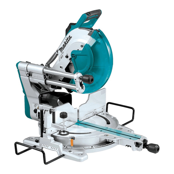
- Page 1 INSTRUCTION MANUAL Slide Compound Miter Saw LS1219 LS1219L DOUBLE INSULATION Read before use.
-
Page 2: Specifications
SPECIFICATIONS Model: LS1219 LS1219L Blade diameter 305 mm Hole diameter European countries 30 mm Countries other than Europe 25.4 mm Max. kerf thickness of the saw blade 3.2 mm Max. miter angle Right 60°, Left 60° Max. bevel angle Right 48°, Left 48° No load speed (RPM) 3,200 min Laser type... -
Page 3: Power Supply
Do not place hand or fingers close to the WARNING: The vibration emission during actual blade. use of the power tool can differ from the declared emission value depending on the ways in which the tool is used. Never look into the laser beam. Direct laser beam may injure your eyes. WARNING: Be sure to identify safety measures to protect the operator that are based on an estima- Only for EU countries... - Page 4 When operating a power tool outdoors, use an extension cord suitable for outdoor use. Use of a cord suitable for outdoor use reduces the risk of electric shock. If operating a power tool in a damp location is unavoidable, use a residual current device (RCD) protected supply.
-
Page 5: Safety Instructions For Mitre Saws
Service Do not reach behind the fence with either hand closer than 100 mm from either side of the saw Have your power tool serviced by a qualified blade, to remove wood scraps, or for any other repair person using only identical replacement reason while the blade is spinning. - Page 6 10. While making a slide cut, KICKBACK can 17. If the workpiece or blade becomes jammed, turn the mitre saw off. Wait for all moving occur. KICKBACK occurs when the blade parts to stop and disconnect the plug from binds in the workpiece during a cutting oper- the power source and/or remove the battery ation and the saw blade is driven rapidly pack.
-
Page 7: Parts Description
PARTS DESCRIPTION Slide pole Stopper pin (for carriage Vertical vise Releasing button (for sliding) right side bevel angle) Holder Turn base Pointer (for miter angle) Miter angle scale Kerf board Blade case Adjusting screw (for Range adjustment screw laser line) (for laser line) Blade guard Knob (for bevel angle) Hex wrench Adjusting screw (for... -
Page 8: Installation
Switch trigger Lock-off button Hole for padlock Switch (for laser line) Hose (for dust Stopper pin (for carriage Guide fence (lower Guide fence (upper extraction) elevation) fence) fence) Dust bag 0° adjusting bolt (for Bevel angle scale Releasing lever (for 48° bevel angle) bevel angle) Latch lever (for bevel Pointer (for bevel angle) -
Page 9: Bench Mounting
Do not remove spring holding blade guard. If guard becomes discolored through age or UV light exposure, contact a Makita service center for a new guard. DO NOT DEFEAT OR REMOVE GUARD. 9 ENGLISH... - Page 10 ► 1 . Left bevel cut 2. Straight cut 3. Right bevel cut 4. Saw blade 5. Blade teeth 6. Kerf board First, unplug the tool. Loosen all the screws (2 each on left and right) securing the kerf boards until the kerf boards can still be easily moved by hand.
-
Page 11: Adjusting The Miter Angle
Push the carriage toward the guide fence fully and With the tool unplugged, rotate the blade by hand while lower the handle completely. holding the handle all the way down to be sure that Adjust the blade position by turning the adjusting bolt the blade does not contact any part of the lower base. with the hex wrench. -
Page 12: Adjusting The Bevel Angle
► 1 . Knob Pull and turn the latch lever to the position as illustrated. ► 1 . Lock lever 2. Grip 3. Releasing lever 4. Pointer Rotate the grip counterclockwise to unlock the turn base. Turn the grip while holding down the lock lever to move the turn base. -
Page 13: Slide Lock
► 1 . Releasing lever This miter saw employs positive stop function. You can set 22.5° and 33.9° angle to both right and left quickly. Set the latch lever in the position as illustrated and tilt the carriage. To change the angle, pull the latch lever and tilt the carriage. -
Page 14: Switch Action
(0) of the switch. ing the lock-off button. A switch in need of repair may result in unintentional operation and serious personal injury. Return tool to a Makita service center for proper repairs BEFORE further usage. ► 1 . Switch for laser Laser line can be shifted to either the left or right side of the saw blade by turning the adjusting screw as follows. -
Page 15: Removing And Installing Saw Blade
Accidental start up of the tool may result in serious personal injury. WARNING: Use only the Makita wrench pro- vided to install or remove the blade. Failure to use the wrench may result in overtightening or insufficient tightening of the hex socket bolt and serious personal injury. -
Page 16: Removing The Blade
Removing the blade Installing the blade Loosen the hex bolt holding the center cover using the Mount the blade carefully onto the spindle, making hex wrench. Raise the blade guard and center cover. sure that the direction of the arrow on the surface of the blade matches the direction of the arrow on the blade case. -
Page 17: Securing Workpiece
Connecting a vacuum cleaner When you wish to perform clean cutting operation, con- nect a Makita vacuum cleaner to the dust nozzle using a front cuff 24 (optional accessory). ► 1 . Fastener Securing workpiece WARNING: It is extremely important to always ► 1 . - Page 18 Guide fences WARNING: Before operating the tool, make sure that the upper fence is secured firmly. WARNING: Before bevel-cutting, make sure that no part of the tool, especially the blade, con- tacts the upper and lower fences when fully low- ering and raising the handle in any position and while moving the carriage through its full range of travel.
-
Page 19: Operation
Horizontal vise Optional accessory WARNING: Always rotate the vise nut clock- wise until the workpiece is properly secured. If the workpiece is not properly secured the material may move during the cutting operation causing possible damage to the blade, causing the material to be thrown and loss of control resulting in serious personal injury. -
Page 20: Miter Cutting
Press cutting WARNING: Always lock the sliding movement of the carriage when performing a press cutting. Cutting without lock may cause possible kickback which may result in serious personal injury. Workpieces up to 92 mm high and 183 mm wide can be cut in the following manner. ► 1 . -
Page 21: Bevel Cut
Bevel cut Compound cutting Compound cutting is the process in which a bevel WARNING: After setting the blade for a bevel angle is made at the same time in which a miter angle cut, ensure that the carriage and blade will have is being cut on a workpiece. - Page 22 Measuring Cutting crown and cove moldings Measure the wall width, and adjust the width of the Crown and cove moldings can be cut on a compound workpiece according to it. Always make sure that width miter saw with the moldings laid flat on the turn base. of the workpiece's wall contact edge is the same as wall There are two common types of crown moldings and length.
- Page 23 Table (B) Table (B) – Molding Molding Finished – Molding Molding Finished position in edge against piece position in edge against piece the figure guide fence the figure guide fence For inside Ceiling Finished For inside Wall contact Finished corner contact edge piece will be corner...
- Page 24 At left 45° miter angle Table (C) – Molding Miter angle Finished position in piece the figure For inside Right 45° Save the right corner side of blade Left 45° Save the left side of blade For outside Save the right corner side of blade Right 45°...
-
Page 25: Groove Cutting
For a dado type cut, perform as follows: CAUTION: Use straight wood of even thick- Adjust the lower limit position of the blade using ness for the wood facing. the adjusting screw and the stopper arm to limit the cut- CAUTION: In order to completely cut through ting depth of the blade. Refer to "Stopper arm" section workpieces with a height of 107 mm to 120 mm, a described on previously. -
Page 26: Carrying Tool
WARNING: Be sure to use flat stock as a platform. Stock that is not flat may move during the cutting operation which may result in kickback and serious personal injury. NOTE: The maximum cutting capacity in height will be reduced by the same amount as the platform thickness. Place the platform on the tool so that it extends equally over each side of the tool base. -
Page 27: Maintenance
Set the turn base to the 0° position using the positive WARNING: Stopper pin for carriage elevation stop function. Square the side of the blade with the face is for carrying and storage purposes only and not of the guide fence using a triangular rule or try-square. for any cutting operations. - Page 28 NOTICE: Have the tool repaired by a Makita If the pointer does not indicate the 45° position, align authorized service center for any failure on the it with 45° position by turning the adjusting bolt on the...
-
Page 29: Replacing Carbon Brushes
Plug in the tool and turn on the laser switch. Slide the adjusting screw to the position that the laser line comes onto the cutting line and then tighten. Loosen the adjusting screw. To move the laser line away from the blade, turn the range adjustment screws NOTE: The movable range of laser line is factory counterclockwise. To move the laser line close to the adjusted within 1 mm from the side surface of blade. -
Page 30: After Use
OPTIONAL ACCESSORIES WARNING: These Makita accessories or attachments are recommended for use with your Makita tool specified in this manual. The use of any other accessories or attachments may result in serious personal injury. WARNING: Only use the Makita accessory or attachment for its stated purpose. Misuse of an accessory or attachment may result in serious personal injury. - Page 32 Makita Europe N.V. Jan-Baptist Vinkstraat 2, 3070 Kortenberg, Belgium Makita Corporation 3-11-8, Sumiyoshi-cho, Anjo, Aichi 446-8502 Japan 885618-222 www.makita.com 20170810...