Makita LS1214 Instruction Manual
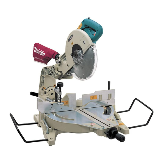
Slide compound saw
Hide thumbs
Also See for LS1214:
- Instruction manual (144 pages) ,
- Parts breakdown (5 pages) ,
- Instruction manual (60 pages)

Related Manuals for Makita LS1214


Summary of Contents for Makita LS1214
- Page 1 INSTRUCTION MANUAL Slide Compound Saw LS1214 LS1214F LS1214L 005689 DOUBLE INSULATION WARNING: For your personal safety, READ and UNDERSTAND before using. SAVE THESE INSTRUCTIONS FOR FUTURE REFERENCE.
-
Page 2: Specifications
Red Laser 650 nm, 1mW ( Laser Class 2 ) Dimensions (L x W x H) LS1214/LS1214F 723 mm x 520 mm x 696 mm LS1214L 723 mm x 520 mm x 718 mm Net weight LS1214 24.4 kg, LS1214F 24.6 kg, LS1214L 25.3 kg Safety class •... - Page 3 ・ Only for EU countries Use the right tool. Do not dispose of electric equipment Do not force small tools or attachments to do the together with household waste material! job of a heavy duty tool. Do not use tools for In observance of European Directive purposes not intended;...
-
Page 4: Additional Safety Rules For Tool
that is damaged should be carefully checked to 10. Do not use the tool in the presence of flammable determine that it will operate properly and perform liquids or gases. its intended function. Check for alignment of Check the blade carefully for cracks or damage moving parts, free running of moving parts, before operation. -
Page 5: Installation
When cleaning is complete, reverse procedure above and secure bolt. Do not remove spring holding blade guard. If guard becomes discolored through age or UV light exposure, contact a Makita service center for a new guard. DO NOT DEFEAT OR REMOVE GUARD. 001531... - Page 6 carriage toward the guide fence fully and adjust the kerf 1. Blade guard boards so that the kerf boards just contact the sides of blade teeth. Tighten the rear screws (do not tighten firmly). After adjusting the kerf boards, release the stopper pin and raise the handle.
-
Page 7: Adjusting The Miter Angle
Always do this with the tool unplugged. 1. Lever Stopper arm 1. Adjusting screw 2. Stopper arm 004056 Tilt the saw blade until the pointer points to the desired 001562 angle on the bevel scale. Then tighten the lever clockwise firmly to secure the arm. The lower limit position of the blade can be easily 1. - Page 8 • simply pull the switch trigger without pressing the Be careful not to scratch the lens of light, or it may lock-off button. Return tool to a Makita service lower the illumination. center for proper repairs BEFORE further usage. Laser beam action NEVER tape down or defeat purpose and function •...
- Page 9 • unplugged before installing or removing the blade. Laser line can be shifted to either the left or right side of Use only the Makita socket wrench provided to • the blade according to the applications of cutting. Refer install or remove the blade. Failure to do so may to explanation titled "Laser beam action"...
- Page 10 sure shaft lock has released spindle before making cut. 1. Blade case 2. Arrow 1. Center cover 3. Shaft lock 2. Hex bolt 4. Hex bolt 3. Socket wrench 5. Socket wrench 4. Blade guard 002020 002019 To install the blade, mount it carefully onto the spindle, Dust bag (accessory) making sure that the direction of the arrow on the surface of the blade matches the direction of the arrow...
-
Page 11: Securing Workpiece
1. Support 2. Turn base NOTE: If you connect a Makita vacuum cleaner to this tool, • more efficient and cleaner operations can be performed. CAUTION: Empty the dust box before collected sawdust level • reaches the cylinder part. - Page 12 The sub-fence R can be installed on the right side of the CAUTION: guide fence. Insert the rods of the sub-fence R into the The workpiece must be secured firmly against the • holes in the guide fence. Tighten the screws which come turn base and guide fence with the vise during all with the sub-fence R to secure the sub-fence R.
-
Page 13: Operation
Holders 1. Holder 005598 001544 OPERATION The holders can be installed on either side as a convenient means of holding workpieces horizontally. CAUTION: Slip the holder rods into the holes in the base and adjust Before use, be sure to release the handle from the •... - Page 14 completed, switch off the tool and WAIT UNTIL Miter cutting THE BLADE HAS COME TO A COMPLETE STOP Refer to the previously covered "Adjusting the before returning the blade to its fully elevated miter angle". position. Bevel cut CAUTION: Firmly tighten the knob clockwise so that the •...
- Page 15 table. Wood facing Use of wood facing helps to assure splinter-free Miter angle Bevel angle cuts in workpieces. Attach a wood facing to the Left and Right 45 Left and Right 0 - 45 guide fence using the holes in the guide fence and Left 47 Left 0 - 45 and Right 0 - 40 6 mm screws.
-
Page 16: Carrying Tool
A dado type cut can be made by proceeding as MAINTENANCE follows: Adjust the lower limit position of the blade using the adjusting screw and the stopper arm to limit the CAUTION: cutting depth of the blade. Refer to "Stopper arm" Always be sure that the tool is switched off and •... - Page 17 screw which secures the pointer and adjust the 1. Triangular rule pointer so that it will point to 0°. 2. Saw blade 3. Top surface of 1. Screw turn base 2. Miter scale 3. Pointer 001571 Make sure that the two pointers on the arm 001568 point to each 0°...
- Page 18 Adjusting for smooth beveling action When adjusting the laser line appears on the left side of the saw blade 1. Arm 2. Hex lock nut 004860 1. Screw to change the movable range of the adjusting screw The hex lock nut holding together the arm and arm 2.
-
Page 19: Replacing Carbon Brushes
5. Fluorescent Check the position of laser line regularly for • tube accuracy . Have the tool repaired by Makita authorized • service center for any failure on the laser unit. Cleaning of the lens for the laser light 002028... -
Page 20: After Use
Only use accessory or attachment for its stated purpose. If you need any assistance for more details regarding these accessories, ask your local Makita Service Center. Steel & Carbide-tipped saw blades • Sub-fence R • Vise assembly (Horizontal vise) •... - Page 24 Makita Corporation 884540A4...