
Related Manuals for Makita LS1211


Summary of Contents for Makita LS1211
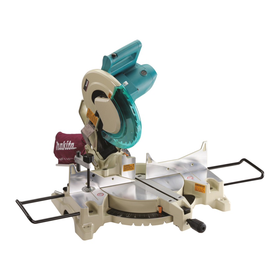
- Page 1 Slide Compound Saw 305 mm (12”) MODEL L S l 2 1 l Equipped with Electric Brake INSTRUCTION MANUAL DOUBLE INSULATION...
- Page 2 SPECIFICATIONS ......................Blade diameter 2") ......................25.4 mm 11") Arbor diameter Max cutting capacities 1 H x W ) Bevel angle Left 45" Right 45" Miter angle x 230 .120 230 mm mm x mm x 12-9/16" 9-1/16',) *11-15/16" 9-1/16',) 14-3/4"...
- Page 3 For Your Own Safety Read Instruction Manual Before Operating Slide Compound Saw Save it for future reference GENERAL SAFETY PRECAUTIONS (For All Tools) KNOW YOUR POWER TOOL. Read the owner’s manual carefully. Learn the tools applications and limitations, as well as the specific potential hazards peculiar t o KEEP GUARDS I N PLACE and in working order.
- Page 4 CORDS. EXTENSION Make sure your extension cord is i n good condition. When using an extension cord, be sure to use one heavy enough to carry will the current your product w i l l draw. An undersized cord cause a drop loss of in line voltage resulting in power and overheating.
- Page 5 ADDITIONAL SAFETY RULES 1. Wear eye protection. 2. Do n o t operate saw without guards place. Don't use the t o o l i n the presence of flammable liquids or gases. 4. Check the blade carefully for cracks or damage before operation. Replace cracked or damaged blade immediately.
- Page 6 Socket wrench Store the socket wrench in the wrench holder the rear of the tool after using it. Wrench holder Bench mounting saw When the tool is shipped, the handle locked in the lowered position. Release the handle from the lowered position by lower- ing it slightly and removing the chain from the screw on the motor housing.
- Page 7 Installing or removing saw blade CAUTION : Always be sure that the tool is switched off and unplugged before installing or removing the blade. Use the socket wrench to loosen the hex bolt which secures the center cover turning counterclockwise. Raise the safety cover and the center cover.
- Page 8 -Socket CAUTION: Use only the Makita socket wrench provided to install or remove the blade. Failure to do may result in overtightening or insufficient tightening of the hex bolt. This could cause serious injury to operator or others in the general vicinity of the tool.
- Page 9 Positioning kerf boards This tool is provided with kerf boards in the turn base. The kerf boards are factory-adjusted so that the saw blade does not contact the kerf boards. Before use, adjust the kerf boards as follows: First unplug the tool. Loosen the a l l screws (2 each on left and right) which secure the kerf boards.
- Page 10 Maintaining maximum cutting capacity This tool factory adjusted to provided the max. cutting capacity for 305 mm (12”) saw blade. When using a saw blade other than the 305 mm (12”) saw blade, adjust the lower limit position of the blade follows: First unplug the tool.
- Page 11 Positioning for adjusting the bevel angle t i l t s 45" The saw blade up t o t o the left and right. To adjust the bevel angle, loosen the lever a t the rear of the tool. For left bevel cutting, tilt the saw blade t o the left until the pointer points t o the de- sired angle.
- Page 12 Securing workpiece WARNING: extremely important to always secure the workpiece properly and tightely with the It i s vise. Failure to do so can cause the tool to be damaged and/or the workpiece to be des- troyed. PERSONAL INJURY MAY ALSO RESULT. Also, after any cutting operation, DO NOT raise the blade until the blade has come to a complete stop.
- Page 13 Holders and holder assembly (optional accessories) The holders and the holder assembly can be installed on either side as a convenient means of supporting workpieces horiziontally. Install them as shown in the figures. Then tighten the screws firmly to secure the holders and the holder assembly. CAUTION : Always support long workpieces level with the top surface of the turn base for accurate cuts and to prevent dangerous loss of control of the tuol.
- Page 14 Operation CAUTION .Make sure the blade is not contacting the workpiece, before the switch is turned on. etc. Do not apply excessive pressure on the handle when cutting. Too much force may result in overload of the motor and/or decreased cutting efficiency. *Gently press down the handle to perform the cut.
- Page 15 2. Slide (push) cutting (cutting wide workpieces) Workpieces up t o mm (3-1 1/16") high and 310 mm (12-3/16") wide or 107 (4-3/16") high and 290 mm (1 1-7/16") wide can be cut in the following way. Loosen the clamp screw on the arm so that the carriage can slide freely. Secure the workpiece with a vise.
- Page 16 CAUTION : During a bevel cut, it may create a condition whereby the piece cut will come to rest against the side of the blade. If the blade is raised while the blade is still rotating, this piece may be caught by the blade, causing fragments t o be dangerous.
- Page 17 6. Cutting crown and cove moldings .Crown and cove moldings can be cut on a compound miter saw with the moldings laid f l a t on the turn base. *There are two common types of crown moldings and one type cove molding: 52/38"...
- Page 18 When cutting crown and cove moldings, set the bevel angle and miter angle as indicated in the table ( A ) and position the moldings on the top surface of the saw base as indi- (B). cated in the table ( A I Table Bevel angle...
- Page 19 7. Cutting aluminum extrusion When securing aluminum extrusions, use spacer blocks or pieces of scrap as shown in the figure to prevent deformation of the aluminum. Use a cutting lubricant on the blade teeth when cutting the aluminum extrusion to prevent build-up of the aluminum mate- rial on the blade.
- Page 20 of wood Miter angle Thickness facing 0" Over mm ( 1 -3/16") Left and rioht 45" Over 21 (13/16") 60" Left and right Over 1 5 ( 9 / 1 6 " ) 9. Cutting repetitive lengths When cutting several pieces of stock to the same length, ranging from 305 mm (12") to 440 mm (17-5/16"), use of the plate (optional accessory) will facili-...
- Page 21 tool Carrying Make sure that the tool isunplugged. Secure the blade 0" bevel angle and the turn 60" base a t miter angle to the right. Secure the slide pole after pulling the carriage to- ward fully. Lower the handle fully and lock in the lowered position by hooking the chain to the screw on the motor hous,...
- Page 22 MAINTENANCE CAUTION : Always be sure that the tool is switched off and unplugged before attempting to perform inspection or maintenance. WARNING: Always be sure that the blade is sharp and clean for the best and safest performance. Adjusting the cutting angle This tool is carefully adjusted and aligned at the factory, but rough handling may have affected the alignment.
- Page 23 2) Bevel angle i) 0" bevel angle Push the carriage toward the guide fence and tighten the clamp screw on the arm. Loosen the lever a t the rear of the tool. Turn the hex bolt (A) on the turn base two or three revolutions counterclockwise to tilt the blade to the right.
- Page 24 i i ) 45" bevel angle Adjust the 45" bevle angle only after performing bevel angle adjustment. 0" To adjust left 45" bevel angle, loosen the lever and tilt the blade 45" t o the left. sure that the pointer on the Make arm points to 45"...
- Page 25 "Safety cover". Lubricate the sliding portions with machine oil to prevent rust. To maintain product SAFETY and RELIABILITY, repairs, any other maintenance or adjustment should be performed by Makita Authorized or Factory Service Centers, always using Makita replacement parts.
- Page 26 These accessories or attachments are recommended f o r use w i t h your Makita t o o l specified manual. The use of any other accessories o r attachments might present a risk o f injury t o persons. The accessories or attachments should be used o n l y in the proper and intended manner.
- Page 27 Oci - 2 5 - 305 m m (12") SLIDE COMPOUND SAW Model LS1211...
- Page 28 Note: The switch, noise suppressor and other part configurations may differ from country to country.
- Page 29 2 5 - MODEL LS1211 A& A: D 'i\M DESCRIPTION DESCRIPTION MACHINE H e r M a r 7 5 Bo11 center Plate c u m , Rubber Sleeve center Elbow Flal Head Screw rowon 0 Ring 42 spr<,,y 45...
- Page 30 Makita’s Factory or Authorized Service Centers. If inspection shows the trouble is caused by defective workmanship or material, Makita will repair (or a t our option. replace) without charge. This Warranty does not apply where:...