Advertisement
Quick Links
Items Supplied >
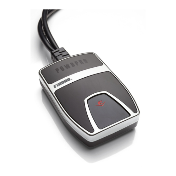
1 – Powrpro Black Fuel Injection Module
2 – Zip Ties 6"
1 – Zip Tie 8"
1 – Velcro Strip
Instruction Manual >
Read all instructions carefully and completely before installing your new POWRPRO module. It is
recommended that a qualified mechanic or technician install this product.
1. Flip up seat, to gain access to radiator reservoir area.
2. Remove Dzus fastener to remove simulated fuel tank cover, over airbox housing. Depending on
which model V-Rod is being worked on, the front shrouds covering the upper front frame section may
also need to be removed.
3. Place Fi2000 in under-seat area, run fuel injector connector harness up right side frame rail between
top right frame rail, and radiator overflow tank, see Figure 1. At the rear of the airbox, route the
harness below the airbox, and downward next to the inner radiator hose. Unplug both stock fuel
injector connectors, on the front and rear injectors between the engine cylinders, see Figure 2.
These are disconnected, by depressing the metal springs that are on the end of each female
connector. The stock female connectors are marked "F" and "R", noting which connector goes to the
front and rear injector, be sure to pay attention to this. Now connect the longer male Fi2000
connector to the front female H.D. connector. Plug shorter Fi2000 male connector into the stock rear
female H.D. connector. Then plug the longer female Fi2000 connector onto the front stock H.D.
injector. Plug the shorter Fi2000 female connector onto the rear injector. Each injector connector pair
should rest underneath each respective injector.
4.
Locate the rear oxygen sensor connector and follow the harness up to the under-seat area behind the
radiator overflow tank. Pull the stock connectors up from below the overflow tank and disconnect, see
Figure 1. The shorter Fi2000 Oxygen sensor harness with male and female connectors will plug into
each of these stock male and female connectors. Tuck the connectors back underneath the bracket
behind the radiator overflow tank.
5. Route the front oxygen sensor harness along the right upper frame rail as was previously done with
the fuel injector connector harness. Continue routing the harness forward along the frame rail past the
radiator overflow tank, and up past the airbox. Route the harness in front of the airbox, and over the
top of the airbox intake snorkel, behind the headstay. Remove the left front frame/tank cover to gain
access to the electrical connections above the front cylinderhead; removal of this cover may vary
depending on which model V-Rod is having the module installed on it. Route the front Fi2000 O
sensor harness from the headstay area, down towards, the left front frame rail, and continue routing
the harness along the inside of the frame rail towards the radiator and left footpeg mounting boss.
Now locate the front oxygen sensor on the front headpipe, and trace the oxygen sensor harness back
to the connectors tucked between the left front frame rail and plastic radiator shroud, see Figure 3.
Continued to next page!
DISCLAIMER: NOT LEGAL FOR SALE OR USE IN CALIFORNIA ON ANY POLLUTION CONTROLLED
.
MOTOR VEHICLES
DOCUMENT NO. 0017
04/16
23801 E. La Palma Ave., Yorba Linda, Ca 92887 Ph. 714.692.8180, Fax. 714.692.5016
®
REV. A
Application(s) >
HARLEY V-ROD
692-1613B
1
www.cobrausa.com
2008 - 2010
Page 1 of 3
2
Advertisement

Summary of Contents for Cobra Fi2000 PowrPro Black
- Page 1 23801 E. La Palma Ave., Yorba Linda, Ca 92887 Ph. 714.692.8180, Fax. 714.692.5016 ® www.cobrausa.com Items Supplied > Application(s) > 1 – Powrpro Black Fuel Injection Module HARLEY V-ROD 2008 - 2010 2 – Zip Ties 6” 1 – Zip Tie 8” 1 –...
- Page 2 23801 E. La Palma Ave., Yorba Linda, Ca 92887 Ph. 714.692.8180, Fax. 714.692.5016 ® www.cobrausa.com Instruction Manual > Page 2 of 3 692-1613B 5. Continued: Pull these connectors out, and disconnect them. Plug the corresponding Fi2000 connectors into each of the stock male and female connectors, and tuck the connectors back in between the frame rail and plastic shroud.
- Page 3 23801 E. La Palma Ave., Yorba Linda, Ca 92887 Ph. 714.692.8180, Fax. 714.692.5016 ® www.cobrausa.com Instruction Manual > Page 3 of 3 692-1613B FRONT FEMALE INJECTOR LONGER Fi2000 CONNECTOR WITH FEMALE CONNECTOR LONGER MALE Fi2000 ON FRONT CYLINDER CONNECTOR INJECTOR NOTE: REAR INJECTOR AND Fi2000 CONNECTION NOT VISIBLE...


