Advertisement
Quick Links
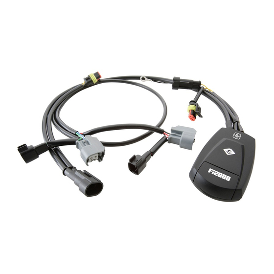
Items Supplied >
1 – Fi2000R Fuel Injection Module
5 – Zip Ties 6"
1 – Velcro Stripe
Instruction Manual >
ATTENTION: All 2007 Harley SOFTAIL models manufactured before NOVEMBER 1, 2006 require
an ENGINE CONTROL MODULE CALIBRATION update from a Harley Davidson Dealer; please
reference Harley Davidson SERVICE BULLETIN M-1186. This Fi2000 is meant to function on all
2007 SOFTAIL models with this update and all 2007 SOFTAIL models manufactured after this date
which should already have this update installed, check with your local dealer for verification.
Read all instructions carefully and completely before installing your new Fi2000 module. It is
recommended that a qualified mechanic or technician install this product.
1. Remove the seat and air cleaner assembly, remove both front and rear gas tank mounting bolts. Prop the rear
of the gas tank up approximately 2".
2. Locate the factory connector on each fuel injector. Depress the clip on the connector and pull the connector
free and move it out of the way. Note: A pair of needle nose pliers and a long flat blade screwdriver helps w ith
this job. If you need additional access to the fuel injector connectors, you can remove the Idle Air solenoid by
removing the two 5/16'' bolts holding it on and loosening the Torx #20 screw on throttle cable bracket. Make
sure to use thread-locking compound when refitting the two 5/16" bolts and correctly position the o-ring when
reattaching.
3. Lay the Fi2000 module in the area underneath the seat, do not attach it to the motorcycle, route the injector wire
harness forward up the right side of the frame backbone, see Figure 1. Route the forward set of connectors
under the upper motor mount.
4. Attach the Fi2000 module's forward injector plug, to the front injector. Take the original female H.D. connector
and insert the corresponding Fi2000 male connector into it, refer to Figure 2.
5. Attach the Fi2000 module's rear female injector plug, onto the rear injector. Then take the original female H.D.
connector and insert the corresponding male Fi2000 connector, into it. (See Figure 2)
6. It is now time to install the oxygen sensor harnesses. Remove the battery for access to the area underneath it
and to aid in harness installation. To help installation, disconnect square connector at right rear corner of battery
to help installation of O
main harnesses going to the fuse box and the right rear corner of the frame in the battery area. The longer
harness continues down past the rear of the transmission and the shorter harness comes forward under the
bottom of the oil tank until it is visible in the cut out area where the battery sits. Unplug the factory O
connection and plug in the corresponding male and female connectors.
7. Now route the longer harness up the right side of the frame rail. Following the factory harness and zip tie it to the
harness in 3 locations.
8. Remove the 2 Allen bolts that secure the voltage regulator bracket to the block, and remove the rectangular
cover over the top of this bracket. Ease the voltage regulator forward just enough to access the front O
connector. Unplug the connector and then plug the Fi2000 female connector into the original HD male
connector. Replace this connection into the voltage regulator bracket and re-assemble onto the bike, making
sure the Fi2000 wire exits the top of the cover just like the original wire went in.
* Cobra recommends you always wear a helmet while riding. Please never operate your motorcycle while under
the influence of alcohol and/or drugs. Enjoy the new look of your motorcycle and please ride safely.
DOCUMENT NO. 0017
REV. A
09/07
23801 E. La Palma Ave., Yorba Linda, Ca 92887 Ph. 714.692.8180, Fax. 714.692.5016
sensor harnesses, see Figure 3. Route the two O
2
Application(s) >
HARLEY SOFTAIL
692-1607CL
sensor harnesses down between the
2
1
www.fi2000r.com
07-08
Page 1 of 4
sensor
2
2
Advertisement

Related Manuals for Cobra Fi2000


Summary of Contents for Cobra Fi2000
- Page 1 3. Lay the Fi2000 module in the area underneath the seat, do not attach it to the motorcycle, route the injector wire harness forward up the right side of the frame backbone, see Figure 1. Route the forward set of connectors under the upper motor mount.
- Page 2 Page 2 of 4 692-1607CL 9. Now plug the other Fi2000 connector into the oxygen sensor wire and zip tie this connection to the left frame tube in a location that will not allow the wires to touch the exhaust pipe, Figure 4 10.
- Page 3 BETWEEN FRAME BATTERY RAIL AND STOCK FIGURE 1 HARNESS ORIGINAL REAR H.D. ORIGINAL FRONT FEMALE INJECTOR CONNECTOR H.D. INJECTOR WITH MALE Fi2000 CONNECTOR WITH MALE CONNECTOR Fi2000 INJECTOR CONNECTOR REAR FEMALE Fi2000 INJECTOR CONNECTOR FRONT FEMALE Fi2000 ON REAR INJECTOR...
- Page 4 23801 E. La Palma Ave., Yorba Linda, Ca 92887 Ph. 714.692.8180, Fax. 714.692.5016 www.fi2000r.com Instruction Manual > Page 4 of 4 692-1607CL FIGURE 3 Fi2000 Default pot setting Aftermarket Air Cleaner, Exhaust Download: From Bulletin: M-1186 Default Pot Settings: Green Yellow...