Advertisement
Quick Links
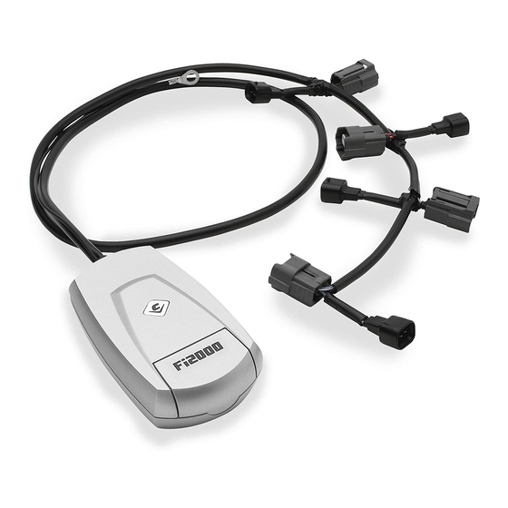
Items Supplied >
1 – Powrpro Black Fuel Injection Module
6 – Zip Ties 4"
1 – Velcro Stripe
Instruction Manual >
Read all instructions carefully and completely before installing your new POWRPRO module. It is
recommended that a qualified mechanic or technician install this product.
1. Remove left and right side cover on motorcycle below seat. Be careful not to scratch paint on lower section of
panel on both sides.
2. Underneath edge of seat, remove bolts retaining it on left and right sides. With both side bolts removed, lift front
portion of seat, if equipped with a seat heater, disconnect electrical connector at rear of seat and fully remove
seat.
3. Remove M8 bolts securing rear of fuel tank on each side, rotate tank up at front slightly and remove rubber
grommets between tank mount and frame. This will prevent grommets from falling down inside of frame.
Remove M6 bolt at rear of fuel tank and remove ground wire.
4. Prop rear of fuel tank up and disconnect quick release fuel coupling on bottom of tank, by pressing in green tabs
on each side of coupler and pulling fuel coupling downward from tank, Figure 1. Be sure to place a shop rag
under fuel line and perform installation in a well ventilated area. Disconnect the fuel tank electrical connector
along bottom of fuel tank also, see Figure 1. Be sure to disconnect two vacuum lines from rear lower left corner
of fuel tank, for tank removal, see Figure 2.
5. Assistance is recommend to carefully pull fuel tank slightly rearwards to disengage from front rubber mounting
lugs. Pull tank approximately 6 to 8 inches rearward and lift front and rear of tank upward and off at same time.
Fully remove tank and set in secure ventilated area.
6. Place the Powrpro Tuner
area covered by the left side panel, see Figure 3.
7. Route all three PPT wire harnesses towards the front of the motorcycle, the shortest harness with long male and
female connectors will go down towards the rear cylinder O
alongside the left upper side of the cast frame and can be attached to other harness retaining clips. Run the
injector harness to the area between the engine cylinders and the longest with another set long connectors down
the left front cast frame member to the front cylinder O
8. From left side of motorcycle, locate the rear fuel injector connector between cylinder heads, see Figure 5. Pull the
"RED" pull tab up towards the top portion of the connector, assistance will be needed to prevent the injector from
rotating during this procedure, see Figure 6. Once the Red tab is pulled upward, push in on the black tab below it,
see Figure 6 & 7. While pushing in on black tab, pull entire connector upward and remove from injector. Right
angled long nose pliers and assistance with a flat blade screwdriver from left side of engine will help with this. It
may be necessary to snip the zip tie from the injector wires to the fuel rail, to allow adequate wire length to free
connector from injector. Pull injector connector outward towards left side of motorcycle. Install the shorter (closer
to PPT module), female connector onto rear injector. Mate stock female connecter with male PPT connector. Be
sure all connectors seat firmly and Red lock tab on stock female connector is locked, see Figure 8.
DISCLAIMER: NOT LEGAL FOR SALE OR USE IN CALIFORNIA ON ANY POLLUTION CONTROLLED
.
MOTOR VEHICLES
DOCUMENT NO. 0017
REV. A
08/16
23801 E. La Palma Ave., Yorba Linda, Ca 92887 Ph. 714.692.8180, Fax. 714.692.5016
®
™
(PPT) in the area in front of the ECU on the left side of the motorcycle under the
Application(s) >
CROSS COUNTRY TOUR
CROSS COUNTRY 8 BALL
CROSS COUNTRY MAGNUM
MAGNUM X-1
92-1055B
sensor connectors. The other two harnesses route
2
sensor connectors, see Figure 4.
2
1
www.fi2000r.com
2016
2016
2016
2016
Page 1 of 5
Advertisement

Related Manuals for Cobra Fi2000 PowrPro


Summary of Contents for Cobra Fi2000 PowrPro
- Page 1 23801 E. La Palma Ave., Yorba Linda, Ca 92887 Ph. 714.692.8180, Fax. 714.692.5016 ® www.fi2000r.com Items Supplied > Application(s) > 1 – Powrpro Black Fuel Injection Module CROSS COUNTRY TOUR 2016 CROSS COUNTRY 8 BALL 2016 6 – Zip Ties 4” CROSS COUNTRY MAGNUM 2016 1 –...
- Page 2 23801 E. La Palma Ave., Yorba Linda, Ca 92887 Ph. 714.692.8180, Fax. 714.692.5016 ® www.fi2000r.com Instruction Manual > Page 2 of 5 92-1055B 9. Locate front cylinder injector connector from left side of motorcycle, Figure 5. Pull Red lock tab upward, see Figures 6 and 7, depress black tab under it and pull connector straight up and free from injector.
- Page 3 23801 E. La Palma Ave., Yorba Linda, Ca 92887 Ph. 714.692.8180, Fax. 714.692.5016 ® www.fi2000r.com Instruction Manual > Page 3 of 5 92-1055B FUEL TANK ELECTRICAL CONNECTOR FUEL LINE QUICK DISCONNECT FUEL TANK FITTING VACUUM LINES FIGURE 1 FIGURE 2 HARNESSES TO REAR OXYGEN...
- Page 4 23801 E. La Palma Ave., Yorba Linda, Ca 92887 Ph. 714.692.8180, Fax. 714.692.5016 ® www.fi2000r.com Instruction Manual > Page 4 of 5 92-1055B PULL RED LOCK REAR CYLINDER FRONT CYLINDER PRESS BLACK TAB UP FUEL INJECTOR / FUEL INJECTOR / TAB IN TO REMOVE CONNECTOR...
- Page 5 23801 E. La Palma Ave., Yorba Linda, Ca 92887 Ph. 714.692.8180, Fax. 714.692.5016 ® www.fi2000r.com Instruction Manual > Page 5 of 5 92-1055B LEFT FRONT FRAME RAIL STOCK FRONT MALE O STOCK FRONT FEMALE CONNECTOR CONNECTOR PPT FEMALE FRONT PPT MALE O FRONT O CONNECTOR CONNECTOR...