Advertisement
Quick Links
-
Items Supplied >
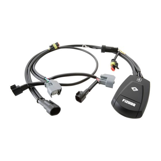
1 – Fi2000AT Fuel Injection Module
1 – Zip Tie, 3/16" x 8"
1 – Velcro Strip
Instruction Manual >
Read all instructions carefully and completely before installing your new Fi2000AT module.
It is recommended that a qualified mechanic or technician install this product.
Before installing it is recommended that the fuel tank be low on fuel.
1. Remove the seat, and the chrome right hand cover from the engine. Remove the two dome head nuts holding the
rear of the fuel tank on.
2. Position the Fi2000 on top of the ECU (under the seat) and feed the wire harness under the front seat bracket,
then feed the harness forward underneath the rear fuel tank mounting bracket. Lift up the fuel tank just enough to
slip the wire harness under the rear of the fuel tank, make sure the harness does not get pinched between the fuel
tank and the frame as the tank is lowered down, see Figure 1. Zip-tie the harness to the other harnesses under
the tank.
3. Feed the remaining portion of the wire harness forward and down through the coil bracket opening, see Figure 2.
Locate the white Raider 6-pin connector behind the coil-mounting bracket; disconnect this connector.
4. Plug the Fi2000 connectors into the corresponding 6 pin connectors that were previously unplugged in Step 3.
Reinstall the chrome right side cover.
5. Locate the oxygen sensor on the muffler body near the power valve and trace the wire on it back up to under the
seat, where it's male and female connectors are located. Move the fuse block out of the way, by depressing the
plastic tab between the housing and the steel-mounting tab, and pull it upward out of the way to gain access to the
oxygen sensor connectors mounted on the plastic tab. Disconnect the oxygen sensor by pulling the tab on the
female connector outward and pulling the male connector towards the front of the bike, see Figure 3.
6. Feed the female oxygen sensor connector and harness from the Fi2000 down to the stock male oxygen sensor
connector, and connect the two. Now connect the male Fi2000 oxygen sensor connector to the stock female
oxygen sensor connector, see Figure 4, once this has been done reinstall the fuse block onto its mounting tab.
7. Using the supplied Velcro pads, place the module in the position shown, in Figure 5. Attach the black ground wire
from the Fi2000 to the 5 mm socket head bolt securing the battery ground wire, see Figure 5. Before reinstalling
the seat, verify connections.
8. Verify the wire connections; turn on the ignition and watch the Fi2000 LED logo, confirm that the LED blinks
several times then turns off. If you do not see any blinking, it may be necessary to wait for the alarm to reset (if
applicable) and try again. Also confirm the side stand is up, bike is in neutral, clutch is in and handle bar engine
switch is set to run (where applicable). Start the bike and the Fi2000 logo should remain solid red, which confirm
the unit is fully functioning. If it flashes while the bike is running, turn off the bike and recheck that all harness
connections (injectors, ground wire, and O2 sensors when applicable) have been properly made. Re-verify by
turning ignition on while watching for flashing LED, prior to starting. Start and confirm LED remains ON solid red.
NOTE: Make sure ignition is turned off before attempting to change any Fi2000 harness connections.
* It is recommended that you always wear a h elmet while riding. Please never operate your motorcycle while
under the influence of alcohol and/or drugs. Enjoy the new power of your motorcycle and please ride safely.
DOCUMENT NO. 0017
REV. A
05/11
23801 E. La Palma Ave., Yorba Linda, Ca 92887 Ph. 714.692.8180, Fax. 714.692.5016
®
Application(s) >
YAMAHA RAIDER
92-1777AT
1
www.fi2000r.com
2008-2010
Page 1 of 3
Advertisement

Related Manuals for Cobra Fi2000


Summary of Contents for Cobra Fi2000
- Page 1 2. Position the Fi2000 on top of the ECU (under the seat) and feed the wire harness under the front seat bracket, then feed the harness forward underneath the rear fuel tank mounting bracket. Lift up the fuel tank just enough to slip the wire harness under the rear of the fuel tank, make sure the harness does not get pinched between the fuel tank and the frame as the tank is lowered down, see Figure 1.
- Page 2 RAIDER COIL AND WIRE HARNESS BRACKET SECURED WITH EXISTING METAL PRONG RAIDER MALE RAIDER FEMALE CONNECTOR CONNECTOR FEMALE MALE Fi2000 FI2000 CONNECTOR CONNECTOR FIGURE 2 DEPRESS TAB STOCK FEMALE DISCONNECT MALE ON FUSE BOX CONNECTOR WITH O2 SENSOR HERE TO...
- Page 3 Fi2000 INSTALLATION LOCATION FIGURE 5 NOTE: For California riders we offer Air Resources Board approved Fi2000R ARB units. (ARB E.O. No. D-633-1). All other Fi2000 models are not legal for street use in California. DOCUMENT NO. 0018 REV. A 05/11...