
Related Manuals for Honeywell Z4 G4


Summary of Contents for Honeywell Z4 G4
- Page 1 Z4 G4 Honeywell Planning, Installation and Service Guide HWDOC-XX585-en-B August 2020...
- Page 2 Honeywell International Sàrl. While this information is presented in good faith and believed to be accurate, Honeywell disclaims the implied warranties of merchantability and fitness for a purpose and makes no express warranties except as may be stated in its written agreement with and for its customer.
-
Page 3: Table Of Contents
Contents Chapter 1 - About this guide 1.1 Revision history Chapter 2 - Planning 2.1 Introduction 2.1.1 Furniture options 2.1.2 Software requirements 2.2 Workstation overview 2.2.1 Front view 2.2.2 Rear view 2.2.3 Internal view 2.2.4 System board 2.3 Specifications 2.3.1 System specifications 2.3.2 Operating power requirements 2.3.3 Regulatory and safety compliance 2.4 Specific slot configuration... - Page 4 3.10.2 Matrox Extio2 Remote Peripheral Solution (RPS) Chapter 4 - Operation 4.1 Starting up your workstation 4.1.1 Turn on power and check status 4.1.2 Configuring RAID in HP Z4 G4 workstation 4.1.3 Check LCNP status 4.2 Network connections 4.2.1 Ethernet network 4.2.2 Local Control Network...
- Page 5 4.3.1 To download drivers from HoneywellProcess.com 4.3.2 Installing Windows operating system 4.3.3 Installing driver 4.3.4 To run the BIOS automation script on HP Z4 G4 workstation Chapter 5 - Servicing 5.1 Accessing the enclosure of the workstation 5.1.1 Shutdown workstation 5.1.2 Remove the workstation from an Icon Series console...
-
Page 6: Chapter 1 - About This Guide
Honeywell factory or has manuals dedicated to its installation and service. This workstation is not a standard Hewlett Packard model and you cannot order it independently from Hewlett Packard. - Page 7 Chapter 1 - About this guide Publication Content Type Implementation Guide operation, servicing/troubleshooting (EPDOC-X478-en-511A) Experion LCN Planning, ELCN system planning, hardware/software Installation, and Service Guide installation, servicing/troubleshooting (HWDOC-X479-en-E) Experion LCN Specification General ELCN technical specifications (ELCN03) Fault Tolerant Ethernet FTE system installation, servicing/troubleshooting Installation and Service Guide (EPDOC-XX36-en511A) Universal Embedded...
-
Page 8: Revision History
Chapter 1 - About this guide Publication Content Type Experion R511 Software Describes Experion R511 features/enhancements, Change Notice (EPDOC- overall product, release interoperabilities, system X166-en-511A) dependencies, problem resolutions, known issues, special considerations Customer Release Guide TPN/TPS Migration information (ELCN migration R687 (CRG-687) Information included) TPN R687 Software Change... -
Page 9: Chapter 2 - Planning
Workstation configuration Introduction Platforms sold by Honeywell are engineered for the process control mission of Experion systems to provide consistent, robust performance. Through an extensive qualification process, Honeywell defines specific peripheral devices, slot locations, and BIOS settings for best performance and reliability, sometimes even adding cooling fans for longer service. -
Page 10: Furniture Options
Classic Console Mounting Fixed Rails (4U with PC) TP-PCMCS1 Classic Console Mounting Slide Tray (5U with PC) The initial release of HP Z4 G4 workstation is not supported in Honeywell Z / EZ and Cabinet mounting and support for these furniture will be provided later. 2.1.2 Software requirements The following are the Experion platform and software models. -
Page 11: Rear View
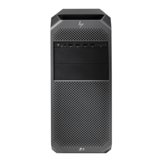
2. Audio-out (headphone)/Audio-in (microphone) combo jack 3. USB 3.0 charging port 4. USB 3.0 ports (3) 5. SD Card reader 6. External drive bays 2.2.2 Rear view The following image illustrates the rear view of the HP Z4 G4 workstation. - 11 -... -
Page 12: Internal View
5. Rear I/O (top to bottom): audio in/out, Keyboard/Mouse PS/2 6 USB 3.1 G1 Type-A 2 x 1GbE ports 6. Side panel barrel keylock (optional) 2.2.3 Internal view The following image illustrates the internal view of HP Z4 G4 workstation. - 12 -... -
Page 13: System Board
12. 3.5-inch hard drive 13. Drive cage 14. Front IO/User Interface (FIOUI) module 15. 2.5-inch solid-state drive 16. M.2 solid-state drive 17. Front bezel 2.2.4 System board The following image illustrates a system board of HP Z4 G4 workstation. - 13 -... - Page 14 Chapter 2 - Planning Number Description Front audio Front USB 3.0 Internal USB 2.0 Internal USB 3.0 Keyboard/mouse Network Rear audio Rear USB 2.0 Rear USB 3.0 Serial (optional) Speaker ThunderboltTM GPIO PCIe2 x1 PCIe3 x16 PCIe2 x4 PCIe3 x8 - 14 -...
- Page 15 Chassis solenoid lock Boot Block Recovery (BBR) jumper Clear CMOS button ME/AMT flash override Password jumper Optional supported components The following can be mounted in the Z4 G4. Model number Description TP-RPWR01 BREAKER/CONNECTOR BRACKET ASSM TP-RPSF02 REMOTE PERIPHERALS SOLUTIONS (EXTIO2)
-
Page 16: Specifications
Chapter 2 - Planning Specifications System specifications Regulatory and safety compliance Features 2.3.1 System specifications Microprocessor Microprocessor Specification Tab -100 Single Intel Xeon Processor W-2123 3.60GHz (or faster) Level Cache 8.5MB cache (or better) Chipset Intel® C422 Chipset Expansion slots Expansion slots Specification Bus type... - Page 17 Chapter 2 - Planning Video Video Specifications Video type NVIDIA Quadro P620 Video memory 2GB minimum Maximum DP 1.4 Resolution HDR 5120 x 2880 at 60Hz (30-bit color) 5K Display Support HDR 5120 x 2880 at 60Hz (30-bit color) 4K Display Support HDR 4096 x 2160 at 60Hz or 3840 x 2160 at 60Hz Maximum DVI-D DL Resolution 2560 x 1600 at 60Hz via 3rd party adapter...
- Page 18 Chapter 2 - Planning Environmental Specifications wet bulb Non-operating: 10% to 90% RH, non-condensing, 35° C maximum wet bulb Maximum altitude Operating (with Rotational Hard drives): 3,048 m (10,000 feet) Non-operating: 12,192 m (40,000 feet) Maximum operating temperature is reduced as altitude increases.
- Page 19 Chapter 2 - Planning Form factor Form factor Specifications Form Factor/Configuration Mini-Tower Height 15.2" (386mm) Width 6.65" (169mm) Depth 17.5" (445mm) Weight Maximum: 17.3 kg (38.2 lbs.) Drive bays Drive bays Specifications Internal Two 2.5”/3.5” External Two 5.25”, One slim ODD External peripherals External peripherals Specifications...
-
Page 20: Operating Power Requirements
A Local Control Network Processor (LCNP) board and LCN Media Access Unit (MAU) are no longer used if the Workstation has been upgraded to be an ELCN node. Quad Video Graphics is the default option offered with the Honeywell Configured HP Z4 G4 workstation. The following board configuration layouts specifies available system configurations. -
Page 21: Basic Board Configuration (Standard)
Chapter 2 - Planning Basic board configuration (Standard) Basic Board Configuration for Quad Screen EPKS (T-node) Systems Basic Board Configuration for Quad Screen EPKS (ES-C / ES-F node) FTE Systems Basic Board Configuration for Quad Screen PCUS (Dual LCN) systems Basic Board Configuration for Quad Screen PCUS (Single LCN) systems Basic board configuration for Matrox Extio2 (TP-RPSF02) 2.4.1... -
Page 22: Basic Board Configuration For Quad Screen Pcus (Dual Lcn) Systems
Chapter 2 - Planning Slot no Slot type Description PCIe Gen3 x4PCH PCIe Gen3x16 PCIe Gen3 x4 PCH PCIe Gen3 x16 nVidia Quadro P620 Mechanical Only Power Adapter Harness 2.4.4 Basic Board Configuration for Quad Screen PCUS (Dual LCN) systems Slot no Slot type Description... -
Page 23: Basic Board Configuration For Matrox Extio2 (Tp-Rpsf02)
Chapter 2 - Planning 2.4.6 Basic board configuration for Matrox Extio2 (TP-RPSF02) Slot no Slot type Description PCIe Gen3 x8 COM PORT PCIe Gen3 x4PCH PCIe Gen3x16 PCIe Gen3 x4 PCH PCIe Gen3 x16 Extio2 Mechanical Only Power Adapter Harness Memory configurations 16GB (2x8GB) RDIMM ECC is the standard installed memory for systems. -
Page 24: Workstation Information
Classic Console Mounting Fixed Rails (4U with PC) TP-PCMCS1 Classic Console Mounting Slide Tray (5U with PC) The initial release of HP Z4 G4 workstation is not supported in Honeywell Z / EZ and Cabinet mounting and support for these furniture will be provided later. 2.7.2... -
Page 25: Environmental Specifications For Cabinets And Consoles
Chapter 2 - Planning 2.7.3 Environmental specifications for cabinets and consoles The following table lists the allowable operating environmental limitations for cabinets and consoles. Environmental Specifications Operating 5°C to 35 °C (40 °F to 95 °F) temperature Storage -40 °C to 60 °C (-40 °F to 140 °F) temperature Humidity Operating: 10% to 85% RH, non-condensing, 35°... - Page 26 Chapter 2 - Planning **ANSI/ISA-S71.04-1985 Environmental Conditions for Process Measurement and Control Systems: Airborne Contaminants. - 26 -...
-
Page 27: Chapter 3 - Installing
CHAPTER NSTALLING Installation tasks Power and grounding requirements Installing workstation in Icon Series console Installing workstation in the Experion Orion Console Installing workstation in Classic console Connecting cables Connecting to the Experion Orion console monitor Connecting adapters Connecting touchscreen adapter cable Remote Peripheral Solution Installation tasks The specific tasks you need to perform vary depending upon the type of furniture in which you are... -
Page 28: Ac Power Warning
Chapter 3 - Installing cord. AC Power warning Selecting the correct power setting 3.2.1 AC Power warning ATTENTION The power supply circuit is connected to AC power when the power cable is connected. The power control switch on the front panel only enables the power supply circuit outputs. It is strongly recommended that the power cord be connected to a clean power source with backup such as an Uninterruptible Power Source (UPS). -
Page 29: Connect System Cables
Chapter 3 - Installing 3. Remove the adhesive from the air gasket (“L” shaped foam) and place it on top of the workstation as shown in the following “Air flow and air dam arrangement” figure. The adhesive keeps the gasket in place. The gasket stops the exhaust air from re-circulating around the workstation. 4. - Page 30 Chapter 3 - Installing To connect system cables 1. Connect the USB mouse and USB keyboard extension cables to the USB connectors. 2. Connect the audio cable from the amplifier to the audio (green) port 3. If you are not using Fault Tolerant Ethernet (FTE), connect the Ethernet cable to the RJ-45 connector on the onboard Network Interface port.
-
Page 31: Installing Workstation In The Experion Orion Console
This section provides instructions for installing a newly purchased Honeywell workstation in a newly purchased Honeywell Classic console. The workstation is packaged in the manufacturer’s OEM shipping carton and then shipped from the Honeywell factory. This procedure assumes that a new Classic console is shipped from the Honeywell factory with workstation hardware pre-installed. - Page 32 (when viewed facing the workstation front bezel) with the workstation approximately 7,6 cm [3 inches] forward from its fully install position. ATTENTION In the following three photos, a different workstation is shown. The HP Z4 G4-based workstation is mounted using the same procedure. - 32 -...
- Page 33 The second wedge handle assembly included with this kit is not used in the installation of the HP Z4 G4 workstation. 8. Push the side spacers in until the handle is flush with the front flange of the side mounting brackets.
-
Page 34: Install Workstation In Classic Console Using Slide Tray Mount Option
The following image illustrates a slide tray mounting kit TP-PCMCS1-100 installed in a Classic console, as would be the case when a new Classic console and slide tray mounting kit is received from a Honeywell factory. To install the workstation in classic console furniture using the slide tray mount option 1. - Page 35 ATTENTION In the following five (5) photos, a different workstation is shown. The HP Z4 G4-based workstation is mounted using the same procedure. 5. Place one (1) foam wedge handle assembly between the left side mounting bracket and the left side of the workstation (when viewed facing the workstation front bezel) with the workstation approximately 7,6 cm [3 inches] forward from its fully install position.
- Page 36 Using a ¼” open end wrench or small crescent wrench tighten the hex threaded standoff to lock each stop peg in place. The following image illustrates the HP Z4 G4 workstation installed in Classic console with the console door opened.
-
Page 37: Connecting Cables
Chapter 3 - Installing 8. Refer to section Connecting cables. Connecting cables This section contains instructions for connecting the power cord and cables to the workstation platform. Your configuration may not have all the card connections. Connect cables to the workstation Connect remaining cables and power 3.6.1 Connect cables to the workstation... - Page 38 Category 3 wiring, force the network speed to 10 Mbps to ensure reliable operation. 9. Connect the AC power cord. The following image illustrates the rear view of HP Z4 G4 workstation. The following table lists the slot numbers for the making the cable connections.
-
Page 39: Connect Remaining Cables And Power
Chapter 3 - Installing Serial Slot Card Connection from Connection to LCNP4e2 Serial port from LCNP4e2 Serial port D-type male 9 pin female connector of interface connector (serial cable to IKB/OEP keyboard port) adaptor 3.6.2 Connect remaining cables and power NOTE A Local Control Network Processor (LCNP) board and LCN Media Access Unit (MAU) are no longer used if the Workstation has been upgraded to be an ELCN node. -
Page 40: Connecting Adapters
Chapter 3 - Installing Connecting adapters The workstation has standard 9-pin serial port COM 1, which can be used only for IKB or OEP serial keyboard connection. For serial touch screen connection, use USB to serial converter. OEP/IKB adapter configurations Install OEP/IKB adapter 3.8.1 OEP/IKB adapter configurations... -
Page 41: Install Oep/Ikb Adapter
Chapter 3 - Installing Figure 3.4 OEP/IKB adapter connections for IKB with Annunciator relay 3.8.2 Install OEP/IKB adapter To install OEP/IKB adapter 1. Locate a safe location for the OEP/IKB adapter box and secure it using the supplied Velcro. 2. Locate a safe location to place the OEP/IKB power adapter box and secure it using the supplied Velcro. - Page 42 Chapter 3 - Installing 7. Insert the round DIN plug of the supplied IKB PS/2 cable (51305381-500) into the PS/2 connector on the OEP/IKB module assembly (51305776-100). 8. Connect the free end of the IKB PS/2 cable (51305381-500) to the keyboard PS/2 port on the workstation.
-
Page 43: Connecting Touchscreen Adapter Cable
Chapter 3 - Installing 11. Perform the following to connect the IEC power cord (51305830-100): a. Connect one female end to the OEP/IKB power adapter (51197184-100). b. Connect the other female end to the power entry. c. Connect the male end to the original workstation power cord. Connecting touchscreen adapter cable 3.9.1 To connect the supplied touchscreen adapter cable to... -
Page 44: Connect Touchscreen And Oep Adapter Cables
This connection is for an Icon Series console. Connect the mixed USB and serial port solutions as illustrated in the following image. 3.10 Remote Peripheral Solution The Honeywell configured HP Z4 G4 workstation can be remotely accessible through Dell/Wyse Thin client RPS or Matrox Extio2 RPS. - 44 -... -
Page 45: Dell/Wyse Thin Client Rps
3.10.1 Dell/Wyse Thin Client RPS The Honeywell configured HP Z4 G4 Workstation can be remotely accessible through Dell/Wyse Thin Client Remote Peripheral Solution that can support CAT5 standard length. The Dell/Wyse thin client extends the audio, video, and USB signals through a network cable connection to the CPU of a remote computer. -
Page 46: Chapter 4 - Operation
While performing the following steps, you cannot access the information present in the hard drives. To configure RAID 1 in HP Z4 G4 workstation 1. Turn on the workstation. 2. Press F10 on the keyboard to enter the system BIOS. -
Page 47: Check Lcnp Status
Chapter 4 - Operation 6. Restart the workstation and press <Clt><I> when prompted. The Intel(R) Matrix Storage Manager screen appears. 7. Use the UP/DOWN arrow keys to highlight the options. 8. Select the option Create RAID Volume and press Enter. 9. -
Page 48: Ethernet Network
Processor card model no. TP-LCNP05. This card provides the communication path for the Honeywell Configured HP Z4 G4 to other LCN modules. The LCNP4E2 consists of a PCI Express 3.3 Volt LCNP4E2 full height and half-length Size card, a MAU cable and the LCN MAU (Media Access Unit).. -
Page 49: Installing Experion On Hp Z4 G4 Workstation
Chapter 4 - Operation Installing Experion on HP Z4 G4 workstation 4.3.1 To download drivers from HoneywellProcess.com 1. Download the drivers from following links: For EPKS R5XX or Windows 10, go to http://honeywellprocess.blob.core.windows.net/public/Support/Customer/HP-Z4G4-Win10- Drivers.zip. For EPKS R410.x/R43X.x or Windows 7 (64-bit) 7, go to http://honeywellprocess.blob.core.windows.net/public/Support/Customer/HP-Z4G4-Win7-x64-... -
Page 50: Installing Windows Operating System
Before installing sp86885 IME.exe, install kmdf-1.11-Win-6.1-x64.msu patch only on Windows 7 operating systems. 1. Connect the removable disk/drive that has extracted driver files to the HP Z4 G4 workstation. 2. Depending on the operating system installed, copy the corresponding folders For EPKS R5XX or Windows 10, HP-Z4G4-Win10-Drivers For EPKS R410.x/R43X.x or Windows 7 (64-bit), HP-Z4G4-Win7-x64-Drivers) -
Page 51: To Run The Bios Automation Script On Hp Z4 G4 Workstation
4. Follow the on screen instruction to install the drivers. 4.3.4 To run the BIOS automation script on HP Z4 G4 workstation 1. Log on to system using an account with Administrator privileges. 2. Go to HP-Z4G4-Win10-Drivers/HP-Z4G4-Win7-x64-Drivers and extract the BCU.zip. -
Page 52: Chapter 5 - Servicing
CHAPTER ERVICING Accessing the enclosure of the workstation Servicing the LCNP4e2 Replacing/adding optional components Installing the second LCNP4e2 card Verifying the BIOS settings NOTE A Local Control Network Processor (LCNP) board and LCN Media Access Unit (MAU) are no longer used if the Workstation has been upgraded to be an ELCN node. Accessing the enclosure of the workstation This section contains procedures for removing the workstation from Classic console, and a cabinet. - Page 53 Chapter 5 - Servicing 1. Shut down the Windows operating system before you turn off power to the workstation. 2. Turn off power to the workstation if it has a separate power switch, and disconnect the AC power cord. 3. Turn off power to the console station. 4.
-
Page 54: Open The Enclosure
Chapter 5 - Servicing 7. Unfasten the tie-down straps and remove air gasket. 8. Remove the workstation from the enclosure and set it on a secure surface. 5.1.3 Open the enclosure To simplify servicing when using the slide mount option, internal hardware components can be serviced without having to remove the enclosure from the console or cabinet. -
Page 55: Servicing The Lcnp4E2
3. Service the hardware components as required. For servicing the LCNP4e2 board, refer to section Servicing the LCNP4e2. For servicing other Honeywell-installed options, refer to section Replacing/adding optional components Servicing the LCNP4e2 The LCNP4e2 board is soldered to the board and has an on-board memory of 16 MB. The LCNP4e2 board is utilized as the TPS co-processor for the GUS and other workstations that require LCN connectivity. -
Page 56: Replace The Lcnp4E2 Board
Chapter 5 - Servicing 5.2.1 Replace the LCNP4e2 board The LCNP4e2 board is located in the PCI-E slot 2 in the workstation. Use this procedure to replace the LCNP4e2 board. Prerequisites Perform the following tasks to access the LCNP4e2 card in the PCI-E slot 2: 1. - Page 57 Chapter 5 - Servicing To replace the LCNP4e2 board 1. Disconnect the LCN MAU cable from the LCNP4e2 board. 2. Remove the side cover of the workstation. 3. Press the notch and push it down as illustrated in the following image. - 57 -...
- Page 58 Chapter 5 - Servicing 4. While wearing a grounded ESD wrist strap, grasp the LCNP4e2 card in PCIe Slot 2 at the corners and gently remove the existing card. 5. Insert the replacement LCNP4e2 board assembly in the PCIe slot 2 as illustrated in the following image.
-
Page 59: Replacing/Adding Optional Components
Chapter 5 - Servicing 8. Reconnect the LCN MAU cable and all necessary cables. 9. Power on the system. Replacing/adding optional components This section provides instructions for adding or replacing optional components in the workstation. The video card is located in the PCI-E slot 1 in the workstation. Replace/add video card Replace/add the power adapter card Add additional memory to the workstation... - Page 60 Chapter 5 - Servicing To replace/add video card 1. Remove the cables from the video card. 2. Remove the side cover of the workstation. 3. Press the notch and push it down as illustrated in the following image. - 60 -...
- Page 61 Chapter 5 - Servicing 4. Wear a grounded ESD wrist strap and remove the existing video card in the PCIe slot 1. 5. Insert the new video card in the same PCIe slot 1, as illustrated in the following image. - 61 -...
-
Page 62: Replace/Add The Power Adapter Card
Chapter 5 - Servicing ATTENTION Do not mix flat panel displays and CRTs is a multi-screen configuration on a single platform. 6. Replace the cardholder and card retention arm, and ensure that the tab locks in its place. 7. Replace the workstation cover and place the workstation in the furniture. Refer to the section, Installing for installing the workstation in the furniture. - Page 63 Chapter 5 - Servicing - 63 -...
- Page 64 Chapter 5 - Servicing 5. Insert the new power adapter card in PCIe slot 0. 6. Remove the power cable out as illustrated in the following. - 64 -...
-
Page 65: Installing The Second Lcnp4E2 Card
Chapter 5 - Servicing 7. Connect the other end of the power cable as illustrated in the following. 8. Replace the cardholder and card retention arm, and ensure that the tab locks in its place. 9. Replace the workstation cover and place the workstation in the furniture using the appropriate installation procedures. - Page 66 Chapter 5 - Servicing To install the second LCNP4e2 card 1. Remove the cables from the video card. 2. Remove the side cover of the workstation. 3. Press the notch and push it down as illustrated in the following image. 4.
-
Page 67: Add Additional Memory To The Workstation
Chapter 5 - Servicing 5. Insert the second LCNP4e2 card. 6. Replace the cardholder and card retention arm, and ensure that the tab locks in its place. 7. Replace the workstation cover and place the workstation in the furniture. Refer to the section, Installing for installing the workstation in the furniture. -
Page 68: To Add Additional Memory To The Workstation
Chapter 5 - Servicing 5.4.2 To add additional memory to the workstation 1. From the side of the workstation, slide the cover release latch up, to gently lift the cover. 2. The DIMM sockets are now exposed. Refer to the section Memory configuration for DIMM socket configuration. -
Page 69: Verifying The Bios Settings
Chapter 5 - Servicing 4. On the memory module socket, align the connector of memory module with the alignment key, and insert the memory module in the socket. ATTENTION The memory module socket has an alignment key that allows you to install the memory module in the socket in only one way 5. - Page 70 Chapter 5 - Servicing Main Basic System Information Product Name HP Z4 G4 workstation Processor 1 Intel(R) Xeon(R) W-2123 CPU @ 3.60GHz Memory Size 16 GB ECC RDDR4 System BIOS P61 v01.75 3/21/2019 * Born on Date 00/00/0000 Serial Number...
- Page 71 Chapter 5 - Servicing Password Policies Security Configuration TPM Embedded Security BIOS SureStart System Security Physical Presence Interface Enabled Utilities Hard Drive Utilities Absolute Persistence Module Current State Activation Status Inactive Absolute Persistence Module Permanent Disable System Management Command Enabled Restore Security Settings to Factory Defaults Advanced Display Language...
- Page 72 Chapter 5 - Servicing Disabled Fast Boot Enabled CD-ROM Boot USB Storage Boot Enabled SD card boot Disabled Network (PXE) Boot Disabled** After Power Loss Power Off** Prompt on Memory Size Change Enabled Numlock on at boot Enabled** Enabled* UEFI Boot Order CD/DVD Drives SATA0:Intel Volume0 USB Drives...
- Page 73 Chapter 5 - Servicing Built-in Device Options Embedded LAN Controller (AMT) Enabled Wake On LAN Disabled** Dust Filter Disabled Dust Filer Reminder (Days) Intel I210 Embedded LAN Port Enabled Audio Device Enabled Internal Speakers Enabled Increase Idle Fan Speed (%) 0000 Increase PCIe Idle Fan Speed (%) 0000...
- Page 74 Chapter 5 - Servicing S5 Maximum Power Savings Disabled** SATA Power Management Disbaled** Unique Sleep State Blink Rates Disabled PCI Express Power Management Disabled** Performance Options Turbo Mode Enabled** Intel Hyper-Threading Technology Disabled** Active CPU Cores Per Processor Sub-NUMA Clustering Disabled Isoc Mode Disable...
- Page 75 Chapter 5 - Servicing Slot 3 PCI Express x 16 Enable Option ROM Download Enable Current PCIe Speed Gen1 (2.5Gbps) Limit PCIe Speed Auto Bifurcation Auto Intel VROC NVMe Raid (VMD 0) Disable Slot 4 PCI Express x4 Enable Option ROM Downlad Enable Current PCIe Speed Gen1 (2.5Gbps)
-
Page 76: Exiting The Bios
1. In System Setup choose File > Save changes and exit. A confirmation message appears. 2. Click Yes. 5.5.4 Spare parts list Add-Ins/Spares Item description TAB 900 Spare/Add-in part HP part no. Honeywell part no. Video card nVidia Quadro P620 3ME25AA 51156707-901 Expansion RAM 8GB, ECC DDR4, RDIMM 1XD84AA 51156707-902... - Page 77 Documentation feedback You can find the most up-to-date documents on the Honeywell Process Solutions support website at: http://www.honeywellprocess.com/support If you have comments about Honeywell Process Solutions documentation, send your feedback to: hpsdocs@honeywell.com...
- Page 78 For support, contact your local Honeywell Process Solutions Customer Contact Center (CCC). To find your local CCC visit the website, https://www.honeywellprocess.com/en-US/contact-us/customer- support-contacts/Pages/default.aspx. Training classes Honeywell holds technical training classes that are taught by process control systems experts. For more information about these classes, contact your Honeywell representative, or see http://www.automationcollege.com. - 78 -...