Table of Contents
Advertisement
Quick Links
Advertisement
Table of Contents

Related Manuals for GE iVent 201 Series


Summary of Contents for GE iVent 201 Series
- Page 1 GE Healthcare iVent User’s Reference Manual Revision: 13...
- Page 2 VersaMed, a General Electric Company, doing business as GE Healthcare.
- Page 3 Model Number: Serial Number: Customer Service If you have a ventilator problem you cannot solve and you purchased your ventilator directly from GE, call: US number 800-345-2700 - Customer Service If you have a ventilator problem that you cannot solve and you purchased your ventilator from an...
-
Page 5: Table Of Contents
TABLE OF CONTENTS INTRODUCTION ..............................1 Introduction ......................................3 How to Use This Manual ................................. 4 Looking at the iVent™201 ................................5 Cautions and Warnings .................................. 7 Symbols and Labels ..................................8 Performance Parameters ................................12 Specifications ....................................13 Monitored Data Range, Resolution and Accuracy ......................13 Size and Weight .................................... - Page 6 Other Connections ..................................44 HME ........................................44 MDI ......................................... 44 Using the ivent 201 with heated humidification (1.4 Stepper Based models only) ........44 PneUmaTIC Nebulizer ................................... 46 Pulse Oximeter ....................................46 Remote Alarm ....................................49 Sensor Line Maintenance ................................49 Patient Connection ..................................
- Page 7 Adjusting PEEP ....................................78 Adjusting Trigger Sensitivity ............................... 79 Adjusting Inspiratory Time ................................80 Adjusting Rise Time ..................................82 Adjusting Flow Termination (Esens) ............................84 THE MAIN MENU ............................... 87 Introduction ....................................... 89 Navigating the Main Menu ................................. 89 Alarm Settings ....................................90 Advanced Settings ..................................
- Page 8 ADAPTIVE BI-LEVEL ............................129 Introduction ..................................... 131 About Adaptive Bi-Level................................131 Guide to Adaptive Bi-Level ............................... 131 Indications and Warnings ................................. 132 Indications ......................................132 Warnings ......................................132 Setup ........................................132 Adaptive Bi-Level Alarm Settings ............................134 Other Alarm Options ..................................134 Adjusting Adaptive Bi-Level Parameters ...........................
- Page 9 Alarms Test ...................................... 167 The Sensor Failure Alarm ................................169 Patient Disconnect Alarm ................................. 170 Patient Circuit Failed Alarm ..............................170 CARE, MAINTENANCE AND TESTS ....................... 171 Introduction ..................................... 173 Cleaning and Maintenance ..............................173 Cleaning the Ventilator................................174 Planned Maintenance ................................. 174 Storage Planned Maintenance ...............................
- Page 10 Theory ........................................ 205 Ambient Air Filter ................................... 205 CBRN Filter (optional) ................................... 205 Low Pressure O2 Adapter and Filter (optional) ....................... 205 Air/Oxygen Blending System ..............................205 Inlet Manifold ....................................205 Turbine Unit ..................................... 206 Turbine Pressure Sensor ................................206 Turbine Valves ....................................
- Page 11 Parameters Setting ..................................228 Apnea Back-Up Ventilation ..............................229 Open Loop Mode ................................... 229 Adaptive Bi-Level Mode ................................230 APPENDIX F: HOLD FUNCTION AND STATIC MECHANICS MEASUREMENTS ..........233 Front Panel Controls ..................................235 Static Compliance Measurements ............................235 Static Compliance ..................................235 Respiratory Time Constant ...............................
- Page 12 Instructions for Use ..................................258 Instructions for Use With the Humidifier ........................... 258 Transport Mounting Panel ................................ 259 Kit Contents ..................................... 259 Installation......................................259 Support Arm for Breathing Circuit ............................261 connecting the Patient circuit to the Support Arm ....................... 261 Roll Stand ......................................
-
Page 13: Introduction
1 INTRODUCTION This chapter contains the following sections: Introduction Page 3 Specifications Page 13 Intended Use Page 25 Use of the iVentTM201 With MRI Page 25... -
Page 15: Introduction
1 Introduction INTRODUCTION The iVent 201 is a compact, portable, multi-featured, microprocessor-controlled ventilator, which has the versatility and capability of larger and more costly ventilators. A turbine-powered air source and a rechargeable internal battery provide freedom from wall air and power outlets. An intuitive turn-and-click Control Knob, quick-choice pushbuttons, and a bright, well-organized easy-to-read screen, allow for rapid control and continuous real-time monitoring of patient ventilation. -
Page 16: How To Use This Manual
HOW TO USE THIS MANUAL The iVent™201 must only be operated by authorized medical personnel certified trained in the use of this product. It must be operated according to the instructions provided in the Operator’s Manual. The manual is primarily organized according to available screens, menus, options and settings and begins with a look at the hardware, including power considerations and patient circuit setup. -
Page 17: Looking At The Ivent™201
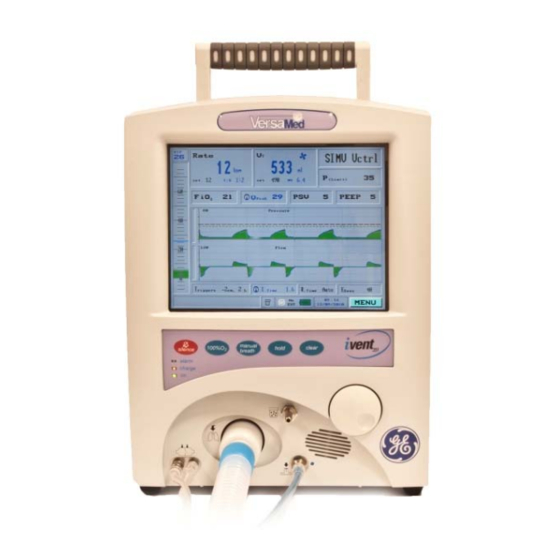
1 Introduction LOOKING AT THE IVENT™201 Figure 1: Front View of the iVent™201 Item Number Description Display Keypad Control Knob Exhalation valve luer inlet Ventilator outlet Sensor line luer inlets Nebulizer outlet... - Page 18 Figure 2: Back View of the iVent™201 Item Number Description Carrying handle Keyboard connector Remote alarm connector External screen connector LAN connector* Do not remove connector cap. This connection port is not in use AC cable clip RS 232 connectors (COM1 and COM2) On/off switch (with cover) High pressure oxygen inlet connector...
-
Page 19: Cautions And Warnings
1 Introduction 4 x Battery pack screws Internal battery handle DC fuse AC fuses DC cord connector Grounding pin AC cord connector Cooling fan CAUTIONS AND WARNINGS CAUTION The iVent 201 is a restricted medical device to be operated by qualified medical personnel under the direction of a qualified medical practitioner Always perform a complete Operation Verification Test (O.V.T.) when... -
Page 20: Symbols And Labels
mandatory. Qualified medical personnel should visually monitor patients on life-support ventilation. Life-threatening conditions may arise that might not activate alarms, To prevent explosion hazard, do not use the ventilator in the presence of flammable anesthetics. Do not cover the iVent 201 while it is in use. - Page 21 1 Introduction Location Label AC Connector AC IN 100-240V 50-60Hz 1.6A 2xT3.15AL (250V) AC Fuses INLET AIR Air Inlet FILTER DO NOT OBSTRUCT COOLING Cooling Fan DO NOT OBSTRUCT Connector DC IN 12-15V 8.5A T15A (250V) DC Fuse Device ID Device Product Ethernet Connector (not...
- Page 22 High Pressure Oxygen Inlet Keyboard Connector Power Pack T15A (250V) Fuse Power Switch Remote Alarm REMOTE Connector ALARM Serial RS-232 Communication Connector...
- Page 23 1 Introduction Power Pack POWER PACK (inside) P/N : 503A0012 Caution: This Power Pack contains a sealed Lead - Acid Battery. Disposal of this unit should be according to Environmental Safety Requirements for Lead-Acid batteries. VersaMed...
-
Page 24: Performance Parameters
PERFORMANCE PARAMETERS Ventilation Component Parameters/ Unit of Accuracy Range Measure Respiratory rate 1-12 1 12-80 2 Inspired Tidal Volume 50-2000 10% Measurement Exhaled Tidal Volume 50-300 10 mL or Measurement +15% whichever is 300-2000 greater +10% Inspiratory Pressure Limit 5 to 80 cmH2O 5 Inspiratory Time... -
Page 25: Specifications
1 Introduction SPECIFICATIONS MONITORED DATA RANGE, RESOLUTION AND ACCURACY The following section describes the various specifications and parameters of the iVent 201. Parameter Range, resolution, accuracy Breath type Range: Type: - Control, assist, patient, sigh Resolution: N/A Accuracy: N/A Respiratory Rate Range: 0 to 150/min Resolution: 1/min Accuracy: 1 for 1 to 12/min... - Page 26 Resolution: 1% Accuracy: 5% Range: 0 to 100% Flow Leak Resolution: 1% Accuracy: 15% Range: 0 to 99 cmH Mean Airway Pressure Resolution: 1 cmH Accuracy: 2 (+ 5 % of reading) cmH Range: 0 to 99.9 cmH O/L/s Resistance (dynamic) Resolution: 0.1 cmH O/L/s...
-
Page 27: Size And Weight
1 Introduction SIZE AND WEIGHT Parameter Height: 13” / 33 cm Width: 9.5” / 24 cm Depth: 10.3” / 26 cm Screen: 8.4” / 21.3 cm diagonal Weight 18.3 lb/8.3 kg (without battery) Battery Weight 6.2lb/2.8kg Extended Battery 10.1 lb / 4.6 kg Weight Overall Weight 24.5 lb/11.1 kg... -
Page 28: Environmental Specifications
ENVIRONMENTAL SPECIFICATIONS Parameter Operating Temperature 0 to +50 °C / +32 to +122 °F Storage Temperature Without battery: -15 to +70 °C / +5 to +158 °F With battery: -15 to +30 °C / +5 to +86 °F Relative Humidity 15 to 95% @ 30 °C / 86 °F Water and Dust IP-54 (Splash proof) -
Page 29: O2 Supply Specifications
1 Introduction O2 SUPPLY SPECIFICATIONS Parameter High Pressure Pressure Range 40 –75psi (2.8-5.1 bar). Warning: The exact oxygen pressure which the iVent 201 uses depends on the version you have. Check the back label (shown in Figure 11) for the pressure levels of your unit. Low Pressure Maximum flow 15L/min or 0.5 psi VENTILATION PERFORMANCE AND CONTROLLED... -
Page 30: Pulse Oximetry Specifications
PULSE OXIMETRY SPECIFICATIONS Oxygen Saturation Range: 0 to 100% Pulse Rate Range: 18-300 pulse par a minute Measurement Wavelengths: Red- 660 nanometers at 3m W nominal Infrared – 910 nanometers at 3m W nominal SpO2 Accuracy: No motion (adult, pediatrics) + 2 digits (70-100%)(+1SD) Motion (adult, pediatrics) -
Page 31: Standards And Safety Requirements
1 Introduction STANDARDS AND SAFETY REQUIREMENTS The iVent 201 meets or exceeds the following international standards: EN/IEC 60601-1 Medical Electrical Equipment – General requirements for safety EN/IEC 60601-1-2 Medical Electrical Equipment - Part 1: General requirements for safety 2. collateral standard: Electromagnetic Compatibility - requirements and tests EN/ IEC 60601-1-6 General requirements for basic safety and essential... - Page 32 DISPLAYED PARAMETERS The following table presents the displayed parameters and indicates whether the displayed values are set, measured or both. Unit of Measure Parameter Rate Ventilation Mode Oxygen Concentration Inspiration to Expiration time ratio I:E ratio Inspiratory Time (I time Sensitivity Values O/LPM (Triggers): Pressure and...
- Page 33 1 Introduction Unit of Measure Parameter Sigh Breath Setting Humidifier Setting (purge cycle) Nebulizer Settings (time) Hr: min * In SW version 19.18.01 estimated leak in adaptive Bi-Level mode is presented in %...
-
Page 34: User Adjustable Alarms
USER ADJUSTABLE ALARMS Value Range Respiratory rate High: 4-80 bpm Low: 1-77 bpm Minute volume High: 1-99 L/min; off Low: 0-60 L/min Inspiratory pressure High: 4-80 cmH Low: 1-77 cmH Apnea 5-120 seconds High: 22-100% Low: 21-99% Leak 0-100% Low Tidal Volume Off or 15%-85% Delivered Volume Limit Reached... -
Page 35: Additional Alarms And Indicators
1 Introduction ADDITIONAL ALARMS AND INDICATORS The following table shows Additional Alarms. Alarms Low O2 Pressure AC Power Disconnect Low Battery Empty Battery Battery Disconnect or Damaged Over Temperature Check Sensor Tube Disconnect Sensor Disconnect Patient Disconnect Service Notice High PEEP Need Cal (Calibration) Patient Circuit Failed SpO2 Patient... - Page 36 WAVEFORMS AND DIAGNOSTICS PACKAGES Pressure, Flow, and Volume Waveforms Software Package includes the following: Real Time Pressure and, Flow Waveforms Waveform History Browsing Trending of Monitored Data Respiratory Diagnostics Software Package Pressure, Flow and Volume Loops ...
-
Page 37: Intended Use
1 Introduction INTENDED USE The iVent™201 MR Conditional is a portable, computer controlled, electrically powered intensive care ventilator intended to provide continuous or intermittent ventilatory support for the care of individuals who require mechanical ventilation. Specifically, the ventilator is applicable for use with adult through pediatric patients, who require invasive or non-invasive assistance via the following general modes of ventilatory support, as prescribed by an attending physician: ... - Page 38 The facility must map and permanently mark the 100 Gauss strength line on the floor with a durable tape. VersaMed Gauss line warning floor label (Versamed P/N 350C0323-01, GE P/N M1218236), shown in Figure 3 below can be used to emphasize the location of the 100 Gauss line.
- Page 39 1 Introduction MR Class MR conditional per ASTM 2503-05 WARNING Use of the ventilator other than as instructed may result in injury to the patient or personnel. Connect the potential equalization pin on the back of the ventilator to the CAUTION ground during battery (DC power) operation Before using the MR suite, remove the green cover and the attached metal...
- Page 40 P/N M1162046 OXYGEN CYLINDER HOLDER, MRI CONDITIONAL P/N M1206571 GCX iVENT 201 ROLL STAND MRI CONDITIONAL P/N M1162044 ROLL STAND AND MOUNTING BRACKET, MRI-CONDITIONAL P/N M1162051 BEDRAIL MOUNTING MECHANISM The iVent 201 was tested with the Magnetom Trio, a Siemens Medical Solution scanner under 3 Tesla, horizontal static magnetic field.
-
Page 41: Mri Conditional Tests Specifications
1 Introduction MRI CONDITIONAL TESTS SPECIFICATIONS The iVent™201 MR conditional has been performed to demonstrate that there are no known hazards in a specified MR environment with specified conditions. The specified MR environment was: Model: Magnetom Trio, Siemens Medical Solutions, Erlangen, Germany, 3 Tesla, horizontal static magnetic field, active shielded Image frequency: 123.192952 MHz... -
Page 43: Setting Up
2 Setting up 2 SETTING UP This chapter contains the following sections: Introduction Page 32 Power Connection Page 32 Oxygen Supply Page 38 Patient Circuit Page 40 Other Connections Page 44 Patient Connection Page 49 Filters Page 49 Operational Case Page 51 The iVentTM201 User Interface Page 51... -
Page 44: Introduction
INTRODUCTION This section shows you how to set up the iVent 201, and includes the following: Connecting to external AC or DC power Using the internal battery Verifying power condition Charging the battery, and proper recharging procedure ... - Page 45 2 Setting up Figure 5: External AC and DC power supply sockets. The AC power cord is connected to the power inlet and fastened with the clip. NOTE To prevent accidental disconnection of the AC power cord, secure it with the cable clip WARNING If the power cord is damaged, worn, or frayed, replace it immediately...
- Page 46 Figure 6: On-Screen Power Status Indicator Icon Icon Name Power State Power When the iVent 201 is connected to an AC power supply, the screen shows a 3-pronged power outlet icon. Power When disconnected from the AC power supply, disconnect the 3-pronged outlet icon is displayed with a red “X”...
-
Page 47: Internal Battery
2 Setting up provided by external batteries may change. To prevent switch-offs from the external battery due to normal fluctuations in DC voltages, the iVent 201 is programmed to average the external DC voltage reading over time. Therefore, if the user disconnects the external battery, the ventilator interprets this as a dying battery and switches off the external DC source for power. - Page 48 be substituted and programmed according to the VersaMed Service Manual and only with the battery specified in those notes Full Recharge Procedure CAUTION “Low Battery” or “Empty Battery” alarm appears, the internal battery must y recharged, as described below Continued usage of the battery after the “Empty Battery” alarm appears may disable the battery’s charging capability and/or lead to battery failure.
- Page 49 2 Setting up NOTE If Extended battery is in use, charge the unit for at least 24 hours. If after a full recharge, the battery indicator fails to reach Full, or a Low or Empty Battery alarm displays, then the battery pack must be replaced. Battery Pack Replacement The following procedures explain how to replace the battery pack.
-
Page 50: Oxygen Supply
Charge the battery by following the instructions in Full Recharge Procedure, page 36. OXYGEN SUPPLY The iVent 201 can use medical-grade oxygen from either A high-pressure source such as a central supply system or cylinder at 40-75 psi (2.8-5.1 bar). WARNING The exact oxygen pressure which the iVent 201 requires when... -
Page 51: Low Pressure Oxygen Supply
2 Setting up Figure 11: The Oxygen Inlet Connector CAUTION When using the iVent 201 with a pressurized oxygen supply, the accuracy of the oxygen concentration should be verified periodically with an external calibrated oxygen analyzer LOW PRESSURE OXYGEN SUPPLY Connecting a low pressure O2 supply Adapter requires a low pressure O2 filter/adapter, fitted with a 22mm female port. -
Page 52: Patient Circuit
Figure 12: Low Pressure O Supply Adapter and Filter Installed Be sure that the Low +M or Low option is selected under Oxygen Supply (Pressure) in the Advanced Settings menu (See page 91). CAUTION Do not attempt to use the FiO2 option above 60% when using a low pressure oxygen supply When not using a low pressure O2 supply, the Low Pressure O2 Filter must NOT be used, as the 22mm port is easily blocked. -
Page 53: Disposable Patient Circuit
2 Setting up DISPOSABLE PATIENT CIRCUIT The disposable patient circuit consists of an inspiratory limb with a connector at one end of corrugated tubing, and a one-way valve connected to the Patient Wye at the other end (Figure 13). Figure 13: Patient Circuit Connections (Breathing Circuit) The Patient Wye contains a flow sensor which is connected by two sensor tubes to the luer connectors on front of the ventilator. -
Page 54: Dual Limb Patient Circuit
To connect a reusable patient circuit: Twist the knurled connector of the Inspiratory limb onto the Ventilator outlet. The connector should fit snugly. Connect the Flow Sensor tubing (the clear tubes) to their connectors. Ensure correct connection of the Male and Female luer connectors on the flow sensor tubing. - Page 55 2 Setting up Figure 14: Exhalation Valve Positions The Exhalation valve is now connected and ready to use. The next step involves installing the tubing to the ventilator. To install the patient circuit: Assemble the PEEP control tube by connecting one end to the barb fitting of the exhalation valve and the other end to the barb fitting of the reusable Luer fitting.
-
Page 56: Circuit Resistance
CIRCUIT RESISTANCE It is important to check the inspiratory and expiratory resistance specification of the patient circuits used with the iVent 201 ventilator to ensure they do not exceed the following limits when adding attachments or other components or subassemblies to the breathing circuit: ... - Page 57 2 Setting up Connect the one-way valve to one end of a 1-2’ length of 22mm corrugated tubing. Connect the other end of the tubing to the ventilator outlet. Fasten the one- way valve to the humidifier inlet. Be sure the directional arrow on the valve is pointing towards the patient end of the circuit.
-
Page 58: Pneumatic Nebulizer
lowest point of the Inspiratory Limb is highly recommended. Follow the humidifier manufacturer’s instructions for the operation of the humidifier. If a heated wire circuit is required, use the VersaMed inlet equipment (Patient Wye with one-way valve and exhalation valve. Replace the VersaMed inspiratory tubing with the heated wire tubing. - Page 59 2 Setting up pediatric patients in hospital, hospital types facilities, mobile/ transport functions, and home environments. A pulse oximeter can be connected to the iVent 201 ventilator allowing the operator to continuously monitor patient’s oxygenation saturation on the iVent 201 screen. WARNING Use only Nonin manufactured pulse oximeter sensors.
- Page 60 Figure 19: Pulse Oximeter Sensor At the rear panel of the iVent 201 device, connect the following: The Keyboard connector to the Keyboard port. The RS-232 connector to the RS-232 port (COM1 or COM2), located on the right side of the device. (Figure 20). Keyboard Connector Remote Alarm...
-
Page 61: Remote Alarm
2 Setting up REMOTE ALARM The iVent 201 can be connected to a remote alarm system via the Remote Alarm Connection port on the back panel shown in Figure 20. Using Normally Opened (NO) or Normally Closed (NC) signals, this connection port allows alarm signal activation in locations remote from the ventilator triggered by ventilator alarm conditions. -
Page 62: Air Inlet Filter
AIR INLET FILTER The air inlet filter (part no. M1161007 )screens out particulate matter from ambient air (Figure 21). Figure 21: Air Inlet Filter WARNING Failure to use an air inlet filter may result in severe damage to the internal components of the iVent 201. -
Page 63: Operational Case
2 Setting up The CBRN filter fits into the iVent 201 via an optional air inlet adapter (item M1161967). Remove the air inlet filter from the iVent 201 by turning it counterclockwise. Then fasten the air inlet adapter to the CBRN filter by twisting it on clockwise. -
Page 64: Controls And Power Up
CONTROLS AND POWER UP THE FRONT PANEL Located above and to the right of the ventilator outlet, is the rotational Control Knob, which allows control of and access to all the ventilator functions via the LCD screen. Turn the knob to change a value, or navigate through a menu screen or through a list of choices. -
Page 65: Manual Breath
2 Setting up Figure 25: Status Window After Alarm Has Been Silenced Manual Breath Manual Breath delivers a single breath at the set tidal volume or pressure. In CPAP/PSV ventilation mode, where there is no definition for machine breath, the Manual Breath is set according to the default volume control for the specified patient weight chosen at startup. -
Page 66: The Screen
The amber charge LED lights to indicate that the iVent 201 is connected to external power. The green on LED indicates that the power is switched on. The Screen The LCD screen is organized to allow rapid access to the ventilator’s functions. The monitoring or control of any critical parameter is performed with ease. - Page 67 2 Setting up Figure 26: The Main Screen If a pulse oximeter is connected to the iVent 201 the SpO2 levels and Heart rate are displayed on the lower right side of the screen (Figure 27). Figure 27: The Main Screen With the Pulse Oximetry Monitoring Window...
- Page 68 Notes:...
-
Page 69: Operating The Ivent Tm 201 - Setting Modes And Parameters
3 Operating the iVentTM201 – Setting Modes and Parameters 3 OPERATING THE IVENT 201 – SETTING MODES AND PARAMETERS This chapter contains the following sections: Introduction Page 59 Operation of the iVentTM201 Page 59 Common Parameters Page 64... -
Page 71: Introduction
3 Operating the iVentTM201 – Setting Modes and Parameters INTRODUCTION The iVent 201 offers advanced capabilities for adjusting ventilation parameters for each mode. In this section you learn how to: Start the ventilator Choosing a patient weight Test the patient circuit ... - Page 72 NOTE Parameters for all the iVent 201’s possible ventilation modes are set when you choose a patient weight upon startup. For a view of the default parameters according to weight, refer to Table 1: Default Start Parameters for Volume Ventilation for 10 kg to 70 kg through Table 4, page 107. The default selection for patient weight range for the iVent 201 is 70+kg.
-
Page 73: Standby And Patient Ventilation
3 Operating the iVentTM201 – Setting Modes and Parameters Figure 29: The Initial O.V.T Pop-Up Window 3. Follow the instructions on the screen. Use the plastic caps to seal off the following: The patient Wye sensor, and The exhalation valve 4. -
Page 74: Changing Ventilation Mode
Return to the Main screen, rotate the Control Knob until the Start option is selected, then press the Control Knob. To return the ventilator to Standby mode: Return to the Main screen, turn the Control Knob to select the Mode Selection option on the top right of the LCD display, and press the Control Knob. - Page 75 3 Operating the iVentTM201 – Setting Modes and Parameters Figure 31: The Ventilation Modes Selection Pop-Up Menu Window NOTE Depending on which iVent 201 model you have purchased, not every mode may be available. Turning the Control Knob moves the selected bar through the choices. When the required mode is selected, press the knob to accept it.
-
Page 76: Common Parameters
Figure 32: Pressure Control Option Selected Press the knob to accept the selection. The SIMV Pressure Control Parameters screen appears (Figure 33). Figure 33: The SIMV Pressure Control Parameters Screen Note that Accept is automatically selected, which makes it possible to accept the default parameters immediately and go directly into patient ventilation. -
Page 77: Changing Ventilation Paramters - Overview
3 Operating the iVentTM201 – Setting Modes and Parameters Tidal volume Pressure limit Oxygen level Peak flow Pressure support PEEP Triggers Inspiratory time Rise Time Flow Termination – Exhale sensitivity (Essens) CHANGING VENTILATION PARAMTERS –... -
Page 78: The Selection Interface
5. Press the knob again to save the setting. You are returned to the Parameters screen. 6. Continue through the other parameter options, and choose and change until you have set all the values you want. Once you have finished, select Accept at the bottom of the screen. -
Page 79: Adjusting The Breath Rate
3 Operating the iVentTM201 – Setting Modes and Parameters The chosen values are not operational until you confirm your selection by pressing the Control Knob, which takes you back to the Main screen. The new value(s) you have selected are shown in black. NOTE To abort the selection process and return the parameter to the previously chosen value, press the Clear button. - Page 80 Figure 36: Respiratory Rate Selected on the Mode Parameter Screen Press the Control Knob to display the Set Rate pop-up window (Figure 37). Figure 37: The Set Rate Pop-Up Window Turn the Control Knob to change the rate, measured in breaths per minute.
-
Page 81: Adjusting The Tidal Volume
3 Operating the iVentTM201 – Setting Modes and Parameters ADJUSTING THE TIDAL VOLUME The Tidal volume is the amount of air inhaled and exhaled in a breath and can be adjusted during the ventilation. To adjust the tidal volume: Select the Tidal Volume (or in Pressure Control select Volume Limit) setting from the top middle section of the Main screen (Figure 38): Figure 38: Tidal Volume Selected on the Main Screen Or select Tidal Volume in the Parameters screen (Figure 39):... -
Page 82: Breath Types
Figure 40: The Tidal Volume Pop Up Window Turn the Control Knob to change the Tidal Volume settings. After setting a new value press the Control Knob to confirm and accept the settings. Changing the Tidal Volume affects the Mandatory Minute Volume. If a Manual Peak Flow is set and does not deliver the set volume in the allotted inspiratory time, then the display flashes. -
Page 83: Adjusting Pressure
3 Operating the iVentTM201 – Setting Modes and Parameters Pink Fan Mandatory Assist Breath (patient initiated) - the iVent 201 has responded to patient initiation by delivering a breath. Blue Fan Mandatory Ventilator Breath (ventilator initiated) - the iVent 201 has delivered a breath without patient initiation. - Page 84 Figure 42: Pressure Limit Selected on the Main Screen Or select the Pressure option in the Mode Parameters screen (Figure 43): Figure 43: Pressure Limit Selected on the Mode Parameters Screen 2. Press the Control-Knob to display the Set Pressure pop-up window (Figure 44).
-
Page 85: Adjusting Fio2
3 Operating the iVentTM201 – Setting Modes and Parameters 3. Turn the Control Knob to choose the required numeric pressure value. The high pressure alarm is adjusted automatically to the value PLimit + 5 cmH2O. It can also be set to any required value using the Alarm menu. For more information see page 148.) 4. -
Page 86: Adjusting Peak Flow
Figure 46: FiO2 Selected on the Mode Screen Press the Control Knob to display the FiO2 pop-up window (Figure 47). Figure 47: The FiO2 Pop Up Window Turn the Control Knob to adjust the FiO2 level. The range is 21% to 100%. Press the Control Knob to confirm and accept the settings. - Page 87 3 Operating the iVentTM201 – Setting Modes and Parameters Figure 48: Peak Flow Selected on the Main Screen Or select the Peak Flow on the Mode Parameters screen (Figure 49): Figure 49: Peak Flow Selected on the Mode Parameters Screen Press the Control Knob to display the Peak Flow pop-up window (Figure 50).
-
Page 88: Adjusting Pressure Support Ventelation
Figure 50: The Set Flow Pop-Up Window Turn the Control Knob to change the peak flow value. To set the flow to Adaptive Flow™, turn the Control Knob counterclockwise until Adapt is displayed. Press the Control Knob to confirm and accept the settings. If Adaptive Flow™... - Page 89 3 Operating the iVentTM201 – Setting Modes and Parameters Figure 53: PSV Selected on the Main Screen Or select the PSV option in the Mode Parameters screen (Figure 54): Figure 54: PSV Selected on the Mode Screen Press the Control Knob. The PSV pop-up window appears: Figure 55: The PSV Pop-up Window Turn the Control Knob to adjust the PSV level.
-
Page 90: Adjusting Peep
NOTE The PSV value cannot be set to a value greater than P(Limit) – PEEP or a maximum value of 60 cmH2O. Press the Control Knob to confirm and accept the settings ADJUSTING PEEP The PEEP level of the patient is adjusted to a set value during the ventilation. To adjust the PEEP: Select PEEP from the second row on the Main screen (Figure 56): Figure 56: PEEP Selected on the Main Screen... -
Page 91: Adjusting Trigger Sensitivity
3 Operating the iVentTM201 – Setting Modes and Parameters Figure 58: PEEP Pop-Up Window Turn the Control Knob to adjust the PEEP level. The Inspiratory Pressure limit above PEEP is shown at the bottom of the Setting pop-up window as adjustments are made. -
Page 92: Adjusting Inspiratory Time
Figure 60: Triggers Selected on the Mode Parameters Screen Press the Control Knob. Two sliding numeric gauges appear (Figure 61) Figure 61: The Triggers Slider Gauges Dial the Control Knob to select the required pressure value. Press the Control Knob to confirm the pressure settings and select the Flow gauge. - Page 93 3 Operating the iVentTM201 – Setting Modes and Parameters Figure 62: Inspiratory Time Selected on the Main Screen Or select the Inspiratory Time option on the Mode Parameters screen (Figure 63): Figure 63: Inspiratory Time Selected on the Mode Parameters Screen Press the Control Knob.
-
Page 94: Adjusting Rise Time
3. Turn the Control Knob to change the Inspiratory Time. Notice that the I:E ratio is calculated as you adjust the value. 4. To return to Adaptive I. Time™, turn the Control Knob counterclockwise until Adapt appears. 5. Press the Control Knob to confirm and accept the settings. If Adaptive Inspiratory Time is selected a blue icon with black circled A is displayed on the Main screen (Figure 66). - Page 95 3 Operating the iVentTM201 – Setting Modes and Parameters Figure 67: Rise Time Selected on the Main Screen Or select the Rise Time option in the Mode Parameters screen (Figure 68): Figure 68: Rise Time Selected on the Mode Parameters Screen NOTE The Rise Time option is located in the top left of the Mode Parameters screen for Adaptive Bi-Level mode.
-
Page 96: Adjusting Flow Termination (Esens)
Figure 69: The Rise Time Pop Up Window In Adaptive Bi-Level ventilation mode the rise time can be adjusted between 0.1 and 1.5 seconds (Figure 70). Figure 70: The Rise Time pop up window in Adaptive Bi-level ventilation mode 3. Turn the Control Knob to select the required value. 4. - Page 97 3 Operating the iVentTM201 – Setting Modes and Parameters Figure 71: Esens Selected on the Main Screen Or select the Esens option in the Mode Parameters screen (Figure 72): Figure 72: The Esens Option Selected on the Mode Parameters Screen Press the Control Knob.
- Page 98 Notes:...
-
Page 99: The Main Menu
4 The Main Menu 4 THE MAIN MENU This chapter contains the following sections: Introduction Page 89 Navigating the Main Menu Page 89 Alarm Settings Page 90 Advanced Settings Page 91 Restore Default Settings Page 105 Show Graphs Page 108 Show Trends Page 112 Show Loops... -
Page 101: Introduction
4 The Main Menu INTRODUCTION The Main Menu controls many of the iVent 201’s key settings and functions. In this section you learn how to use the Main Menu in order to: Change the Alarm Settings Change Advanced Settings ... -
Page 102: Alarm Settings
Figure 74: The Menu Option Selected on the Main Screen Press the Control Knob and the Main Menu pop-up window appears (Figure 75): Figure 75: The Main Menu Turn the Control Knob to select a function. Press the Control Knob to open the function you have selected. To return to the Main Screen from anywhere in the Main Menu either: ... -
Page 103: Advanced Settings
4 The Main Menu ADVANCED SETTINGS The Advanced Settings screen allows you to switch or adjust several patient and ventilator parameters, including: Sigh breath (off/interval) Easy Exhale™ (on/off) Oxygen supply (None/ Low/ Low +M/ High Adaptive Peak Flow (Off/Low/Mid/High) ... - Page 104 The Sigh Breath volume is 1.5 times the set tidal volume. To adjust the Sigh Breath: From the Main screen select Menu – Advance Setting. The Advance Settings screen appears. In the Advance Settings screen select Sigh Breath Every. The current interval is shown in the right column of the screen (Figure 77).
-
Page 105: Easy Exhale
4 The Main Menu EASY EXHALE™ Easy Exhale™ is an advanced feature when PEEP>0 is selected. It is designed to shorten expiratory time and reduce risk of auto-PEEP (For more information, see Page 137.) The default setting for Easy Exhale is on. Use the Advanced Settings menu to turn Easy Exhale off or on. -
Page 106: Oxygen Supply
OXYGEN SUPPLY You set the type of oxygen supply used with the iVent 201 from the Advanced Settings menu. There are 4 available options: High Low + Monitoring None For more about each option, see description below. To set the oxygen supply pressure: From the Main screen select Menu –... -
Page 107: High Option
4 The Main Menu Figure 82: The Oxygen Supply Pop-Up Window Turn the Control Knob to select the appropriate option. Press to accept the option. Press the Control Knob to confirm and accept the settings. NOTE The 02 Sensor continues to measure the O2 levels, even when, in some options, these measurements are not displayed, and the O2 alarms are not activated. -
Page 108: Alarm Messages
Alarm Messages If the O2 sensor fails, one of the following alarm messages is displayed on the iVent 201 screen. The alarm message depends on whether the iVent device serial number is lower or higher than 15000. Alarm Message for Serial Number 12000 -14999 NOTE You cannot close this alarm using the Clear button. -
Page 109: Low + Monitoring Option
4 The Main Menu Select OK to close the alarm pop-up window. The FiO2 setting is displayed with a yellow background. You can change the FiO2 setting within a range from 21% to 100%. A small red icon is displayed on the left corner of the status bar, showing O2 Sensor (Figure 84) When the O2 sensor failure is corrected, this icon changes to green and can be cleared. -
Page 110: None Option
disabled, such as Low O2, High O2, and O2 sensor failed. After selecting the Low option, a Warning pop-up window is displayed (Figure 86): Figure 86: Low Option Warning The alarm settings and readings are disabled, and the FiO2 field displays - - If the O2 sensor fails, no alarm is displayed. -
Page 111: Humidifier Setting
4 The Main Menu Figure 87: Adaptive Peak Flow Chosen NOTE The factory default value is High. VersaMed recommends that you use High. HUMIDIFIER SETTING When a Humidifier is connected (See page 44) moisture tends to cluster at the sensor tubes. To prevent this excess moisture, the iVent 201 periodically sends a burst of air through the sensor tubes. -
Page 112: Pulse Oximetry
Figure 88: Humidifier Setting Selected Press the Control Knob. A pop-up window appears with the values Heated, HME, and OFF. Turn the dial of the Control Knob to select the setting you want. Press the Control Knob to confirm and accept the settings NOTE Purge is performed every minute the Nebulizer is activated. - Page 113 4 The Main Menu Inspect the sensor application site at least every 6-8 hours to ensure skin integrity. Patient sensitivity may vary due to medical status or skin condition. Discontinue use of adhesive tape strips if the patient exhibits an allergic reaction to the adhesive material.
-
Page 114: Pneumatic Nebulizer
Turn the dial of the Control Knob to select the option you want. Press the Control Knob to confirm and accept the settings. To disable the Pulse Oximetry function from the Main screen select and press Menu – Advance Setting – SpO2 enabled – Disable. For information regarding the Pulse Oximetry screen operation see page 120. -
Page 115: Set Time And Date
4 The Main Menu Figure 92: Nebulizer Pop Up Window NOTE The Nebulizer option is active only during ventilation. You can however, also set the Nebulizer in Standby Mode. It is activated after you start ventilation. The nebulizer is activated only when you set the Oxygen Supply to High option (See page 38). - Page 116 Figure 93: Set Time and Date Chosen Press the Control Knob. The Set Time and Date pop-up window appears, showing the currently set time, with the hour (in 24-hour mode) selected (Figure 94). Figure 94: The Set Time and Date Pop-Up Window To change the hour, make sure the hour is selected, then press the Control Knob.
-
Page 117: Restore Default Settings
4 The Main Menu Close the Advanced Settings screen and verify that the time and date has changed on the Main screen clock, which is situated on the lower right of the screen. RESTORE DEFAULT SETTINGS To clear ALL settings and return the iVent 201 to its default startup state, use Restore Defaults. -
Page 118: Default Parameters Settings
Figure 96: The Restore Defaults Warning Pop-Up Window Turn the Control Knob to Confirm and press. The Restore Default Params pop-up window appears, and instructs you to select a Default Weight. Choose a Default Weight by dialing the Control Knob. The factory default is 70+kg. Press the Control Knob again. - Page 119 4 The Main Menu Table 2: Alarm Default Parameters for Volume Ventilation for 10 kg to 70 kg Alarm Parameter Weight (kg) High Pressure (cmH High Rate (bpm) Low Rate (bpm) High Min Vol. (LPM) Low Min Vol. (LPM) Table 3: Default Alarms Settings Low Pressure 5 cmH Apnea Time...
-
Page 120: Show Graphs
Table 5: Alarm Default Parameters for Pressure Ventilation for 10 to 70 kg Alarm Weight (kg) Parameter Volume Limit 1000 1100 1200 Reached, mL High Pressure 30 for all weights (cmH2O) All other alarm default parameters are the same as for Volume Ventilation (See Table 1, Table 2). - Page 121 4 The Main Menu To browse the waveforms: 1. On the Main screen choose either the Pressure waveform or the Flow waveform by rotating the dial so that the Select bar of either is chosen (Figure 97). Figure 97: The Flow Waveform Selected Press the Control Knob to display the Graph Choice bar: From the Graph Choice bar, select Browse with the Control Knob, and press the Control Knob.
-
Page 122: Select Range
The waveform display pauses at that moment, although it continues to record and the results are stored. Turn the dial counterclockwise, and the time coordinate cursor moves backward along the time axis. Turn the dial clockwise and the time coordinate cursor moves forward along the time axis. NOTE The Select option on the bar is not active. - Page 123 4 The Main Menu Figure 100: Pressure Ranges If you select the Pressure graph, the choices are 80, 60, 40 cmH2O and Auto (the default). Move the dial to choose the required value, and press the dial to accept the new range. If you select the Flow graph, the choices are 210, 150, 120, 90, 60 L/minute and Auto (the default).
-
Page 124: Show Trends
SHOW TRENDS You can view trends in any of 14 parameters and calculated patient response characteristics over a period up to 72 hours. All of the following can be displayed using the Show Trends menu: Peak Flow Peak Pressure ... - Page 125 4 The Main Menu If Show Trends is viewed while the ventilator is in Standby Mode, three Trends (default Trends shown are Peak Flow, Peak Pressure, and Minute Volume) appear in a pop-up window on the right side of the screen (Figure 103): Figure 103: Trends Pop-Up Window in Standby Mode If the ventilator is in operation, the three displayed Trends appear in a window...
-
Page 126: Selecting Trends To Display
SELECTING TRENDS TO DISPLAY To select trends you want to view: 1. Turn the Control Knob to the Select bar of the Trend graph you want to change (Figure 105). Figure 105: The Minute Volume Graph is Selected Press the Control Knob. The Trends Choice window appears. Turn the Control Knob to Select, then press. -
Page 127: Browsing Trends
4 The Main Menu Figure 107: I:E Ratio Displayed You can continue to choose alternative Trends to view by selecting the Select bar of each graph and then use the Trends Choice option to make your choice. BROWSING TRENDS You can recall trend information over a 72-hour period using the Browse feature. To browse the trends: 1. - Page 128 A small blue selected option marked Browse appears, with the time and graph's cursor in center of the viewable data (Figure 109) Figure 109: The Browse Trends Pop-Up Window Rotating the dial clockwise moves the time cursor indicator forward. Rotating the dial counterclockwise moves the indicator backwards along the timeline.
-
Page 129: Show Loops
4 The Main Menu The Zoom popup window appears. Turning the Control Knob adjusts the scale of the time shown, to enable viewing of larger or smaller-scale trends over time. To switch back to the default Pressure/Flow graph view: Select and press the Menu option in the Main screen to view the Main Menu pop-up window. - Page 130 Figure 112: The Show Loops Pop-Up Window Select any of the loops, or all three. The loops appear on the right side of the Main screen. A sample of a Pressure/Volume Loop is displayed below (Figure 113): Figure 113: A Pressure/Volume Loop Each new loop is drawn in blue, and turns to dark gray once the inspiratory cycle begins.
-
Page 131: Show Mechanics
4 The Main Menu Figure 114: One Loop Loops Screen You can use these to freeze a single loop on the display for purposes of clinical comparison. NOTE This feature is only possible when one loop is displayed To freeze a loop: Rotate the Control Knob to select the Freeze button, then press. -
Page 132: Pulse Oximetry Screen
Figure 115: Show Mechanics Selected Press the Control Knob. The right section of the screen shows the selection of numeric values: Figure 116: The Mechanics Pop-Up Window PULSE OXIMETRY SCREEN The Pulse Oximetry screen (Figure 117) displays the following measurements:... - Page 133 4 The Main Menu SpO2 – displays the oxygen saturation percent in the patient blood. This measurement is available in numeric format on all screens. Heart Rate – displays the heart rate (in bpm) in numeric format. Figure 117: The Pulse Oximetry Screen on the Main Screen The upper and the lower alarm limits settings are displayed in black on the right side of the screen.
-
Page 134: Pulse Oximetery Alarms
Figure 119: .Pulse Oximetry Screen in Standby mode To close the Pulse Oximetry screen: In the Pulse Oximetry screen select Close. To re-open the Pulse Oximetry screen in standby mode: From the Main menu select Menu – Pulse Oximetry. PULSE OXIMETERY ALARMS The following alarms are the pulse oximetry alarms. -
Page 135: Show Log Book
4 The Main Menu Figure 120: SpO2 Alarms Settings Screen Use the Control Knob to select the following alarms: Pulse (heart rate) SpO2 (SpO2 level). The top of the slider is selected bright blue. Turn the Control Knob to adjust the alarm upper limit, and press the Control Knob for acceptance. -
Page 136: Display
Figure 121: Show Log Book Selected on the Main Menu Press the Control Knob. A bright blue screen appears, which shows in chronological order, each event stamped with the date and time. Rotating the dial counterclockwise moves the selected bar backwards for the log of events. - Page 137 4 The Main Menu Figure 122: The Monitoring Display The Monitoring display (Figure 122) is designed for optimal readability, and shows yellow letters over a black screen with yellow numerals showing key ventilation parameters. The Pulse SpO2 pop-up window can be viewed on the Monitor display. To display the SpO2 pop-up window on the monitoring screens select and press the SPO2 option on the lower left side of the screen.
- Page 138 Figure 124: The Home Care Display The pulse SpO2 window can be viewed on the Monitor display. To display the SpO2 pop-up window on the monitoring screens select and press the SPO2 option on the lower left side of the screen.: The SpO2 pop-up window appears on right side of the screen (Figure 125).
-
Page 139: 127
4 The Main Menu The Home Care display shows the Mode, the Exhale Volume and the Total Rate. It is designed primarily for the simplest kind of monitoring. If you want to change settings or view ventilator information, proceed to the Main menu display. To switch to any display: Select and press the Menu option on the Main screen to view the Main Menu. - Page 140 Notes:...
-
Page 141: Adaptive Bi-Level
5 Adaptive Bi-Level 5 ADAPTIVE BI-LEVEL This chapter contains the following sections: Introduction Page 131 About Adaptive Bi-Level Page 131 Guide to Adaptive Bi-Level Page 131 Indications and Warnings Page 132 Setup Page 132 Adjusting Adaptive Bi-Level Parameters Page 134 Adaptive Bi-Level Window Page 135 Easy Exhale... -
Page 143: Introduction
5 Adaptive Bi-Level INTRODUCTION In this section the following is discussed: The fundamentals of Adaptive Bi-Level mode Which patients indicate for Adaptive Bi-Level mode How to set up the ventilator for A-B How to resolve patient-ventilator asynchrony ABOUT ADAPTIVE BI-LEVEL In VersaMed’s Adaptive Bi-Level mode the iVent 201 can accommodate high... -
Page 144: Indications And Warnings
INDICATIONS AND WARNINGS INDICATIONS Adaptive Bi-Level is indicated for patients who exhibit clinically appropriate conditions for facemask ventilation. Such patients include those with acute or chronic respiratory insufficiency secondary to acute exacerbation of COPD; hypercapnic acute respiratory failure, or decompensated heart failure. WARNINGS WARNING Patients exhibiting an altered level of consciousness requiring... - Page 145 5 Adaptive Bi-Level Accept or adjust the parameters on the pop-up window. The factory default settings are displayed below (Table 6): Table 6: Adaptive Bi-Level Default Settings Respiratory Rate = 8 bpm IPAP = 10 cmH Easy Exhale™ = On EPAP = 5 cmH Rise Time...
-
Page 146: Adaptive Bi-Level Alarm Settings
ADAPTIVE BI-LEVEL ALARM SETTINGS The Default Alarm Settings for Adaptive Bi-Level are provided below (Table 7): Table 7: Adaptive Bi-Level Default Alarm Settings Rate Default for High Rate is Off Default for Low Rate is 6 Minute Volume Default for Low Minute Volume set to 0 Default for High Minute Volume is based on weight Pressure Default for High Pressure is 20... -
Page 147: Adaptive Bi-Level Window
5 Adaptive Bi-Level Figure 127: Adaptive Bi-Level Mode Parameters The ranges for Adaptive Bi-Level parameters are as follows: Table 8: Adaptive Bi-Level Parameters’ Range Rate 1 to 80 bpm 21% to 100% Rise Time 0.1 to 1.5 sec Note: Rise time cannot exceed inspiration time. IPAP 7 to 60 cmH O;... - Page 148 Figure 128: Adaptive Bi-Level Mode The Vte display shows the estimated Tidal Volume delivered to the patient calculated using the measured flow leak during EPAP. An estimated Leak is shown below the Tidal Volume field of the display. The Leak Estimate value is measured in lpm (See Figure 129) Figure 129: Leak Estimated Value in LPM In SW version 19.18.01 estimated leak in adaptive Bi-Level mode is presented in % (See Figure 130).
-
Page 149: Easy Exhale
5 Adaptive Bi-Level EASY EXHALE Easy Exhale is an advanced feature of the iVent 201, minimizing the imposed exhalation valve resistance when PEEP > 0 is selected. By minimizing the exhalation valve resistance, we ensure as short exhalation time as possible thus reducing the risk of auto-PEEP. -
Page 150: Non-Triggered Breaths (Inspiratory Trigger Failure)
NON-TRIGGERED BREATHS (INSPIRATORY TRIGGER FAILURE) Detection - Failure to trigger the ventilator is detected by patient dysynchrony with mechanical breaths. These are apparent as spontaneous efforts, on the flow waveform, which do not result in a rise in pressure on the pressure waveform. Intervention - Make sure that the enclosed volume of the facemask is not too large, or that the facemask is not poorly applied (see section under excessive leak). - Page 151 5 Adaptive Bi-Level Exclusion – Re-evaluate the patient's clinical status for causes of high respiratory drive to exclude premature I:E cycling and manage appropriately. Intervention – Lower the percent peak flow termination (Esens) and/or decrease the rise time. Use the waveform package to visualize waveforms and prolong the I-time until a visually detectable inspiratory flow termination pattern appears prior to pressure release.
-
Page 153: Alarms
6 Alarms 6 ALARMS This chapter contains the following sections: Introduction Page 143 How Alarms Work Page 143 Alarm settings Page 144 Guide to Alarm Definitions and Priorities Page 158 Alarms Test Page 167 The Sensor Failure Alarm Page 169 Patient Disconnect Alarm Page 170 Patient Circuit Failed Alarm... -
Page 155: Introduction
6 Alarms INTRODUCTION In this section you will learn how to: Quickly respond to iVent 201 alarms Determine and select optimal alarm settings Set alarm parameters and perform troubleshooting Perform Alarm tests The iVent 201 operates when the sensor disconnect alarm is activated or when it senses patient disconnection HOW ALARMS WORK As soon as the iVent... -
Page 156: Alarm Settings
Press the Clear button on the keypad. This silences the alarm and minimizes the alarm pop-up window. If the condition which caused the alarm is not resolved, the minimized alarm appears red and is labeled with a text message that describes the alarm condition. After 30 seconds, the alarm pop-up window maximizes and sounds an audible alert. -
Page 157: Changing Individual Alarm Settings
6 Alarms High and Low O2 This alarm is updated automatically when setting the FiO2 parameter and can also be adjusted from the Alarm Settings screen Leak % NOTE For the Pulse Oximetry related alarms see page 122 The following alarm values are configurable: ... -
Page 158: Setting The Respiratory Rate Alarm
Figure 133: The Alarm Settings Screen The first Alarm Settings screen presents six slide indicators that control the range of values for triggering alarms. Some of these Alarm Conditions have a high and a low value (Rate, Minute Value, Pressure, FiO2), while Apnea accepts only a time value, and Leak a percentage value. -
Page 159: Setting The Minute Volume Alarm
6 Alarms Figure 134: The Respiratory Rate Alarm Slider Selected Press the Control Knob to change the alarm setting for the Respiratory Rate. The top of the slider is selected in bright blue. Turn the dial to adjust the alarm rate for the upper limit in Breaths per Minute. Note that if you attempt to adjust the upper limit of the alarm rate below the currently- selected lower limit, you push the lower limit down. -
Page 160: Setting The Pressure Alarm
Figure 135: The Minute Volume Alarm Slider Selected 4. Press the Control Knob to change the alarm settings for the Minute Volume. 5. The top of the slider is selected bright blue. Turn the dial to adjust the alarm for the upper limit in liters per minute. Notice if you attempt to adjust the upper limit of the alarm below the currently-selected lower limit, you push the lower limit down. -
Page 161: Setting The Apnea Time Alarm
6 Alarms Figure 136: The Pressure Alarm Slider Selected Press the Control Knob to change the alarm settings for the Pressure. The top of the slider is selected bright blue. Dial the knob to adjust the alarm for the upper limit in cmH2O up or down. Note that if you attempt to adjust the upper limit of the alarm below the currently-selected lower limit, you push the lower limit down. -
Page 162: Setting The Fio2 Alarm
Figure 137: The Apnea Time Alarm Slider Selected Press the Control Knob to change alarm setting for the Apnea Time. Dial the Control Knob to select a time between the minimum and maximum ranges. Press the Control Knob to confirm the settings. The Alarm Setting screen is re-displayed. -
Page 163: Setting The Leak Alarm
6 Alarms To change the FiO2 alarm, press the Control Knob. The top of the slider is selected bright blue. Turn the dial to adjust the alarm rate for the upper FiO2 percentage limit, from 21% to 100%, up or down. Note that if you attempt to adjust the upper limit of the alarm below the currently-selected lower limit, you push the lower limit down. -
Page 164: Auto Settings
AUTO SETTINGS The Auto Settings feature sets all the alarms in the Alarm Settings option to suit the currently measured ventilation parameters for the patient. By selecting Auto Settings the measured values for each parameter in the Alarm Settings window with the appropriate limits for those parameters are displayed. -
Page 165: Alarm Options
6 Alarms ALARM OPTIONS The Alarm Options menu allows you to: Set the alarm volume (loudness) Enable or disable the Inverse I:E Ratio alarm Adjust or disable the Low Tidal Volume alarm Enable or disable the Patient Circuit Disconnect alarm To access the Alarm Options menu: 1. -
Page 166: Setting The Alarm Volume
Setting the Alarm Volume NOTE The Alarm volume default is level 8. To set the alarm volume: From the screen select Menu – Alarm Setting - Options. On the Alarm Options screen, select the first option Alarm Volume Level. Press the Control Knob to display the Alarm Volume pop-up window (Figure 143). -
Page 167: Setting The Tidal Volume Not Delivered Alarm
6 Alarms 3. Press the knob. An ON/OFF selection pop up window appears (Figure 144). Figure 144: The Inverse I:E Ratio Alarm Selection Menu Pop-Up Window 4. Turn the dial to select ON or OFF. 5. Press the dial to accept and confirm the settings. 6. -
Page 168: Disabling Or Enabling The Patient Circuit Disconnect Alarm
Figure 145: The Low Tidal Volume Alarm Range Pop-Up Window Turn the Control Knob to adjust the percentage between 0% (Off) and 85%. Press the dial to confirm the settings. You are returned to the Alarm Settings screen. Dial and select Accept to accept the Alarm Options settings. - Page 169 6 Alarms Figure 146: The Patient Circuit Disconnect Alarm Pop-Up Window Turn the knob to select ON or OFF. If you select OFF, a warning pop-up window appears (Figure 147): Figure 147: The Patient Circuit Disconnect Alarm Off Warning Press Yes by using the Control Knob to confirm. You are returned to the Alarm Settings screen.
-
Page 170: Guide To Alarm Definitions And Priorities
GUIDE TO ALARM DEFINITIONS AND PRIORITIES iVent 201 alarms differ by sound according to degree of severity. Table 10 shows categories and characteristics of alarms. Table 10: Alarm and Audible Alarm Patterns Priority Audible Pattern When the criterion for clearing an alarm is met: High (life-threatening - Continuous beep Alarm pop-up is removed. - Page 171 6 Alarms Table 11: Alarms Definition and Troubleshooting Table Warning Mode of Failure Priority Probable Cause Criterion for Corrective Action Clearing Alarm Set Count or Time of Condition AC Power AC power loss AC power source AC power Connect disconnect Ventilator restored ventilator to...
- Page 172 Warning Mode of Failure Priority Probable Cause Criterion for Corrective Action Clearing Alarm Set Count or Time of Condition Improper alarm High O Oxygen High is lower Adjust alarm setting concentration than alarm setting 20 breath Change in exceeds the high setting for 2 delay Verify O...
- Page 173 6 Alarms Warning Mode of Failure Priority Probable Cause Criterion for Corrective Action Clearing Alarm Set Count or Time of Condition Clinical condition High Pressure Airway pressure High Pressure is Subject to clinical reaches the High lower than judgment, correct 2 breath delay synchronization Pressure alarm...
- Page 174 Warning Mode of Failure Priority Probable Cause Criterion for Corrective Action Clearing Alarm Set Count or Time of Condition Patient Circuit Insufficient High One way valve Substitute one Replace patient Failed resistance from has been way valve with circuit one way valve removed from new one (disposable) or...
- Page 175 6 Alarms Warning Mode of Failure Priority Probable Cause Criterion for Corrective Action Clearing Alarm Set Count or Time of Condition Clinical condition Low Pressure Airway pressure Pressure is Subject to clinical during inspiration higher than judgment, correct 3 breath delay Incorrect alarm is lower than the alarm threshold...
- Page 176 Warning Mode of Failure Priority Probable Cause Criterion for Corrective Action Clearing Alarm Set Count or Time of Condition qualified technical personnel Needs Cal System needs Calibrated values Perform full (Calibration) calibration irregularity calibration by qualified technician Over Internal High Cooling vents of Perform Planned Temperature...
- Page 177 6 Alarms Warning Mode of Failure Priority Probable Cause Criterion for Corrective Action Clearing Alarm Set Count or Time of Condition Check Sensor Sensor providing High Soiled sensor Normal sensor Replace patient unreliable reading circuit Immediate Excessive water information - in sensor Remove unit for ventilator enters...
- Page 178 Warning Mode of Failure Priority Probable Cause Criterion for Corrective Action Clearing Alarm Set Count or Time of Condition Assess patient Volume Set volume limit Clinical situation Limit volume Assess patient Limit Reached has been ) is not Inspiratory Reduce 4 breaths reached in reached for 2...
-
Page 179: Alarms Test
6 Alarms ALARMS TEST Alarms tests check the following alarms: Tube Disconnect Patient Disconnect Sensor Disconnect (Open Loop) AC Disconnect Low O2 Pressure Low Minute Volume High Pressure High O2 Low O2 ... - Page 180 8. Sensor Disconnect (Open Loop) alarm test. Disconnect the two sensors lines from the ventilator simultaneously. Verify that the Sensor Disconnect alarm is activated, and that the unit switches to Open Loop ventilation. Reconnect the sensor lines to the ventilator, and verify that the Sensor Disconnect alarm disappears, and that the ventilator is restored to the previous mode automatically.
-
Page 181: The Sensor Failure Alarm
6 Alarms THE SENSOR FAILURE ALARM When the iVent 201 detects a Sensor Disconnect alarm or Check Sensor condition it enters Open Loop ventilation backup mode. During Open Loop, ventilation is provided based on an average of the previous inhaled tidal volumes (See Appendix E). -
Page 182: Patient Disconnect Alarm
PATIENT DISCONNECT ALARM The Patient Disconnect alarm is activated if low inspiratory pressure or the low exhaled tidal volume is detected during two consecutive breaths. After alarm activation the unit continues ventilation at the previously set parameters with the following settings: The flow trigger sensitivity switches to OFF to eliminate false triggering. -
Page 183: Care, Maintenance And Tests
7 Care, Maintenance and Tests 7 CARE, MAINTENANCE AND TESTS This chapter contains the following sections: Introduction Page 173 Cleaning and Maintenance Page 173 Planned Maintenance Page 174 Storage Planned Maintenance Page 176 The O.V.T Page 176 The Maintenance Screen Page 176 Ventilator Verification tests Page 179... -
Page 185: Introduction
7 Care, Maintenance and Tests INTRODUCTION This section shows you how to: Clean and maintain the iVent Keep the iVent 201 operable with the help of planned maintenance Calibrate and perform diagnostic tests on the iVent CLEANING AND MAINTENANCE While the iVent 201 has been designed to resist damage, staining, and wear, it is recommended to perform occasional cleaning and basic maintenance... -
Page 186: Cleaning The Ventilator
CLEANING THE VENTILATOR Clean the exterior of the ventilator when necessary with a soft damp cloth moistened with one of the following cleaning solutions: Water Mild detergent or soapy water Do not allow liquid to penetrate into the ventilator. PLANNED MAINTENANCE Observing the following maintenance intervals helps keep the iVent operating trouble-free. - Page 187 7 Care, Maintenance and Tests Cooling Air inlet filter Replace Cooling Air inlet filter Battery Replace Battery Ventilator Perform full calibration It is good practice to perform O2 calibration every 3 months. Perform VVT Perform safety checks Replace listed parts by an authorized VersaMed Service Technician...
-
Page 188: Storage Planned Maintenance
STORAGE PLANNED MAINTENANCE When Storing ventilators for an extended period of time observe the following recommendations: Table 14: Storage Planned Maintenance FREQUENCY PART MAINTENANCE PROCEDURE As Necessary Ventilator Wipe clean the exterior of the device. O2 Sensor O2 Sensor Replacement. After replacing the O2 sensors, you MUST perform O2 calibration. -
Page 189: O2 Calibration
7 Care, Maintenance and Tests For a complete description of the Calibration procedure refer to VersaMed Service Manual. O2 Calibration It is recommended to perform O2 calibration every 3 months to ensure system integrity. The calibration process comprises two separate calibration procedures, one for 100% oxygen and another for 21% oxygen. - Page 190 The O2 System Calibration screen is displayed (Figure 153). Figure 153: O2 System Calibration for 100% O2 5. Follow the instructions on the screen, and verify the following: A high pressure oxygen source is connected to the device. The patient circuit is open (not sealed by any component). 6.
-
Page 191: Ventilator Verification Tests
7 Care, Maintenance and Tests Remove the Calibration Cover, and put the Inlet Filter back in place. Select Start. This calibration takes approximately 90 seconds during which the message Working is displayed on screen. When the calibration is completed the Calibration screen is displayed. 10. -
Page 192: Required Equipment And Supplies
Figure 157: VVT Not Passed Pop-Up Window Immediately perform the VVT, as described below. WARNING Never perform the Ventilator Verification Test while a patient is connected to the ventilator. System buzzers (two) Patient pressure measurement and pressure performance ... -
Page 193: Starting The Vvt
7 Care, Maintenance and Tests O2 supply O2 hose Starting the VVT The following procedures explain how to start the Ventilator Verification Test (VVT). To start the VVT procedures: Connect a breathing circuit to the iVent 201. Make sure the ventilator is plugged into a working AC supply and switch on the ventilator’s power. -
Page 194: Pressure Tests
To perform the alarm sound test: The VVT window asks if the first alarm is audible. If you can hear it, select Continue to proceed (Figure 159). Figure 159: The VVT Alarm Test Pop-Up Window The window asks if the second (louder) alarm is audible. If you can hear it, select Continue to proceed. -
Page 195: Battery Test
7 Care, Maintenance and Tests The test takes about 1 minute. When it is completed, the VVT screen instructs you to connect an O2 supply. This test takes about 2 minutes to complete (Figure 160). The VVT instruction pop-up window appears. Figure 160: The 21% FiO2 Test Battery Test The following procedures explain how to perform a Battery Test. -
Page 196: Configuration Screen
If the ventilator has failed the VVT, verify that the flow sensor and exhalation valve control tubes are adequately mated to the front panel luer fittings, perform the calibration procedure (See Calibration, page 176) and repeat the test. If VVT failure persists, contact your authorized service facility. -
Page 197: Setting The Startup Weight
7 Care, Maintenance and Tests The Configuration screen reappears with the newly-selected startup screen selected. When the iVent 201 is restarted, the screen you have chosen appears. SETTING THE STARTUP WEIGHT The iVent 201 default patient weight is set to >70kg. You can change the default weight. -
Page 198: Versamed Service Functions
VERSAMED SERVICE FUNCTIONS WARNING The service screen is meant for use by VersaMed qualified and trained personnel only. The technical log book is also meant only for VersaMed authorized personnel. Do not make changes to the service screen menus unless you are told to do this by trained VersaMed service technicians. COMMUNICATION PORT The iVent 201 has two communication ports, located on the right side of the... - Page 199 7 Care, Maintenance and Tests To change the selected language: From the Maintenance screen select Localization. A red warning pop-up window appears (Figure 161). Figure 161: The Localization Warning Pop-Up Window Select Yes and press the Control Knob. The Localization screen appears. Make sure Language is selected, and press the Control Knob.
-
Page 200: Total Operating Hours
On this screen it is also possible to select the date format for the display as Month Day Year (MDY), Day Month Year (DMY) or Year Month Day (YMD). The character that separates the day month and year can also be selected by choosing the Date Interfield Character menu. - Page 201 7 Care, Maintenance and Tests Notes...
-
Page 203: Appendix A: Glossary
Appendix A: Glossary APPENDIX A: GLOSSARY... - Page 205 Appendix A: Glossary Term Definition Adaptive Bi-Level A combination of face mask and invasive modes of ventilation utilizing two levels of pressure for each breath, P for Inspiration and P for Expiration and High Pause. Adaptive Peak Flow An Inspiratory Peak Flow Rate determined and delivered to meet the target mandatory tidal volume, while maintaining a 1:2 I:E ratio.
- Page 206 Term Definition Breaths Per Minute. Breathing cycles per minute. The respiratory rate. Breath Period The length of time between ventilator initiated breaths (60 sec/ bpm). CMV Mode Controlled Mechanical Ventilation. A mode of ventilation in which the patient receives only a fixed number of ventilator breaths minute.
- Page 207 Appendix A: Glossary Term Definition Limit Pressure Adjustable pressure level at which patient pressure is limited. No alarm occurs. Tidal volume delivery may decrease when Limit Pressure is reached. Mandatory Breath Any breath that is controlled and terminated by the ventilator in order to achieve a preset tidal volume (volume controlled breath) or a target pressure for a preset time (pressure control breath).
- Page 208 Term Definition PEEP Positive End Expiratory Pressure. Positive pressure in the lung during expiration. Peak Inspiratory Pressure. The maximum airway pressure to occur during inspiration. pulse oximetry Pulse oximetry is a simple non-invasive method of monitoring the percentage of hemoglobin (Hb) that is saturated with oxygen, meaning the amount of oxygen in the blood.
- Page 209 Appendix A: Glossary Term Definition Total Breath Rate Total number of breaths per minute, including both patient and mandatory breaths. Total Minute Volume The volume delivered for all breath types to the patient during a one-minute period (measured in liters). Transducer / Sensor A device used to measure pressure and flow.
- Page 210 Notes:...
-
Page 211: Appendix B: Warranty
Appendix B: Warranty APPENDIX B: WARRANTY... -
Page 213: Warranty
Appendix B: Warranty WARRANTY VersaMed (the Supplier) guarantees the Purchaser the materials and workmanship used in the manufacture of the iVent 201 ventilator (the Product) sold to the Purchaser, and will repair any defects which may develop within 12 months from the delivery date to the Purchaser, which are not due to fire, dampness, willful or accidental damage, or improper use or care, or for reasons beyond the control of the Supplier. - Page 214 Supplier reserves the right at any time to change the specifications or design of the Products. In the event of any such change in specifications or design, Supplier shall be under no obligation to make the same or similar change in the Products previously produced or sold by the Supplier, unless the change is made to correct a safety or operational deficiency, or is required by the US Food and Drug Administration.
-
Page 215: Appendix C: Operating Theory
Appendix C: Operating Theory APPENDIX C: OPERATING THEORY... -
Page 217: Operating Theory
Appendix C: Operating Theory OPERATING THEORY THEORY The iVent 201 is a positive pressure mechanical ventilator. This appendix describes the ventilator’s components and depicts a schematic flow of the electro-pneumatic system. The function of each component is described below. AMBIENT AIR FILTER Air is drawn from the external environment through this filter. -
Page 218: Turbine Unit
TURBINE UNIT The turbine unit consists of a variable speed DC motor and a rotary compressor. The turbine unit generates flow and pressure by changing motor speeds. TURBINE PRESSURE SENSOR This sensor measures the pressure at the ventilator outlet. The ventilator software uses this value and the RPM of the turbine’s motor to control PEEP. - Page 219 Appendix C: Operating Theory...
- Page 221 Appendix C: Operating Theory Notes:...
-
Page 223: Appendix D: Theory Of Breath Delivery
Appendix D: Theory of Breath Delivery APPENDIX D: THEORY OF BREATH DELIVERY... -
Page 225: Breath Delivery
Appendix D: Theory of Breath Delivery BREATH DELIVERY The iVent 201 is a positive pressure mechanical ventilator that delivers air or air/oxygen mixture to the patient’s lungs under positive pressure. Each breathing cycle consists of two phases as described below (Figure 164). Figure 164: Pressure Breath Cycle An inspiratory phase, in which gas is delivered to the patient’s lungs and airway pressure increases. -
Page 226: Breath Types
Figure 165: Pressure and Flow Triggering by Patient 1. Pressure trigger. The breath is initiated when airway pressure drops below the baseline in an amount greater than the set sensitivity value. (a in the figure above). 2. Flow trigger. The breath is initiated when initial inspiratory flow generated by patient’s effort is greater than the set sensitivity value. -
Page 227: Adaptive Flow And Adaptive I-Time
Appendix D: Theory of Breath Delivery Pressure control breath - mandatory breath in which the ventilator provides constant pressure at a preset level during inspiration. Patient Breath. Any breath in which the patient initiates and terminates the inspiration phase. This breath type is divided into two secondary types according to the method by which the inspiratory phase is controlled: Spontaneous breath - the ventilator helps the patient to breathe by maintaining the inspiratory pressure at the baseline level (PEEP). -
Page 228: Mandatory Volume Control Breath
The speed of change for peak flows and inspiratory times is based upon the difference between the current flow/ time and the required flow/ time. The greater the difference, the greater the step changes in peak flow or inspiratory time during the next breath. Most changes are gradual and may take 8 to 10 breaths to make a full change to the new patient condition. -
Page 229: Pressure Control Breath
Appendix D: Theory of Breath Delivery Figure 166: Volume Control Breath Waveform Inspiratory phase is terminated when set tidal volume (VT) is delivered. If Limit Pressure is set lower than Alarm Pressure, tidal volume may be decreased, when Limit Pressure is reached (c in the figure above). If the Adaptive Flow is selected, the inspiratory time is increased to reach the set tidal volume (d in the figure above). -
Page 230: Manual Mandatory Breath
Figure 167: Pressure Control Breath Waveform MANUAL MANDATORY BREATH A manual mandatory breath at the currently set parameters may be delivered at any time by pressing the Manual Breath button on the keypad. If this function is pressed during inspiration or during the minimum exhalation time, the ventilator waits and delivers the manual breath at the end of the minimum exhalation time. -
Page 231: Patient Spontaneous Breath
Appendix D: Theory of Breath Delivery At that point, the ventilator terminates flow, allowing the patient to exhale. Figure 169: Pressure Support Breath Waveform PATIENT SPONTANEOUS BREATH A spontaneous breath is a patient breath which is initiated and terminated by the patient like a patient support breath. -
Page 232: Summary
SUMMARY The classification of breaths, for the purpose of this manual, are summarized in the following table. Table 15: Summary of Breath Types Breath Type Initiation Controlled Limiting Termination parameters parameters Ventilator By Ventilator Flow Pressure or By Ventilator Volume Control Time Set V (time trigg.) - Page 233 Appendix D: Theory of Breath Delivery Notes:...
-
Page 235: Appendix E: Ventilation Modes
Appendix E: Ventilation Modes APPENDIX E: VENTILATION MODES... -
Page 237: Assist/Control Mode
Appendix E: Ventilation Modes ASSIST/CONTROL MODE DEFINITION Assist/Control (A/C) mode combines two traditional modes of ventilation: Assisted Ventilation and Control Mechanical Ventilation (CMV). Unlike a pure Control Ventilation mode, a patient may breathe more frequently than the set respiratory rate by producing inspiratory efforts sufficient to trigger a mandatory assist breath prior to the end of CMV breath cycle. -
Page 238: Parameters Setting
patient does not initiate an assist breath during the next breath cycle, the ventilator delivers a ventilator breath at the end of the normal breath cycle. PARAMETERS SETTING The following parameters can be set: Breath Rate (bpm) O2 % ... -
Page 239: Parameters Setting
Appendix E: Ventilation Modes Assist windows (any breath period). At the end of the Assist window when no patient efforts are detected. Spontaneous / Pressure Support breaths may be initiated and /or occur during support windows between mandatory breaths. Figure 171: Breath Patterns in SIMV Pressure Control and Volume Control Modes If a patient’s initiated breath overlaps with the next mandatory breath period, an Assist window opens, and the ventilator either waits for the next patient effort or... -
Page 240: Continuous Positive Airway Pressure Mode
CONTINUOUS POSITIVE AIRWAY PRESSURE MODE Definition Continuous Positive Airway Pressure (CPAP) is a ventilation mode intended for patients who are breathing spontaneously at a rate sufficient to meet their ventilation requirements. During CPAP, the airway pressure remains above ambient at all times, reducing the work of breathing. Available Breath Types Patient spontaneous and pressure support breaths can be delivered in this mode. -
Page 241: Apnea Back-Up Ventilation
Appendix E: Ventilation Modes APNEA BACK-UP VENTILATION Apnea back up ventilation can be activated from all breathing modes. Visual and audible indicators indicate an apnea event if breathing has ceased for a period of time determined in the Alarms Settings window (the default value is 20 seconds.) When apnea is detected the patient is ventilated in the current ventilation mode except for CPAP. -
Page 242: Adaptive Bi-Level Mode
Figure 173: Open Loop Warning Message If Standby was selected, the following Confirmation message pop-up window appears (Figure 174): Figure 174: Standby Confirmation Message The Open Loop ventilation is an approximation of the Volume Controlled ventilation with pressure limit. Ventilation is based on the average measured inhaled volume similar to apnea ventilation. - Page 243 Appendix E: Ventilation Modes Notes:...
-
Page 245: Appendix F: Hold Function And Static Mechanics Measurements
Appendix F: Hold Function and Static Mechanics Measurements APPENDIX F: HOLD FUNCTION AND STATIC MECHANICS MEASUREMENTS... -
Page 247: Front Panel Controls
Appendix F: Hold Function and Static Mechanics Measurements FRONT PANEL CONTROLS The Hold Button has two functions. Pressing it results in the following: Pressed once initiates an end inspiratory hold maneuver which allows the calculation of static compliance (See Static Compliance Measurements, page 235). -
Page 248: Respiratory Time Constant
RESPIRATORY TIME CONSTANT Lastly the ventilator calculates the time constant of the respiratory system as the product of the dynamic resistance and the static compliance of the respiratory system as calculated using the above technique. These calculated values can be viewed in the Respiratory Mechanics screen that is described in page 238 Reviewing Static Mechanics and Intrinsic PEEP Measurements. -
Page 249: Clinical Considerations
Appendix F: Hold Function and Static Mechanics Measurements The duration of the inspiratory hold is dependent on the Tidal Volume of the patient. It is set according to the following table: Table 17: Maximum Inspiratory Hold Time for Different Tidal Volumes Tidal Volume Time Vt <... -
Page 250: Performing And End Expiratory Hold Maneuver
proper I:E ratio for this patient. It may be necessary to increase the time interval between breaths in order to allow for more emptying. PERFORMING AND END EXPIRATORY HOLD MANEUVER To initiate an end expiratory hold maneuver, press the Hold button on the front panel twice in succession. -
Page 251: Rr/Vt Ratio
Appendix F: Hold Function and Static Mechanics Measurements RR/VT RATIO Clinicians are always looking for uncomplicated methods of determining if patients are capable of sustaining their own respiratory drive and being successfully “weaned” from mechanical ventilation. One of the most popular and easiest methods of predicting this success is through the use of the RR/Vt ratio or Rapid Shallow Breathing Index (RSBI). - Page 252 Notes:...
-
Page 253: Appendix G: Accessories
Appendix G: Accessories APPENDIX G: ACCESSORIES... -
Page 255: Disposable Breathing Circuit
Appendix G: Accessories DISPOSABLE BREATHING CIRCUIT These instructions refer to the following breathing circuits: Breathing Circuit Breathing Circuit 1.8M M1162026/ 620B0020-A0 Breathing Circuit 3.85M M1173406/ 620B0035-01 Breathing Circuit with heated wire M1162013/ 620B0022-A0 WARNING U.S. Federal law restricts the sale of this device and its use by, or on the order, of a physician. -
Page 256: Instructions For Use
NOTE This circuit is appropriate for delivering aerosolized medication (MDI or nebulization) Instructions for Use Figure 177: iVent 201 components Ventilator outlet Flow sensor tube External exhalation valve control tube External exhalation valve Flow sensor Wye connector Nebulizer Connect the Inspiratory limb (Figure 177) to the iVent 201 outlet. -
Page 257: Instructions For Use With A Pneumatic Nebulizer
Appendix G: Accessories Connect the external exhalation valve control tube (blue tube, C in Figure 177) to its port. Before use on a patient, perform the “Operation Verification Test (O.V.T)” as described on page 127. Instructions for Use With a Pneumatic Nebulizer NOTE To use a pneumatic nebulizer with the ventilator, connect an external high- pressure oxygen supply to the ventilator, and select the high-pressure oxygen... -
Page 258: Sterilization And Duration Of Use
patient. CAUTION Prior to use, examine the patient circuit carefully. Should any damage, discoloration or other abnormality appear to any part of the patient circuit, do not use. Replace patient circuit. Not for use with external nebulizer. It is recommended to provide inhalation therapy by Metered Dose Inhalor (MDI). -
Page 259: Instructions For Use
Appendix G: Accessories Instructions for use Connect the two channel flow sensor tubes to their respective connectors next to the Breathing Gas Outlet. Flow Sensor tubes are equipped with luer connectors - left female and right male (Figure 185 (B)) for differentiation. Connect the Exhalation Control Tube with luer connector to its respective connector on the right side of the front panel (C). -
Page 260: Cleaning And Sterilization
Humidifier to ensure adequate drainage to it. The Y-transducer should always slope slightly towards the Water trap (greater than 10 ) to ensure adequate drainage to the Water trap. Figure 178: iVent 201 Reusable Patient Breathing Circuit A- Ventilator outlet B - Flow sensor C- External exhalation valve c D- External exhalati E- Flow sensor F - Wye connector G- Nebulizer outlet Figure 180: Example of water trap tubing assembly... -
Page 261: Reassembly
Appendix G: Accessories not remove the exhalation control tube from the cover.) Visually check if there are any defects in the membrane. Take apart all three components of exhalation valve (cap, membrane and housing). Disassemble the Flow Sensor and the Y-Connector. Washing NOTE It is recommended to use Multi-tierd Endozime AW Plus or similar cleaner... -
Page 262: Dual Limb Patient Circuit Adapter
60. It is recommended that the patient circuit connection be periodically checked for proper integrity and performance. DUAL LIMB PATIENT CIRCUIT ADAPTER KIT CONTENTS The Dual limb kit (GE PN M1169907) includes: Item no. Item Part number Exhalation Valve Adapter... -
Page 263: Phthalates
Appendix G: Accessories Reusable Barb/Luer Fitting Reusable VersaMed’s Y and Flow Sensor Reusable One-way Valve Cap Red Sleeve Cap M1161821 PEEP pressure line PHTHALATES This device contains Phthalates Risks and Precautionary Measures related to Phthalates: This instruction pertains to the phthalate symbol marked on the device or its packaging. -
Page 264: Installing The Exhalation Valve
manufacturer instruction for cleaning and sterilizing. Installing the Exhalation Valve When facing the device insert the Exhalation Valve Adapter (item no.1) into the right side handle of the Transport Mounting plate (see figure 1), and guide the adapter into its place. Insert the Captive screw (item no.2) into the screw-hole on the adaptor side, and screw it in with a flat screwdriver (See Figure 183). - Page 265 Appendix G: Accessories Figure 181: Attaching the Exhalation Valve Figure 182: Mounting the Exhalation Valve Adapter Adapter Figure 183: Tubing Connectors on the iVent...
-
Page 266: Extended Battery
Figure 184: Installing the Exhalation Valve: EXTENDED BATTERY The extended battery will allow the Ventilator to operate for up to four hours without being connected to the mains power. TO REPLACE THE BATTERY: 1. Make sure that the iVent 201 is turned off. Disconnect the iVent 201 from external power. - Page 267 Appendix G: Accessories Carefully slide the extended battery into the chassis. Verify that it is properly aligned, as shown in Figure 188. Slide the battery back into its place. Make sure that the female connectors of the battery are in place. You can pack the regular battery in the extended battery package placing back the foam inverted.
-
Page 268: Specifications
SPECIFICATIONS Battery Weight 10.1 lb / 4.6 kg Material Sealed Lead-Acid Voltage Capacity 24Ah Recharging time Over 24 hours, <1 Ampere Battery Operating Up to 4 hours Time (varies with ventilation parameters) MRI EXTENSION TUBING SET FOR PATIENT BREATHING CIRCUIT WARNINGS WARNING For single patient use only, not intended for... - Page 269 Appendix G: Accessories Duration of use should be determined by the appropriate personnel, based on accepted infection control procedures, but no more than 30 days.
-
Page 270: Instructions For Use
INSTRUCTIONS FOR USE Stretch the 22 mm Extension Tube to the desired length. On the front panel, connect the female end of the 22 mm Extension Tube to the Ventilator Outlet (C) as shown in Figure 189 Connect the Flow Sensor Double Tubings (transparent tubes) from the Extension Kit to their respective connectors near the Ventilator Outlet. -
Page 271: Transport Mounting Panel
Note: If an old model with an old mounting plate (VersaMed P/N. 325A0162-A3, GE P/N. M1161827) is attached to the ventilator, release the 4 screws that hold the old model of the Mounting plate, and remove it (See Figure 190). - Page 272 Figure 190: iVent 201 with Old Lower Figure 191: The Spacers Location on the Plate Model HS Ventilator Figure 192: Positioning the Mounting Figure 193: Inserting Screws into Flat Washer and Spring Washer Plate NOTE The iVent 201 MRI Transport Mounting Plate is an MR conditional accessory which poses no known hazards in all MR environments as per F 2503-05.
-
Page 273: Support Arm For Breathing Circuit
The Support Arm for the breathing circuit is used for securing the patient circuit when the iVent 201 device is mounted on to a roll stand (VersaMed PN 630B0001-02, GE PN. M1162044). CONNECTING THE PATIENT CIRCUIT TO THE SUPPORT ARM 1. -
Page 274: Roll Stand
3. Connect the Patient circuit to the iVent 201 device as described in page 40. 4. Insert the patient circuit into the twin tube holder, as shown in Figure 196 5. Use the latches on the Support Arm, shown in Figure 197, to adjust the Support Arm to the meet the patient and the healthcare needs ROLL STAND The Roll Stand Accessory is used for mounting the iVent... -
Page 275: Connecting The Optional Battery Holder Accessory P/N: M1162050
Appendix G: Accessories WARNING Make sure that the patient is not connected to the ventilator and that the device is in Standby mode, or shut down. Loosen both of the rear brackets mounting plate tightening screws. Pull out the locking pin and hold it while sliding the mounting plate from the mounting bracket. - Page 276 Fasten the external battery using the strap belt. Figure 199: Connecting the Optional Battery Bag...
-
Page 277: Appendix H: Remote Alarm Pinout
Appendix H: Remote Alarm Connector APPENDIX H: REMOTE ALARM CONNECTOR... - Page 279 Appendix H: Remote Alarm Connector The following table shows the Remote Alarm connector wiring diagram: Pinout: Common Do not use Do not use Do not use Do not use N.C. N.C. 51K Normal Mode: Alarm Mode: The remote alarm connector provides access to a relay that is normally activated, but deactivates when an alarm status occurs, or the main power is turned off.
-
Page 281: Appendix I: Part Numbers And Accessories
Appendix I: Part Numbers and Accessories APPENDIX I: PART NUMBERS AND ACCESSORIES... - Page 283 Appendix I: Part Numbers and Accessories Part Number Description M1161881 375A0002-A0, iVent 201 PACKAGE MODEL 1.4 Manuals M1177689 OM-01-06, iVent 201 HS OPERATION MANUAL M1162065 SM-01-04, iVent 201 SERVICE MANUAL Breathing Circuits M1161009 620B0006-20, DISPOSABLE BREATHING CIRCUIT, Y-TYPE, QTY. 20 M1161013 620B0022-A0, DISPOSABLE BREATHING CIRCUIT, HEATED WIRE M1161145...
- Page 284 M1161007 660A0001-12, DISPOSABLE AIR INLET FILTER, QTY. 12 660L0001-12, DISPOSABLE LOW PRESSURE OXYGEN FILTER, M1161008 QTY.12 Mounting Equipment 630B0004-A1, BREATHING CIRCUIT SUPPORT ARM, M1162048 CONDITIONAL M1169908 900K0015-01, MOUNTING PLATE (TRANSPORTATION KIT) M1162051 630B0010-01, MOUNTING SYSTEM, BED RAIL 630B0007-A1, EXTERNAL BATTERY HOLDER FOR ROLL STAND, M1162050 MRI-CONDITIONAL M1206571...
- Page 285 Appendix I: Part Numbers and Accessories 620H0005-01, RESPIRATORY HUMIDIFIER KIT, 220V M1162041 EUROPEAN PLUG 620H0010-01, RESPIRATORY HUMIDIFIER KIT, 230V, M1162042 EUROPEAN PLUG M1162043 620H0011-01, RESPIRATORY HUMIDIFIER KIT, M/U 115V, US PLUG M1161735 301C0026-01, HUMIDIFIER 230V, MR810AEU M1161736 301C0027-01, HUMIDIFIER 115V, MR810JHU Power Cords M1161939 404J1803-02, AC POWER CORD, 115V HOSPITAL GRADE 4M...
-
Page 287: Index
Index INDEX AC, 6, 7, 8, 9, 16, 23, 29, 32, 33, 34, 36, DC, 7, 8, 16, 23, 27, 32, 33, 34, 159, 161, 159, 161, 167, 168, 181, 183 Adaptive Bi-Level, 20, 193, 195 Delivered O2%, 13 Adaptive Flow, 12 disposable patient circuit, 40, 41 Advanced Menu, 196 dual limb patient circuit, 40, 42... - Page 288 Leak, 20, 22, 107, 159 PSV, 12, 17, 20, 196 Limit Pressure, 20, 195, 197, 226 Purging cycle, 196 Maintenance, 174 Purging Cycle, 17 Mandatory Breath, 195, 214, 218, 220, Resistance (dynamic), 14 Respiratory Rate, 12, 13, 17, 20, 22, 54, Mean Airway Pressure, 14, 24, 112, 119, 66, 67, 68, 133, 144, 146, 147, 168, 193 respiratory volume, 12...
- Page 289 Index...
- Page 290 GE Healthcare © GE Healthcare – All rights reserved. P.O. Box 7550 GE and GE Monogram are trademarks of General Electric Company. Madison, WI 53707-7550 Versamed - GE Medical Systems Israel LTD, a General Electric Company doing business as GE Healthcare.