Table of Contents
Advertisement
Quick Links
Advertisement
Table of Contents

Related Manuals for Honeywell Sensepoint XRL


Summary of Contents for Honeywell Sensepoint XRL
- Page 1 Sensepoint XRL Fixed Gas Detector Instruction Manual...
-
Page 2: About This Manual
About This Manual This manual describes how to install and use the Sensepoint XRL gas detector and should be read by anyone who installs, operates, or maintains these products. Read and understand this manual in full before you install the product. -
Page 3: Table Of Contents
Contents About This Manual Contents 1 Introduction 1.1 Features ....... . . 1.2 Appearance . - Page 4 Contents Modbus Connection ......21 Cable Specification for Modbus Connection ..21 Terminal Resistor .
- Page 5 Contents G Modbus Registers H Contact Information...
-
Page 6: Introduction
Chapter Introduction 1.1 Features Sensepoint XRL is a single-sensor fixed gas detector, which supports the following interfaces dependent on the model: Analog output: Sensepoint XRL features current loop output, supporting signals in the range 0 to 22 mA. Typically this interface is referred to as 4 to 20 mA. -
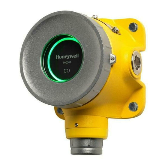
Page 7: Appearance
1.3 Accessories Part number Description SPXRLCAL Sensepoint XRL Calibration Cap SPXRLFLW Sensepoint XRL Flow Housing SPXRLDMK Sensepoint XRL Duct Mount Kit 2308B0923 Pole Mount Bracket Kit SPXCDWP Weather Protection SPXCDCC Collection Cone. Order together with SPXCDWP CAUTION All accessories are NOT part of explosion-proof certificate. -
Page 8: Detectable Gases
Introduction 1.4 Detectable Gases Sensepoint XRL is available for the detection of the following gases: • Oxygen (O • Toxic gases – Carbon monoxide (CO) – Hydrogen (H – Hydrogen sulfide (H • Combustible gases – Methane (CH For additional combustible gas availability, contact Honeywell Analytics. -
Page 9: Modbus Output Versions
Introduction Modbus Output Versions NOTE Use of the mobile app is required to change the configuration settings of the Modbus RTU interface. 1) +24 V DC or 24 V AC 2) 0 V or 24 V AC 3) A 4) B 1.6 Specifications Dimensions and Weight 159 mm... -
Page 10: Power Supply
Introduction Power Supply Sensepoint XRL requires an isolated power supply unit that is certified by a national or international standard, such as UL. Nominal DC input voltage 24 V DC Nominal AC input voltage 24 V AC, 50/60 Hz Inrush current... -
Page 11: Operating Environment
Introduction Digital Output Version In normal state During an alarm Electrochemical-cell-type sensors 0.5 W 1.0 W Catalytic-type sensors 1.6 W 2.0 W Infrared-type sensors 1.0 W 1.5 W Operating Environment Operating temperature −40 to 65 °C (−40 to 140 °F) Storage temperature 0 to 30 °C (32 to 86 °F) Humidity... -
Page 12: Installation
• When Sensepoint XRL reaches the end of its life, it should be disposed of in accordance with local regulations. • Do not use cleaning solvents or abrasives to clean the gas detector. - Page 13 Installation WARNING • Sensepoint XRL is designed for installation and use in Zone 1 or 2 hazardous areas in many countries including Europe and for Class 1 Division 1 or 2 area applications in North America. • Installation must be in accordance with the recognized standards of the appropriate authority in the country concerned.
- Page 14 Disposal should be according to local waste management requirements and environmental legislation. • Alternatively, old replaceable sensors may be securely packaged and returned to Honeywell Analytics clearly marked for environmental disposal. • Electrochemical sensors should NOT be incinerated as this action may cause the cell to emit toxic fumes.
-
Page 15: Installation Layout
Seek advice from experts where necessary. CAUTION Sensepoint XRL shall be installed on a flat surface or other suitable structure. For installation on a pole or pipe, use the official pole mount kit accessory. Sensepoint XRL sensor’s sinter must be pointing downward. - Page 16 The controller is supplying a nominal 24 V DC (V ), and the controller minimum allowable voltage of Sensepoint XRL is 11 V DC (V detector min Therefore the maximum allowable voltage drop across the cable between the controller and detector is V −...
-
Page 17: Main Electronics Module
Installation 2.4 Main Electronics Module 1) DOWN button 2) UP button 3) Inhibit level switch 4) Positive voltage output 5) Negative voltage output 6) Current sink/source selection switch 2.5 Wiring of mA Output Versions Power Connection When connecting to DC power, make sure that the polarity is correct. If AC power is used, ensure that terminal 4 “Common”... -
Page 18: Inhibit Level Selection
3 (4–20 mA) and terminal 2 (0 V) for source mode or terminal 1 (+24 V DC) for sink mode. Failure to do so will cause the Sensepoint XRL to enter a fault condition. - Page 19 Installation Detector Source Mode with DC Power VIN+ 24 VDC VE− VIN− 4–20mA 4–20mA 1) System controller 2) Sensepoint XRL detector 3) Current flow Detector Sink Mode with DC Power VIN+ 24 VDC VE− VIN− 4–20mA 4–20mA 1) System controller 2) Sensepoint XRL detector 3) Current flow...
- Page 20 Installation Detector Source Mode with AC Power VIN+ 24 VAC VE− VIN− 4–20mA 4–20mA 1) External power supply 2) Sensepoint XRL detector 3) System controller 4) Current flow Detector Sink Mode with AC Power VIN+ 24 VAC VE− VIN− 4–20mA 4–20mA...
-
Page 21: Wiring Of Modbus Output Versions
Installation 2.6 Wiring of Modbus Output Versions Modbus Connection For Modbus versions, up to 32 Sensepoint XRL detectors can be connected as shown in the diagram below. Refer to Appendix G for details on the Modbus registers. Cable Specification for Modbus Connection... -
Page 22: Securing The Detector To A Wall
Installation 2.7 Securing the Detector to a Wall The Sensepoint XRL transmitter has an integral mounting plate consisting of four mounting holes on the transmitter body. The transmitter may be fixed directly to a surface mounting, or to a horizontal or vertical pipe/structure, 40.0 to 70.0 mm (1.6 to 2.8 inches) in diameter/cross section. - Page 23 The allowable conductor size for the terminals is 0.2–2.5 mm (24–12 AWG). The Sensepoint XRL terminals will accept only wire sizes (solid- core or stranded) in this range. The temperature rating of the conductors should be greater than 80 °C. The terminals should be torqued between 0.5 N·m to 0.6 N·m.
-
Page 24: Ground Connections
Installation 5. Feed the cable through the cable gland. 6. Pull the terminal blocks to remove them from the connector module. 7. Connect cables to the terminal blocks, referring to the relevant wiring diagram. Strip and insert the end of each wire into the corresponding terminal hole. -
Page 25: Finalizing Installation
10.4 lb-in torque (1.17 N·m). 2.10 Finalizing Installation CAUTION When installing multiple Sensepoint XRL detectors at the same time, ensure that the electronics module is kept with its original housing. If misplaced in any other unit, the detector will not operate properly. - Page 26 Installation 1. Where used, tighten the sealing nut of the cable gland to secure the cable. 2. Refit the main electronics module to the connector module. 3. Replace the front cover by turning it clockwise ensuring that it is tight. 4.
-
Page 27: Commissioning
Chapter Commissioning NOTE The Sensepoint XRL gas detector is supplied from the factory pre-calibrated. However, it is strongly recommended that the detector response is checked and if necessary, re-calibrated before placing it into service. Refer to Calibration on page 33 for details on the correct calibration procedure. - Page 28 Commissioning Inhibited: The indicator is on steady yellow when the user has placed the detector into the inhibit state for maintenance or repair. Alarm: The indicator flashes red when the gas concentration is beyond the alarm-level threshold. Out-of-range alarm: The indicator rapidly flashes red when the gas concentration is beyond the full scale deflection of the detector.
-
Page 29: Maintenance
XRL. Never open any of the covers in the hazardous area without first isolating the power supply to the Sensepoint XRL. Correct field repair and replacement of parts on Sensepoint XRL is the responsibility of the user and must only be carried out by suitably qualified and trained personnel. -
Page 30: Maintenance Status Indicator
Maintenance DOWN OUTPUT VOLTAGE To inhibit the detector output: Press and hold the UP button for 2 seconds. To increase the output voltage: Briefly press the UP button. Pressing once increases by 0.02 V. To decrease the output voltage: Briefly press the DOWN button. Pressing once decreases by 0.02 V. -
Page 31: Calibration Cap
Maintenance status and second flash indicates span status . The indicator flashes long yellow followed by short green flash and short yellow flash when the zero calibration is successfully completed, but flashes long yellow followed by short red flash and short yellow flash if it fails. - Page 32 Maintenance A calibration cap accessory is available for the application of reference gas for the purpose of calibration. To fit the calibration cap, follow the steps below. 1. Push the calibration cap on the sensor cover as shown. 2. Connect a tube from a cylinder of calibration gas to either of the calibration cap’s gassing ports.
-
Page 33: Calibration
Maintenance 4. Refer to the regulator manufacturer for instructions on how to start and stop the gas flow from the cylinder. CAUTION Always use a gas cylinder that is within its expiration date. 4.4 Calibration NOTE It is preferential to use a smartphone running the app to perform maintenance tasks. - Page 34 Maintenance b) If there is any doubt of the quality of the atmosphere, connect a cylinder of fresh air to the detector using the installed tube or the calibration cap. For details about how to use a calibration cap, see Calibration Cap on page 31.
-
Page 35: Bump Test
Maintenance If repeated calibration attempts continue to fail, replace the gas sensor with a new one, and then try again. See Replacing the Sensor on page 4.5 Bump Test This section describes how to perform a bump test. For details about the mobile app, see Mobile App on page 39. -
Page 36: Replacing The Sensor
Sensepoint XRL. Attempting to use non-genuine sensors will void the warranty and could result in malfunction of the product. Correct field repair and replacement of parts on Sensepoint XRL is the responsibility of the user and must only be carried out by suitably qualified and trained personnel. - Page 37 Maintenance 4. Loosen the grub screw on top of the sensor cover. 5. Turn the sensor cover counterclockwise to remove it. 6. Pull out the gas sensor to remove it. 7. Ensuring that the sensor pins are correctly aligned, insert a new sensor into the sensor socket.
-
Page 38: Resetting Alarms And Faults
Maintenance 4.7 Resetting Alarms and Faults The default setting of each alarm is non-latching type. If you want to have a latching type alarm, change the alarm mode using the Sensepoint mobile app. 1. Pair with the target detector and tap Settings. 2. -
Page 39: Mobile App
Mobile App Use the Sensepoint App to allow your smart device to connect to Sensepoint XRL. This mobile app makes it much easier to configure and maintain Sensepoint XRL detectors. The general procedure of using the mobile app is as follows: 1. -
Page 40: Appendix
Appendix Detector Parameters... - Page 41 User Selectable User Selectable Cal Response Time Accuracy Detector Type Default Range Default Cal Point Resolution Range Gas Range t90 (s) ( ppm or % of applied gas which is the greater) Oxygen Fixed, 25.0% vol SPLIO1... 25.0% vol Fixed 20.9% vol <...
- Page 42 4–20 mA output. In terms of 4–20 mA, a 250 Ω load resistor was attached for the evaluation. If Sensepoint XRL’s flammable sensor is suspected to be damaged by aggressive substances, please perform bump test and calibration per this manual.
- Page 43 Detector Parameters Sensepoint XRL’s UL 2075 approval Sensepoint XRL was evaluated for UL 2075. The evaluation is valid only with: • CO • CH (Catalytic bead sensor) • 4–20 mA output with 250 Ω load resistor To guarantee Sensepoint XRL’s long-term compliance for UL 2075, at least twice a year (6 months interval) gas calibration is required.
-
Page 44: B Troubleshooting
Appendix Troubleshooting B.1 Warning Description Troubleshooting Warning 1 Calibration Overdue Calibrate the unit. Warning 3 BLE failure (BLE version only) Power-cycle the unit. If this warning occurs again, contact the manufacturer. Warning 4 Time/date not set (RTC not set) / RTC reset Set the time in the detector using the app. -
Page 45: Fault
Troubleshooting B.2 Fault Description Troubleshooting Fault 1 Internal communication failure Power-cycle the unit. If this fault occurs again, contact manufacturer. Fault 2 Cell failure Check the sensor connection. If this fault occurs again, replace sensor. Fault 3 Cell is producing a negative reading Calibrate the unit Fault 4 EEPROM is corrupted... -
Page 46: C Ordering Information
Sensepoint XRL Transmitter, cULus C1D1, Type 4X, O 25.0% v/v, Modbus, Yellow, ¾″ NPT SPLIC1BAXCNUZZ Sensepoint XRL Transmitter, cULus C1D1, Type 4X, CO, 4–20 mA, Charcoal, ¾″ NPT SPLIC1BAXYNUZZ Sensepoint XRL Transmitter, cULus C1D1, Type 4X, CO, 4–20 mA, Yellow, ¾″ NPT SPLIC1BMXCNUZZ Sensepoint XRL Transmitter, cULus C1D1, Type 4X, CO, Modbus, Charcoal, ¾″... -
Page 47: Accessories
Sensepoint XRL Transmitter, ATEX/IECEx Ex d, IP66, O 25.0% v/v, Modbus, Yellow, M20 SPLIC1BAXCMAZZ Sensepoint XRL Transmitter, ATEX/IECEx Ex d, IP66, CO, 4–20 mA, Charcoal, M20 SPLIC1BAXYMAZZ Sensepoint XRL Transmitter, ATEX/IECEx Ex d, IP66, CO, 4–20 mA, Yellow, M20 SPLIC1BMXCMAZZ... -
Page 48: Consumables
S (H) SPXRLMAG1 Sensepoint XRL Pluggable +Base Electronics Module, 4–20 mA, H SPXRLMAF1 Sensepoint XRL Pluggable +Base Electronics Module, 4–20 mA, Flammable CAT SPXRLMMO2 Sensepoint XRL Pluggable +Base Electronics Module, Modbus, O SPXRLMMC1 Sensepoint XRL Pluggable +Base Electronics Module, Modbus, CO... -
Page 49: D Warranty
Please contact your local Honeywell Analytics Service representative to register your claim. This is a summary. For full warranty terms please refer to the Honeywell Analytics’ General Statement of Limited Product Warranty, which is available on request. -
Page 50: E Safety Information For Wireless Devices
Appendix Safety Information for Wireless Devices E.1 FCC Compliance This device complies with part 15 of the FCC Rules. Operation is subject to the following two conditions: (1) This device may not cause harmful interference, and (2) this device must accept any interference received, including interference that may cause undesired operation. -
Page 51: Red Compliance
20 cm or more away from person’s body. E.2 RED Compliance Honeywell Analytics Asia Pacific Co., Ltd. hereby declares that this gas detector, Sensepoint XRL, is in compliance with the essential requirements and other relevant provisions of Directive 2014/53/EU. - Page 52 Safety Information for Wireless Devices interférences pouvant provoquer une utilisation non désirée de l’appareil. Cet équipement est conforme aux limites établies par FCC/ Industrie Canada en matière d’exposition aux radiations dans un environnement non contrôlé. Cet équipement ne doivent pas être colocalisés ou fonctionner en conjonction avec tout autre antenne ou émetteur.
-
Page 53: F Certification
Appendix Certification Electrical Safety • UL 61010-1 • CSA C22.2 No. 61010-1 • IEC/EN 61010-1 Electromagnetic Compatibility • EN 50270:2015 Radio • RED • FCC • BT SIG Enclosure Protection • IP66 • NEMA Type 4X Gas Performance • UL 2075 (CH and CO) •... - Page 54 Certification Explosion-Proof Specification • ATEX (DEMKO 17 ATEX 1872X) II 2 GD Ex db IIC T6 Gb Ex tb IIIC T85°C Db Tamb −40 to +65°C 1) Manufacturer information 2) Electrical rating 3) ATEX and IECEx protection marking 4) Chinese EPUP marking 5) Revision check box 6) QAN notified body number 7) WEEE marking...
- Page 55 Certification 1) Manufacturer information 2) US FCC and Canada IC approval 3) Serial number and part number 4) Electrical rating 5) WEEE marking 6) Canadian flammable gas performance approval 7) Revision check box 8) Country of origin 9) Hazloc marking for class/division and class/zone 10) cULus marking for hazloc approval 11) UL 2075 approval Specific Condition of Use for CAN/CSA-C22.2 No.60079-0 and...
- Page 56 Appendix Modbus Registers The Modbus version of Sensepoint XRL allows interaction with the gas detector using Modbus/RTU over an RS-485 physical layer. The Modbus interface provides a means to monitor and interrogate the detector with the addition of being able to reset alarms remotely. The...
- Page 57 Modbus Register Address Information Type Size Description Notes 30001 Main SW Version of Instrument 30002 EEP Version of Instrument 30004 to 3009 Location String string[12] Not used in Sensepoint XCL/XRL 30010 Modbus Slave ID 30011 Monitor Status 1 : Normal 2 : Warm Up after power on 3 : in Inhibit 12 : Calibration...
- Page 58 Modbus Register Address Information R/W Type Size Description Notes 40106 Alarm, Fault and Warning State This register contains 4 meaningful bits regarding the presence of alarms bit 0 Alarm 1 is active or faults. The bit assignments are as follows: Bit 0: AL1 bit 1 Alarm 2 is active active Bit 1: AL2 active Bit 4: Warning active Bit 6: Fault Active All others: bit 2,3 for future expansion...
- Page 59 Modbus Register Address Information Type Size Description Notes 40116 Reserved 40117 Temperature (Degrees C) Transmitter temperature 40118 to 40122 Reserved 40123 to 40131 Date and Time string[18] Format is “mm/dd/yy hh:mm:ss” 40132 Sensor Type 0x00 :ECC 0x01: FL CAT 0x02: IR 0x03: PID 0x04: MOS 40133 to 40136...
- Page 60 Modbus Register Address Information Type Size Description Notes 40163 Relay On Delay Time 40164 Relay Off Delay Time 40165 to 40166 User configured full scale range Display Range (Full Scale) 40167 to 40168 Alarm Threshold 1 40169 to 40170 Alarm Threshold 2 40171 to 40172 Target Calibration Gas Concentration 40173...
- Page 61 Keep this manual for later use. 3017M5023_1 HAA170035 © 2017 Honeywell Analytics...
- Page 62 Thank you for reading this data sheet. For pricing or for further information, please contact us at our UK Office, using the details below. UK Office Keison Products, P.O. Box 2124, Chelmsford, Essex, CM1 3UP, England. Tel: +44 (0)330 088 0560 Fax: +44 (0)1245 808399 Email: sales@keison.co.uk...