Table of Contents
Advertisement
Quick Links
Advertisement
Table of Contents

Related Manuals for GE DMS Go+


Summary of Contents for GE DMS Go+
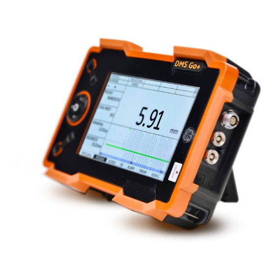
- Page 1 DMS Go+ Technical Reference and Operating Manual...
- Page 2 This edition 4 (05/2014) applies to the software version 3.20 (April 2, 2014) You will find the software version and the serial number of your instrument at CONFIG - ABOUT. © GE Sensing & Inspection Technologies GmbH | Technical content subject to change without notice.
-
Page 3: Function Groups And Functions
Function groups and functions DMS Go+ Edition 4 (05/2014) -
Page 4: Function Groups And Functions (Cont'd)
Function groups and functions (cont'd) Edition 4 (05/2014) DMS Go+... -
Page 5: Status Display Icons
Status display icons Power level indicators Icon Meaning Icon Meaning SD memory card is inserted, Battery charge level, flashes when the SD card is accessed remaining operating time in hours (approximate value) Display memory active (Function FREEZE), display is „frozen“. Charger/power adapter is connected, Measurement mode S-IP, DUAL percentage of battery charge level... -
Page 6: Basic Key Functions
Basic key functions Function key 1, functions are context-dependent Function key 2, functions are context-dependent; keys 1 and 2 simultaneously: Save screen shot Keypad, navigation between function groups and functions, changing settings Function key 3, functions are context-dependent Function key 4, function individually assignable (CONFIG – FUNC KEY), Edition 4 (05/2014) DMS Go+... -
Page 7: Navigation
Navigation Keys Function Navigation between function groups, adjusting values Navigation between functions within a function group Changing the display orientation (landscape - portrait) DMS Go+ Edition 4 (05/2014) - Page 8 Edition 4 (05/2014) DMS Go+...
-
Page 9: Table Of Contents
Contents Overview Effect of temperature variations ..1-6 Measurement of remaining wall thickness 1-6 Function groups and functions ..0-3 Choice of the probe....1-7 Function groups and functions (cont'd). - Page 10 Contents TopCOAT method 2.5 Recommended probe cables ..2-10 (measurement mode TOP-COAT) ..1-18 2.6 Recommended accessories..2-12 Auto-V (measurement mode AUTO-V) . . 1-19 B-scan.
- Page 11 Contents Principles of operation Operation 4.1 Overview of operator's controls ..4-2 5.1 Default settings ....5-2 Language setting .
- Page 12 Contents 5.3 Operating modes and views ..5-17 Setting the probe delay ....5-36 Changing the operating mode or view . . 5-17 5.9 Setting the gates .
- Page 13 Contents 5.13 Differential value display ... 5-46 File type CUSTOM GRID ... . . 6-6 Switching the differential value File type BOILER ....6-7 display on .
- Page 14 Contents 6.6 Editing files ..... . 6-24 Activating Auto-V....7-6 Expanding the file capacity .
- Page 15 Contents 8.4 Software updates ....8-4 File type CUSTOM GRID ... 10-13 Download of update files ... . . 8-4 File type CUSTOM POINT .
- Page 16 11 Specifications 11.1 Specifications of the DMS Go+ ..11-2 Display screen ....11-2 Display ......11-3 Connectors .
-
Page 17: Introduction
Introduction DMS Go+ Edition 4 (05/2014) -
Page 18: Safety Information
If you have any questions about the use of your test operated either with the corresponding lithium-ion bat- equipment, please contact your nearest representative teries or with the charger/power adapter. The charger/ of GE. power adapter meets the requirements of electrical safety class II. Edition 4 (05/2014) -
Page 19: Defects/Errors And Exceptional Stresses
Safety information 1 Introduction Defects/errors and exceptional stresses If you have reason to believe that a safe operation of your DMS Go+ is no longer possible, you have to dis- connect the instrument and secure it against uninten- tional reconnection. Remove the lithium-ion battery. A safe operation is no longer possible for example ●... -
Page 20: Important Information On Wall Thickness Measurement
1 Introduction Important information on wall thickness measurement 1.2 Important information on wall ● Training of the instrument operator (operator) thickness measurement ● Knowledge of special technical measurement re- quirements and limits ● Choice of the appropriate measuring device A T T E N T I O N The operation of an ultrasonic measuring device re- Please read the following information before quires proper training in ultrasonic thickness measure-... -
Page 21: Limits Of Ultrasonic Testing
NDT societies or at GE. object are covered by the sound beam. GE holds specialized training courses in the field of ul- Ultrasonic wall thickness measurement trasonic testing at regular intervals. The scheduled dates for these courses will be given to you on request. -
Page 22: Effect Of The Test Object Material
1 Introduction Important information on wall thickness measurement Effect of the test object material Effect of temperature variations If the material is not homogeneous, the sound waves The sound velocity within the test object also varies may propagate at different velocities in different parts of along with material's temperature. -
Page 23: Choice Of The Probe
Important information on wall thickness measurement 1 Introduction Choice of the probe In the case of curved coupling faces, for example on tubes, the dual-element probe used for the measure- The probe used for the measurement must be in good ment should be coupled in such a way that its acoustic condition, i.e. -
Page 24: Important Information On Wall Thickness Measurement Using The Dms Go
1 Introduction Important information on wall thickness measurement using the DMS Go+ 1.3 Important information on wall at temperatures below –10 °C. You should therefore carry out a 2-point calibration and repeat it in the case thickness measurement of major temperature jumps. using the DMS Go+ Couplant residues In order to ensure a correct probe zero offset, make sure... -
Page 25: Probes
Important information on wall thickness measurement using the DMS Go+ 1 Introduction Probes All probes equipped with a transmitter and a receiver el- ement require a V-path correction due to the inclined po- Please note that only probes specified in chapter 2 of sition of their transducer elements (with wall thickness- this manual are accepted for the DMS Go+. - Page 26 1 Introduction Important information on wall thickness measurement using the DMS Go+ The following probes have been corrected individually Zeroing before coupling the probe (OFF-BLOCK during the manufacturing process; the V-path correction zeroing) is stored in the probe. For some of these probes After powering the DMS Go+ on, the length of the delay (marked with *), this was additionally done for the oper- line below the transmitter element is determined at reg-...
- Page 27 Important information on wall thickness measurement using the DMS Go+ 1 Introduction Zeroing during probe coupling (ON-BLOCK zeroing) In the case of probes marked with *, the zero is deter- mined as an arithmetic mean of the two probe delay After coupling the probe (but before each individual wall lines.
-
Page 28: The Dms Go
1 Introduction The DMS Go+ 1.4 The DMS Go+ Special features of the DMS Go+ ● high measuring stability and reliability thanks to the zero crossing method Overview of functions ● automatic gain control for an improved reproducibility The DMS Go+ is a portable thickness gauge with an in- during corrosion tests tegrated data recorder You can use this instrument for ●... - Page 29 The DMS Go+ 1 Introduction ● high memory capacity with 2GB SD card. SD cards ● MicroGrid function for testing the direct surroundings with a memory capacity up to 16 GB can be used. of the measuring point ● measuring range 0.25 … 14000 mm (steel), depend- ●...
-
Page 30: Options
Options DMS Go+ Advanced ● TopCOAT technology for the simultaneous measure- Various options extend the basic functions of the DMS ment of coating thickness and metal thickness Go+ and can be enabled by a code in each case. ● Auto-V function for the wall thickness measurement of components with unknown sound velocity, without DMS Go+ Base calibration block during the measurement... -
Page 31: Wall Thickness Measurement
Wall thickness measurement using the DMS Go+ 1 Introduction 1.5 Wall thickness measurement using the DMS Go+ Principle of ultrasonic measurement At first, the DMS Go+ generates an electric initial pulse which is guided to the transmitter element of the probe. Once there, it is converted into a mechanical ultrasonic pulse. -
Page 32: Dual Mode (Measurement Mode Dual)
1 Introduction Wall thickness measurement using the DMS Go+ Dual mode (measurement mode DUAL) dual-element probe In the dual mode, the tasks of transmitting (T) and re- ceiving (R) are solved by two transducer elements ar- ranged in such a way that they are mechanically sepa- transmitter element receiver element rated from each other. -
Page 33: Single-Element Mode (Measurement Modes S-Ip, S-Peak, S-Flank)
Wall thickness measurement using the DMS Go+ 1 Introduction Single-element mode (measurement The rest of the energy of the first pulse transmitted pass- es further through the test material and returns as a modes S-IP, S-PEAK, S-FLANK) backwall echo. A single-element probe is used for transmitting and re- The time of flight between the two successive backwall ceiving the echoes in the single-element mode. -
Page 34: Topcoat Method (Measurement Mode Top-Coat)
1 Introduction Wall thickness measurement using the DMS Go+ TopCOAT method The following figure shows the operating principle of the TopCOAT method using a special probe. (measurement mode TOP-COAT) The patented TopCOAT method optimizes the corro- probe sion measurement through paint coatings. In this pro- cess, the test object and paint coating are measured at one go, and the two values are displayed on the screen. -
Page 35: Auto-V (Measurement Mode Auto-V)
Wall thickness measurement using the DMS Go+ 1 Introduction Auto-V (measurement mode AUTO-V) The function Auto-V is only available in the version DMS Go+ TC. The function Auto-V enables to measure the wall thick- ness of uncoated test objects without knowing the ma- probe terial's sound velocity. -
Page 36: B-Scan
1 Introduction Wall thickness measurement using the DMS Go+ B-scan The B-scan is a special, path-dependent representation of the test object's wall thickness. This representation is ideal for the display of corroded sections. The probe is guided over the section to be tested of the component for this representation. -
Page 37: Display Orientation
Wall thickness measurement using the DMS Go+ 1 Introduction Display orientation You can change the screen display of DMS Go+ from Display orientation in portrait mode landscape to portrait mode (see Section Display orien- tation, page 5-6). In addition, you can toggle between right-hand and left- hand operation (see Section Selecting the instrument orientation, page 5-6). -
Page 38: The Usm Go
1 Introduction The USM Go+ 1.6 The USM Go+ 1.7 How to use this manual The DMS Go+ uses the same operating principle as the This operating manual applies to all instrument versions portable flaw detector USM Go+. of the DMS Go+. Any differences in the functions or ad- justment values are marked in each case. -
Page 39: Overview
How to use this manual 1 Introduction Overview Chapter 6 Data Recorder This chapter describes the functions and options for us- The operation of the DMS Go+ is easy and quick to ing the data recorder, as well as the documentation of learn. -
Page 40: Layout And Presentation In
1 Introduction Layout and presentation in this manual 1.8 Layout and presentation in this Listings manual Listings are presented in the following form: ● Variant A To make it easier for you to use this manual, all operat- ing steps, listings, and special notes are always pre- ●... -
Page 41: Standard Package And Accessories
Standard package and accessories DMS Go+ Edition 4 (05/2014) -
Page 42: Standard Package
2 Standard package and accessories Standard package 2.1 Standard package Product code Description Order number Thickness gauge DMS Go+ TC-096 Transport case 109 709 LI-138 Lithium-ion battery, 7.4 V, 3.9 Ah, rechargeable 109 707 LiBC-139 AC power adapter/charger, 100V … 260V AC 109 708 SD memory card 8 GB Display screen protector foils (10 pieces) -
Page 43: Add-On Functions
Add-on functions 2 Standard package and accessories 2.2 Add-on functions Product code Description Order number TopCOAT and Auto-V Extended Data Recorder DMS Go+ Edition 4 (05/2014) -
Page 44: Preconfigured Function Packages
2 Standard package and accessories Preconfigured function packages 2.3 Preconfigured function packages Product code Description Order number Base Thickness gauge DMS Go+ or DMS Go+ Base with TopCOAT and Auto-V Base with Extended Data Recorder Advanced Base with TopCOAT, Auto-V, and Extended Data Recorder Edition 4 (05/2014) DMS Go+... -
Page 45: Recommended Probes
Recommended probes 2 Standard package and accessories 2.4 Recommended probes Product code Description Order number Probes for corrosion measurements (one-sided zeroing during coupling): DA 301 5 MHz, measuring range 1.2 … approx. 200 mm 56 904 DA 303 2 MHz, measuring range 5 … approx. 300 mm 56 905 DA 0.8 G 800 kHz, measuring range 7 …... - Page 46 2 Standard package and accessories Recommended probes Product code Description Order number Dialog probes for corrosion measurements (one-sided zeroing before coupling): DA 401 5 MHz, measuring range 1.2 … approx. 200 mm 58 637 DA 403 2 MHz, measuring range 5 … approx. 300 mm 58 639 DA 408 800 kHz, measuring range 7 …...
- Page 47 Recommended probes 2 Standard package and accessories Product code Description Order number Probes for high-temperature measurements DA 315 2 MHz, measuring range 5 … 150 mm, up to +200 °C 57 167 DA 317 5 MHz, measuring range 2 … 80 mm, up to +200 °C 57 168 DA 319 10 MHz, measuring range 1 …...
- Page 48 2 Standard package and accessories Recommended probes Product code Description Order number Probes for special test tasks: DA 312 B16 10 MHz, measuring range 0.6 … approx. 12 mm, dia. 3 mm 66 934 KBA 525 10 MHz, measuring range 0.6 … approx. 20 mm, dia. 5 mm 113-516-002 FH2ED-REM Dialog probe, 8 MHz,...
- Page 49 Recommended probes 2 Standard package and accessories Product code Description Order number Probes for precision measurements in single-element mode (DMS Go+ and DMS Go+ TC): CLF 4 Delay probe, 15 MHz, measuring range 0.25 … approx. 25 mm 113-527-665 CLF 5 Contact probe, 10 MHz, measuring range 1 …...
-
Page 50: Recommended Probe Cables
2 Standard package and accessories Recommended probe cables 2.5 Recommended probe cables Product code Description Order number DA 231 1.5 m (for DA 401, DA 403, DA 408) 53 616 DA 233 1.5 m (for DA 315, DA 317, DA 319, DA 411) 54 999 DA 235 1.5 m (for DA 305, DA 412) - Page 51 Recommended probe cables 2 Standard package and accessories Product code Description Order number MPKLL 2 2 m (for CA 214, G5KB, G2N) 58 791 MPKL 2 2 m (for K1SC) 50 486 DMS Go+ Edition 4 (05/2014) 2-11...
-
Page 52: Recommended Accessories
2 Standard package and accessories Recommended accessories 2.6 Recommended accessories Product code Description Order number Hihg-temperature coupling paste, 200 … 600 °C, 100g tube 56 567 LI-138 Lithium-ion battery, 7.4 V, 3.9 Ah, rechargeable 109 707 LiBC-139 AC power adapter/charger, 100 V … 260 V AC 109 708 CA-040 Battery adapter for external charging of battery... - Page 53 Recommended accessories 2 Standard package and accessories Product code Description Order number UL MATE L Basic data transfer program UltraMATE L 022-104-560 UL MATE Evaluation and documentation program UltraMATE 022-103-660 DMS Go+ Edition 4 (05/2014) 2-13...
- Page 54 2 Standard package and accessories Recommended accessories 2-14 Edition 4 (05/2014) DMS Go+...
-
Page 55: Initial Start-Up
Initial start-up DMS Go+ Edition 4 (05/2014) -
Page 56: Instrument Positioning
3 Initial start-up Instrument positioning 3.1 Instrument positioning 3.2 Power supply Fold out the prop-up stand on the rear side of the The DMS Go+ can be operated either with an external DMS Go+ and position the instrument on a flat base so charger/power adapter or with the corresponding lithi- that you can easily read the display. - Page 57 Power supply 3 Initial start-up Connecting the instrument Connect the DMS Go+ to the mains socket-outlet by means of the corresponding charger/power adapter. The socket-contact for connecting the charger/power adapter is located on the side of the DMS Go+. – Align the Lemo plug of the charger/power adapter with the red mark on the socket (1).
-
Page 58: Operation Using Batteries
3 Initial start-up Power supply Operation using batteries You should only use the corresponding lithium-ion bat- tery for the battery operation. Inserting batteries The battery compartment is located on the rear of the in- strument. The cover is fastened with two attachment screws. - Page 59 Power supply 3 Initial start-up – Place the battery in the battery compartment so that the marking faces upwards and the contacts are pushed against the connector pins (1). – Insert the cover of the battery compartment with the side opposite to the screws at first, and push the lugs (3) into the housing recesses.
- Page 60 3 Initial start-up Power supply Checking the charge level of the lithium-ion battery The lithium-ion battery is provided with a battery charge level indicator. Five light-emitting diodes (1) indicate the level of battery charge. Check the battery charge level before inserting it into the instrument. The number of diodes that are lit up has the following meaning: ●...
- Page 61 Power supply 3 Initial start-up Power level indicator The DMS Go+ is automatically powered off if the opera- tion is no longer ensured. All settings are retained during The DMS Go+ is equipped with a power level indicator battery exchange and are immediately available again that allows to estimate the remaining operating time of afterwards.
-
Page 62: Charging The Batteries
3 Initial start-up Power supply Charging the batteries Charging status The LED on the charger/power adapter indicates the You can charge the lithium-ion batteries either directly status of charging. within the instrument or in an external charger. off: Charger/power adapter is not con- nected to the power supply Internal charging yellow steady light: Charger/power adapter is not con-... -
Page 63: Connecting A Probe
Connecting a probe 3 Initial start-up 3.3 Connecting a probe Single-type connectors A T T E N T I O N You can connect all probes recommended in chapter 2 of this manual. In addition to the probe, you need a suit- If a probe is connected incorrectly, the con- able probe cable for the connection between the probe sequence would be a mismatching which... -
Page 64: Inserting The Sd Memory Card
3 Initial start-up Inserting the SD memory card 3.4 Inserting the SD memory card You can use any standard SD memory card in the DMS Go+. To insert and to remove the memory card, you have to open the watertight cover at the top of the instru- ment. -
Page 65: Starting The Dms Go
Starting the DMS Go+ 3 Initial start-up 3.5 Starting the DMS Go+ Powering On To start the DMS Go+, shortly press the Power key (1) on the side of the instrument casing. The software is initialized. During this, the display will re- main blank for about 3 seconds. -
Page 66: Powering Off
3 Initial start-up Starting the DMS Go+ Powering Off The instrument starts with the factory default settings (for language selection, see Section Language setting, To power the DMS Go+ off, shortly press the Power key page 5-2). on the side of the instrument casing. The settings of all function values and the default set- tings (language and units) are retained after powering off. -
Page 67: Principles Of Operation
Principles of operation DMS Go+ Edition 4 (05/2014) -
Page 68: Overview Of Operator's Controls
4 Principles of operation Overview of operator's controls 4.1 Overview of operator's controls Function key 1, functions are context-dependent Function key 4, function is individually assignable (CONFIG – FUNC KEY), Function key 2, functions are context-dependent; keys 1 and 2 simultaneously: Save screen shot Display for representation of readings, A-scan, B-scan, functions, and data Keypad, navigation between function groups and... -
Page 69: Display Screen
Display screen 4 Principles of operation 4.2 Display screen N o t e For toggling between the different display Display modes modes and operating modes, see Section Operating modes and views, page 5-17. The DMS Go+ has a high-resolution display screen for the representation of the A-scan or the B-scan, for the display of readings, important setup parameters and Display mode reading and B-scan... - Page 70 4 Principles of operation Display screen Display mode Data Recorder Landscape and Portrait mode If a data recorder file is loaded, you will see the name You can change the screen display of DMS Go+ from and the structure of the data recorder file above the cur- landscape to portrait mode.
-
Page 71: Functions On The Display Screen
Display screen 4 Principles of operation Functions on the display screen Icons and information Function groups Keypad functions The names of the seven function groups are shown at You can see the current functions of the four function the bottom of the display screen. The currently selected keys in the top left corner of the display screen. -
Page 72: Display Of Reading
4 Principles of operation Display screen Status display icons Display of reading The status displays in the top left corner of the display The current reading is always displayed in enlarged screen, above the functions, inform about certain active mode above the A-scan or B-scan. functions, operating modes, or operating status (see If an alarm threshold is exceeded, the displayed reading Section Status display icons, page 0-5). -
Page 73: Navigation And Function Keys
Navigation and function keys 4 Principles of operation 4.3 Navigation and function keys Function keys Apart from the keypad, two groups of keys, including Keypad two function keys each, are arranged next to the display screen (see Section Overview of operator's controls, The five keys of the keypad next to the display screen page 4-2). -
Page 74: Key Combinations
4 Principles of operation Navigation and function keys Key combinations You can carry out some functions by means of key com- binations. To achieve this, you have to press several function keys at the same time (see Section Overview of operator's controls, page 4-2). Function Keys Screen shot... -
Page 75: Operational Concept
Operational concept 4 Principles of operation 4.4 Operational concept View Data Recorder If a data recorder file has been loaded, additional infor- mation about the file is automatically displayed above Changing the display views the reading together with the file structure including the saved readings. -
Page 76: Selecting And Setting Functions
4 Principles of operation Operational concept Selecting and setting functions – Press the left or right arrow keys in order to choose a function group. Shown below the A-scan are the seven function groups – Press the down arrow key in order to select the first which you can directly select using the keys of the key- function of the function group chosen previously. - Page 77 Operational concept 4 Principles of operation During the coarse adjustment, the name of the function is Disabled functions displayed in capital letters (DISPLAY RANGE), whereas If the option INSPECTOR is chosen in the function it is displayed in lower-case letters during the fine adjust- MENU MODE, the functions are suppressed and cannot ment (display range).
- Page 78 4-12 Edition 4 (05/2014) DMS Go+...
-
Page 79: Operation
Operation DMS Go+ Edition 4 (05/2014) -
Page 80: Default Settings
5 Operation Default settings 5.1 Default settings The following languages are available: ● Bulgarian ● Chinese ● German Language setting ● English ● Finnish ● French ● Italian ● Japanese ● Dutch ● Norwegian ● Polish ● Portuguese ● Romanian ●... -
Page 81: Units Setting
Default settings 5 Operation Units setting Resolution setting You can use the function UNIT (function group CON- You can use the function RESOLUTION (function group FIG) to select the required units (mm or in). You can CONFIG) to select the resolution for the display of read- change the units any time. -
Page 82: Radix
5 Operation Default settings Radix Last reading You can choose the radix symbol. All data are displayed You can choose the display mode for the thickness val- and saved using the selected radix. ue measured last – after uncoupling and before cou- pling the next time. -
Page 83: Date Format, Date, And Time
Default settings 5 Operation Date format, Date, and Time – In the function group CONFIG, select the function DT FMT. – Choose the required date format. The time format is changed together with the date format. – Select the function DATE TIME. –... -
Page 84: Selecting The Instrument Orientation
5 Operation Default settings Selecting the instrument orientation Display orientation You can change the screen display of DMS Go+ from landscape to portrait mode. It is not possible to access the settings and parameters in the portrait mode. – Briefly press the center key of the keypad in order to rotate the screen display by 90 degrees. -
Page 85: Assignment Of Function Key 4
Default settings 5 Operation Assignment of function key 4 The following settings are possible: ● NOT DEFINED (no function assigned) ● NOTE (choosing a comment, see page 6-20) ● µGRID (adding a MicroGrid, see page 6-29) ● LH/RH (instrument orientation, see page 5-6) ●... -
Page 86: Function Lockout
5 Operation Default settings Function lockout Disabling all setup functions – In the function group CONFIG, select the function MENU MODE. – Choose the option INSPECTOR in order to disable the access to all setup functions. – Choose the option EXPERT in order to enable the ac- cess to all setup functions. - Page 87 Default settings 5 Operation Enabling individual setup functions – Press the center key of the keypad in order to exclude the selected function from the general lockout. The – In the function group CONFIG, select the function function is marked with a cross. LOCKOUT.
-
Page 88: Password Protection
5 Operation Default settings Password protection You can save a password only if there is no password protection yet or if the EXPERT mode is active (see You can protect the access to the setup functions with a Section Function lockout, page 5-8). password. - Page 89 Default settings 5 Operation Changing a password Deactivating password protection You can change the password at any time. To do this, To deactivate the password protection, proceed in the you must first enter the current password. same way as for changing the password. Instead of a new password, however, you don't choose any charac- –...
-
Page 90: Power Saving Mode
5 Operation Default settings Power saving mode You have a choice between the following automatic power down times: ● 1 min ● 2 min ● 3 min ● 4 min ● 5 min ● 10 min ● 15 min ● 30 min To save power during longer stops or breaks, you can –... -
Page 91: Configuring Data Boxes
Default settings 5 Operation Configuring data boxes You have a choice between the following data: ● OFF (no display) ● P-DLY (probe delay) ● LOC (measuring location) ● M-GAIN (maximum gain setting) ● TEMP (material temperature setting) ● GAIN (current gain) ●... - Page 92 5 Operation Default settings – In the function group MEASURE, select the function – Finally, press the function key 1 (function EXIT) in or- RESULTS. der to exit the selection menu and to save the selec- tion. The selected data are then displayed in the data –...
-
Page 93: Default Settings Of The Display
Default settings of the display 5 Operation 5.2 Default settings of the display You can set the brightness of the display and select a value from 1 to 10 for this purpose. The DMS Go+ is equipped with a high-resolution color N o t e display. -
Page 94: Selecting The Color Scheme
5 Operation Default settings of the display Selecting the color scheme N o t e All color schemes are suitable for indoor use. For outdoor use, we recommend SCHEME 3 and SCHEME 4. – In the function group CONFIG, select the function COLOR. -
Page 95: Operating Modes And Views
Operating modes and views 5 Operation 5.3 Operating modes and views Changing the operating mode or view – In the function group MEASURE, select the function You can choose from different operating modes and dis- MODE. play views for different tasks. –... -
Page 96: Saving The Settings
5 Operation Saving the settings 5.4 Saving the settings N o t e The file name can consist of a maximum of 20 characters. – In the function group PARAM, select the function SAVE P-SET. – Press one of the left or right arrow keys. –... -
Page 97: Loading Settings
Saving the settings 5 Operation Loading settings Deleting settings You can load and use instrument settings saved to the You can delete instrument settings saved to the SD SD memory card. memory card. N o t e N o t e You can only load files with the file extension You can only delete files with the file exten- DGO in the directory DMSGO\DATASETS. -
Page 98: Preparing For Measurements
5 Operation Preparing for measurements 5.5 Preparing for measurements To prepare for measurements, you have to: ● Select a suitable probe. You can use the DMS Go+ to measure wall thicknesses ● Select the suitable measurement mode. or distances and to assess residual wall thicknesses in a simple way. -
Page 99: Choosing The Probe Type
Preparing for measurements 5 Operation Choosing the probe type N o t e After connecting a suitable probe for the task, you have When a dialog probe (probe designation to choose the probe type to adjust the DMS Go+ to the DA4... -
Page 100: Choosing The Measurement Mode
5 Operation Preparing for measurements Choosing the measurement mode S-PEAK The measurement mode S-PEAK is available for single- You have to choose the suitable measurement mode for element probes. the task. By doing so, you define the method for operat- ing the instrument or the data used for determining the The wall thickness is determined on the basis of the ul- measurement result. - Page 101 Preparing for measurements 5 Operation DUAL N o t e The measurement mode DUAL is available for dual-el- Only the measurement modes supported by ement probes. the selected probe type are displayed as op- The wall thickness is determined on the basis of the ul- tions to choose from.
-
Page 102: Carrying Out The Calibration
5 Operation Carrying out the calibration 5.6 Carrying out the calibration A T T E N T I O N The same probe and the same measure- Calibrations ment mode have to be chosen for the calibra- tion as for the subsequent measurement You have to carry out various calibrations on the basis operation. -
Page 103: Probe Zero Offset
Carrying out the calibration 5 Operation Probe zero offset MANUAL This method uses the reference block at the instrument You can choose between automatic and manual probe rear with known wall thickness and sound velocity in or- zero offset. der to determine the zero offset for the connected probe. N o t e The method is applicable to both single-element probes and dual-element probes and it even works in critical... - Page 104 5 Operation Carrying out the calibration MANUAL zeroing – Keep the probe coupled as long as the message Ac- quiring, please stay coupled is visible on the dis- – Clean the coupling face of the probe from any dirt and play screen.
-
Page 105: Calibration To Zero And To Sound Velocity
The reference block at the instrument rear is only used for carrying out the zeroing pro- cess. Only use the calibration blocks recommend- ed by GE for further calibrations (please refer to chapter 2). DMS Go+ Edition 4 (05/2014) 5-27... - Page 106 5 Operation Carrying out the calibration 1-point calibration – Apply some couplant to the instrument reference block and couple the probe. The zeroing is started. The 1-point calibration is carried out using the reference After finishing it, the message Probe zero complete. block at the instrument rear and a calibration block with Remove probe from zero block.
- Page 107 Carrying out the calibration 5 Operation – When the message Remove probe from Cal Std. is – Press one of the left or right arrow keys in order to displayed on the screen, you can uncouple the probe. start the calibration. The message Couple to Low The 1-point calibration is finished, the instrument is Cal Std.
- Page 108 5 Operation Carrying out the calibration – If the wall thickness displayed on the screen is not identical with the high-calibration thickness calibra- tion block, press the function key 2 (function ENTER). – Select the digits that you wish to change using the left and right arrow keys, and change the value using the up and down arrow keys.
-
Page 109: Setting The Sound Velocity
Carrying out the calibration 5 Operation Setting the sound velocity – In the function group PROBE&CAL, select the func- tion VELOCITY. If the sound velocity in the test object is known, you can – Press the function keys 3 and 4 in order to select a also set it directly without applying one of the calibration material with the corresponding sound velocity. -
Page 110: Carrying Out Measurements
5 Operation Carrying out measurements 5.7 Carrying out measurements If the coupling was successful, the digits in the display of readings are shown in solid mode. N o t e – Watch the A-scan and the display of readings, and Please observe the application notes in wait until both of them are stable. -
Page 111: A-Scan Configuration
A-scan configuration 5 Operation 5.8 A-scan configuration Display delay Make your choice of displaying the set display range You can adjust the A-scan display on the screen to your starting from the surface of the test object or in a section requirements. -
Page 112: Setting The Gain
5 Operation A-scan configuration Setting the gain The switch between the value for HIGH and the value for LOW is at a material velocity of 6248.4 m/s = 246000 You can use the gain to adjust the sensitivity necessary in/s to differentiate between steel and aluminum. for making the backwall echoes visible on the display screen at the required height. -
Page 113: Selecting The Display Update Rate
A-scan configuration 5 Operation MANUAL Selecting the display update rate The automatic gain control is switched on. The maxi- You can select the interval for measurements and the A- mum gain setting is fixed and corresponds to the value scan update, as well as for the display of readings. selected in the function MAX GAIN. -
Page 114: Selecting The Rectification Mode
5 Operation A-scan configuration Selecting the rectification mode Setting the probe delay You can select the rectification mode of echo pulses ac- Every probe is equipped with a delay line between the cording to your application. transducer and the coupling face. The sound pulse must first pass through this delay line before it can enter the You have a choice between the following rectification test object. -
Page 115: Setting The Gates
Setting the gates 5 Operation 5.9 Setting the gates N o t e The functions of the gates are only effective Task of the gates within the display range. The gate B is only visible and adjustable if one of the measure- The gates are used for selecting the measuring point for ment modes DUAL-MULTI, S-FLANK, or the digital time-of-flight or amplitude measurement to... -
Page 116: Gate Width
5 Operation Setting the gates Gate width Gate threshold You can set the width of gate A and gate B. You can set the vertical position of the gate in percent- age of screen height (A-scan). N o t e –... -
Page 117: Configuring Alarm Functions
Configuring alarm functions 5 Operation 5.10 Configuring alarm functions Minimum value alarm The alarm is triggered if the set minimum value is fallen The DMS Go+ can trigger an alarm signal if preset read- below. ings are exceeded or fallen below. –... -
Page 118: Min/Max Mode
5 Operation MIN/MAX mode 5.11 MIN/MAX mode The minimum and the maximum value of the current se- quence are displayed in small digits above the last read- ing obtained. The DMS Go+ enables you to determine the minimum and the maximum thickness reading of a series or se- The expiring waiting time is displayed at the top right quence of measurements. -
Page 119: Switching The Min/Max Mode On
MIN/MAX mode 5 Operation Switching the MIN/MAX mode on Clearing a sequence of measurements You can switch the MIN/MAX mode on any time. The You can clear all readings of the current sequence of first sequence of measurements starts automatically at measurements. -
Page 120: Thickness Profiles With The B-Scan
5 Operation Thickness profiles with the B-scan 5.12 Thickness profiles with the B-scan Apart from the A-scan, the DMS Go+ presents another possibility of graphical evaluation: the B-scan. The B-scan enables you to display a thickness profile of the test object on the screen of the DMS Go+. You can carry out measurements continuously over a maximum period of 30 seconds for the B-scan display with the values from these measurements being used... -
Page 121: Switching The B-Scan Display On
Thickness profiles with the B-scan 5 Operation Switching the B-scan display on Setting the display time You can switch the B-scan display on any time. The display time (in seconds) defines the period of time during which the thickness profile should be recorded. The display of the thickness profile starts automatically At the end of this time (maximum 30 seconds), the in- at the first successful coupling after switching the B-... -
Page 122: Setting The Waiting Time
5 Operation Thickness profiles with the B-scan Setting the waiting time Minimum value line You can set a waiting time (in seconds) for interruptions. You can display a minimum reading as a line in the The waiting time starts as soon as the probe is uncou- B-scan. -
Page 123: Recording A B-Scan
Thickness profiles with the B-scan 5 Operation Recording a B-scan – To save, press the function key 2 (function SEND). – Press the function key 3 (function CLEAR) in order to After setting the display time and the waiting time, you clear the B-scan and to start a new recording. -
Page 124: Differential Value Display
5 Operation Differential value display 5.13 Differential value display Switching the differential value display on You can switch the differential value display on any The differential value display shows the difference be- time. tween a nominal value setting and the measured thick- ness value. -
Page 125: A-Scan View
A-scan view 5 Operation 5.14 A-scan view If necessary, you can display the A-scan so that it cov- ers the complete display screen height. The current thickness reading is then no longer shown in enlarged mode above the A-scan but in reduced from at the top right corner of the display screen. -
Page 126: Other Functions
5 Operation Other functions 5.15 Other functions Saving calibration block data You can save the data of the calibration blocks for the probe zero offset and the calibration to the sound veloc- ity to the instrument. N o t e The data in the function VEL REF. - Page 127 Other functions 5 Operation Calibration block data for the sound velocity – Set the other parameters in the same way. – In the function group MEASURE, select the function – Finally, press the function key 2 (function DONE) in VEL REF. BLOCK. order to save the data.
-
Page 128: Calibration Reminder
5 Operation Other functions Calibration reminder If you switch on the reminder functions of DMS Go+, a reminder icon is displayed at the top left corner of the display screen once the selected criterion is reached (see Section Status display icons, page 0-5). –... -
Page 129: Temperature Compensation
Other functions 5 Operation Temperature compensation If the calibration block cannot be heated, the DMS Go+ can use the temperature compensation in order to recal- culate the wall thickness of the test object and to display it correctly. If the temperature of a test object increases, the sound velocity of the material increases slightly as well. -
Page 130: Display Freeze (Freeze)
5 Operation Other functions – In the function group PROBE&CAL, select the func- Display freeze (FREEZE) tion TEMP COMP. You can freeze the display screen of the DMS Go+. The – Press one of the left or right arrow keys in order to A-scan and the displayed thickness value are then fro- choose the option ENABLE. -
Page 131: Gate Magnifier (Zoom)
Other functions 5 Operation Gate magnifier (ZOOM) The function ZOOM expands the gate A up to a maxi- mum covering the entire display width. This enables you to examine the signal in gate A in more detail. You can only switch on the zoom function if a signal is positioned in the gate. -
Page 132: Enabling Options (Upgrade)
5 Operation Enabling options (Upgrade) 5.16 Enabling options (Upgrade) N o t e To order options, you need the serial number of your instrument (please see function ABOUT in the function group CONFIG). – In the function group CONFIG, select the function CODE. -
Page 133: Data Recorder
Data Recorder DMS Go+ Edition 4 (05/2014) -
Page 134: Overview Of Functions
6 Data Recorder Overview of functions 6.1 Overview of functions You can use the Data Recorder e.g. to ● save measurement results to the DMS Go+ The Data Recorder of DMS Go+ is a flexible and power- ● save graphical measurement data (A-scan, B-scan) ful tool for the organization of measurement tasks and the management of measured values. - Page 135 Overview of functions 6 Data Recorder File name Flags The file name is meant for the clear identification of the Flags are automatically added to a reading if additional file and it must always be entered. information is stored, for example the A-scan, or a min- imum value or maximum value alarm.
-
Page 136: File Types
6 Data Recorder File types 6.2 File types File type LINEAR The measurement results are organized in linear mode. To save measurement results, you can choose a file In this mode, the measurement locations are consecu- type organized according to your application. The tively numbered with exactly one measuring point being DMS Go+ offers six different file type options for you to assigned to each measurement location. -
Page 137: File Type Custom Linear
File types 6 Data Recorder File type CUSTOM LINEAR File type CUSTOM POINT This file type has two structural elements (measurement This file type has two structural elements (measurement location and measuring point) Measurement locations location and measuring point) Measurement locations must be identified by specific names, measuring points and measuring points must be identified by specific are consecutively numbered. -
Page 138: File Type Grid
6 Data Recorder File types File type GRID File type CUSTOM GRID This file type is especially suitable for testing areas in This file type is suitable for applications in which each which the measurement locations are arranged on a measurement location consists of a grid of the same grid. -
Page 139: File Type Boiler
File types 6 Data Recorder File type BOILER The measurement results are organized in a structure with 3 elements (Elevation, Tube, Point). In this type, ev- ery elevation is identified by a specific name. The num- ber of measuring points is determined during file cre- ation. -
Page 140: Master Comment List
6 Data Recorder Master comment list 6.3 Master comment list Creating a master comment list – In the function group DR, select the function MAS- You can save a comment to each measurement result. TER CMT. You can choose the corresponding comment from a comment list. -
Page 141: Changing Master Comments
Master comment list 6 Data Recorder – Enter the comments for the other list items in the Changing master comments same way. You can change the comments of master comments at – Finally, press the function key 1 (function EXIT). The any time. - Page 142 6 Data Recorder Master comment list – Press the function key 2 (function BKSP) in order to delete the last character. – Press the function key 4 (function CONFIRM). The comment is saved. – Change the comments for the other list items in the same way.
-
Page 143: Working With Files
Working with files 6 Data Recorder 6.4 Working with files Creating a new file N o t e You can create Data Recorder files in order to load them for subsequent measurement tasks and to save mea- If you wish to create a file by copying an al- surement results to them in a structured mode. - Page 144 6 Data Recorder Working with files – Press one of the up or down arrow keys in order to – Select the individual parameters and set the required mark the basic parameters available in the selected values. file type. – If the selected file type allows it, press the function –...
-
Page 145: Deleting Files
Working with files 6 Data Recorder Deleting files If you don't want to use a file any longer, you can delete it at any time. A T T E N T I O N You cannot undo the deletion of files! –... -
Page 146: Saving Measurement Results
6 Data Recorder Saving measurement results 6.5 Saving measurement results Loading a file Before starting the measurements, you have to select After creating a Data Recorder file, you can carry out the required file for saving the measurement results measurements and save the measurement results to first. -
Page 147: Saving Readings
Saving measurement results 6 Data Recorder Saving readings – Carry out a measurement as usual (see Section Car- rying out measurements, page 5-32). After selecting a file, the empty data points for saving – Press the function key 3 (function SEND). The read- the readings are displayed above the A-scan. -
Page 148: Special Measuring Point Functions
6 Data Recorder Saving measurement results Special measuring point functions Selecting individual measuring points Special functions are available for editing individual If necessary, you can mark a certain data point (measur- measuring points. ing point) in order to save a reading specifically to this data point. -
Page 149: Clearing A Reading
Saving measurement results 6 Data Recorder Clearing a reading Overwriting readings You can clear a stored reading at any time. By selecting a data point which already has a reading assigned to it, you cannot normally overwrite the read- – In the function group DR, select one of the functions ing saved there. -
Page 150: Saving Readings With A-Scans
6 Data Recorder Saving measurement results Saving readings with A-scans – Load a Data Recorder file (see Section Loading a file, page 6-14). You can save readings with or without an A-scan. To do – In the function group DR, select the function PROP- this, you have to configure the send function according- ERTIES. - Page 151 Saving measurement results 6 Data Recorder If the reading was saved with an A-scan, a small triangle is shown in the top right corner of the corresponding data point. DMS Go+ Edition 4 (05/2014) 6-19...
-
Page 152: Adding Comments
6 Data Recorder Saving measurement results Adding comments – Select a measuring point which has a reading saved to it (see Section Selecting individual measuring If necessary, you can add one or several comments to points, page 6-16). each reading. To do this, choose the required com- –... - Page 153 Saving measurement results 6 Data Recorder – Finally, press the function key 1 (function EXIT) in or- You cannot add any comments to empty data points (no der to end the selection of comments. reading saved). If the marking has automatically ad- vanced to the next, empty data point after saving the The code letters of the selected comments are displayed reading, you have to select the data point with the cor-...
-
Page 154: Editing A File Comment List
6 Data Recorder Saving measurement results Editing a file comment list – Load a Data Recorder file (see Section Loading a file, page 6-14). If necessary, you can change and complete the com- – In the function group DR, select the function PROP- ments of a file comment list which have been automati- ERTIES. - Page 155 Saving measurement results 6 Data Recorder – Choose other characters in the same way. – Press the function key 2 (function BKSP) in order to delete the last character. – Press the function key 4 (function CONFIRM). The comment is saved. –...
-
Page 156: Editing Files
6 Data Recorder Editing files 6.6 Editing files Expanding the file capacity If necessary, you can expand a file for saving additional You can edit stored files at any time in order to adjust measurement results. Depending on the file type, you the requirements to the corresponding measurement can then add optional measuring points, elevations, col- task and to e.g. - Page 157 Editing files 6 Data Recorder – Press the left or right arrow key in order to select the – Press the function key 4 (function INSERT). A form group EDIT. window appears. – Press either the up or down arrow key in order to se- –...
-
Page 158: Deleting Parts Of A File
6 Data Recorder Editing files As an alternative to inserting between items already ex- Deleting parts of a file isting, you can append additional items to the end of the You can remove empty items which are no longer need- file. -
Page 159: Editing Header Data
Editing files 6 Data Recorder Editing header data – Load a Data Recorder file (see Section Loading a file, page 6-14). If necessary, you can change some information normal- – In the function group DR, select the function PROP- ly stored in the file header when creating a new file. The ERTIES. - Page 160 6 Data Recorder Editing files – Press either the up or down arrow key in order to se- lect the required parameter. – Press the left or right arrow key in order to mark the first character. – Press the center key of the keypad to select the marked character.
-
Page 161: Adding A Microgrid
Editing files 6 Data Recorder Adding a Microgrid Microgrids can have the following sizes: ● 2 × 2 (= 4 measuring points) If you wish to record additional measurement values, ly- ing in the immediate vicinity of the measuring point, to a ●... - Page 162 – Press the function key 1 (function µGRID). A selec- The grid of the Microgrid is then displayed above the A- tion menu is displayed. scan instead of the usual file structure. You can then en- ter data in the data points of the Microgrid by saving readings.
- Page 163 Editing files 6 Data Recorder – Carry out the measurements as usual (see Section You cannot add any Microgrids to empty data points (no Carrying out measurements, page 5-32). reading saved). If the marking has automatically ad- vanced to the next, empty data point after saving the –...
- Page 164 6 Data Recorder Editing files Reloading a Microgrid You can reload a previously created Microgrid at any time in order to save other readings to it. You have to se- lect the data point containing the corresponding reading first (see Section Selecting individual measuring points, page 6-16).
-
Page 165: Automatic Advance
Editing files 6 Data Recorder Automatic advance By configuring this function, you can adjust the order for saving measurement results to the corresponding test After saving a reading using the function SEND, the next task. In this way, you can e.g. determine whether you data point is usually selected automatically in order to wish to proceed by rows or by columns for saving mea- save the following reading to that position. - Page 166 6 Data Recorder Editing files Depending on the file type, you can define the following AUTO REVERSE parameters: You can choose whether to start from the beginning again after saving the last reading in a category or ADVANCE TIME whether to edit the grid by meandering (for example, the first column from the top to the bottom, the second col- Time after saving a reading at the end of which the next umn from the bottom to the top, the third column from...
- Page 167 Editing files 6 Data Recorder AUTO REVERSE – Load a Data Recorder file (see Section Loading a file, page 6-14). In this case, the parameter refers to the second category. – In the function group DR, select the function PROP- ERTIES.
-
Page 168: Evaluations
6 Data Recorder Evaluations 6.7 Evaluations The following data are available: ● Number of readings saved Viewing statistical evaluations ● Number of measuring points without a reading ● Number of obstructed measuring points (OBSTR.) Taking the stored data as a basis, the DMS Go+ makes different statistical evaluations available for each file ●... - Page 169 Evaluations 6 Data Recorder – Load a Data Recorder file (see Section Loading a Searching for certain data file, page 6-14). You can search the statistics for certain data. Only the – In the function group DR, select the function PROP- data of one or several statistical parameters are then ERTIES.
-
Page 170: Changing The View (Spread - List)
6 Data Recorder Evaluations Changing the view (Spread – List) You can toggle between the list display mode and the spread display mode for readings at any time. The list mode presents the advantage of directly show- ing additional information about each reading: ●... -
Page 171: Viewing Stored Reading Attachments
Evaluations 6 Data Recorder Viewing stored reading attachments – Press either the up or down arrow key in order to se- lect the parameter ATTACHMENT TYPE. You can view the attachments, A-scan, B-scan, or Mi- crogrid stored for a reading at any time on the display screen. -
Page 172: Documenting Measurements
6 Data Recorder Documenting measurements 6.8 Documenting measurements – Load a Data Recorder file (see Section Loading a file, page 6-14). – In the function group DR, select the function EX- Data export PORT. You can export the measured values recorded and the –... -
Page 173: Screen Shots
Documenting measurements 6 Data Recorder Screen shots – Press the function keys 1 and 2 at the same time. The screen shot is saved. The memory card icon flashes You can save screen shots (images of the current during saving (see Section Status display icons, screen display content) independently of the Data Re- page 0-5). - Page 174 6 Data Recorder Documenting measurements 6-42 Edition 4 (05/2014) DMS Go+...
-
Page 175: Special Functions Of The Dms Go+ Tc
Special functions of the DMS Go+ TC DMS Go+ Edition 4 (05/2014) -
Page 176: Basics
7 Special functions of the DMS Go+ TC Basics 7.1 Basics N o t e The DMS Go+ TC has two special functions that enable Only the echoes of the second pair of trans- improved methods of measurement in connection with a ducer elements are visible in the A-scan. - Page 177 Basics 7 Special functions of the DMS Go+ TC This means that e.g. the sound path between the trans- At the same time, the sound velocity determined in this mitter and receiver element of the first pair of elements way can be used for the exact measurement of wall is known, composed of the delay line (S ) and the thickness.
- Page 178 7 Special functions of the DMS Go+ TC Basics This method enables to always determine the wall thick- ness on the basis of the first backwall echo. This makes the TopCOAT method suitable e.g. for the residual wall Probe thickness measurement on heavily fissured backwalls when measurements between two backwall echoes (DUAL-MULTI) are no longer possible.
- Page 179 Basics 7 Special functions of the DMS Go+ TC A T T E N T I O N An absolute prerequisite for both functions or measurement methods is the calibration of the DMS Go+ with the probe to be used. The calibration enables to determine the sound path of the first pair of transducer ele- ments, forming the basis for all subsequent...
-
Page 180: Measurement Mode Auto-V
To be able to use the Auto-V function, you have to con- Applications nect a special 4-element probe to the DMS Go+. The following probes from GE are suitable for Auto-V: The Auto-V function is used for the simultaneous deter- mination of sound velocity and wall thickness on non- ●... -
Page 181: Zeroing For Auto-V
Measurement mode Auto-V 7 Special functions of the DMS Go+ TC Zeroing for Auto-V Carrying out probe zero offset A T T E N T I O N A T T E N T I O N It is absolutely necessary that you use low- The calibration described below is an abso- viscosity couplant for the probe zero offset lute prerequisite for the subsequent mea-... - Page 182 7 Special functions of the DMS Go+ TC Measurement mode Auto-V – Apply some couplant to the reference block at the in- strument rear and to the reference block made of copper. – In the function group PROBE&CAL, select the func- tion PROBE ZERO.
-
Page 183: Measurement Mode Topcoat
To be able to use the TopCOAT function, you have to Applications connect a special 4-element probe to the DMS Go+. The following probes from GE are suitable for the Top- The TopCOAT method is used for the determination of COAT method: wall thickness and coating thickness on coated test ob- jects. -
Page 184: Zeroing For Topcoat
7 Special functions of the DMS Go+ TC Measurement mode TopCOAT Zeroing for TopCOAT Carrying out probe zero offset A T T E N T I O N A T T E N T I O N It is absolutely necessary that you use low- The calibration described below is an abso- viscosity couplant for the probe zero offset lute prerequisite for the subsequent mea-... -
Page 185: Sound Velocity In The Test Object
Measurement mode TopCOAT 7 Special functions of the DMS Go+ TC – Apply some couplant to the reference block at the in- Sound velocity in the test object. strument rear and to the reference block made of The sound velocity in the test object must be known and copper. -
Page 186: Calibration To The Sound Velocity
7 Special functions of the DMS Go+ TC Measurement mode TopCOAT Calibration to the sound velocity – Apply some couplant to all three calibration blocks. – In the function group PROBE&CAL, select the func- For calibrating the DMS Go+ TC, you need three cali- tion CALIBRATION. -
Page 187: Sound Velocity In The Coating
Measurement mode TopCOAT 7 Special functions of the DMS Go+ TC – Select the digits that you wish to change using the Sound velocity in the coating left and right arrow keys, and change the value using In addition to the sound velocity in the material, the the up and down arrow keys. - Page 188 7 Special functions of the DMS Go+ TC Measurement mode TopCOAT Storing the coating velocity – Press one of the left or right arrow keys in order to set the value. You have to store the exact sound velocity in the coating in the DMS Go+ TC for accurate measurements.
-
Page 189: Maintenance And Care
Maintenance and care DMS Go+ Edition 4 (05/2014) -
Page 190: Instrument Care
8 Maintenance and care Instrument care 8.1 Instrument care 8.2 Battery care Clean the instrument and its accessories using a moist Battery care cloth. The following are exclusively recommended for cleaning: The capacity and life of batteries mainly depend on the correct handling. -
Page 191: Charging The Batteries
Any repair work may only be carried out by The handling of batteries, the charging process, and the members of authorized GE service staff. meaning of LEDs and power indicators is described in detail in Chapter Operation using batteries, page 3-4. -
Page 192: Software Updates
You can download the latest software version for your You can install the latest software updates for the DMS instrument from the GE Inspection Technologies web- Go+ yourself. You can check the version installed in site by means of any customary web browser. -
Page 193: Installing An Update
Software updates 8 Maintenance and care – In the column Title, click the entry USM Go/DMS Go Installing an update Software Update. N o t e – Read the displayed text Software Terms and Con- ditions Acceptance and click I ACCEPT to confirm. Only one file with the extension .sdu may be The Registration Form appears. - Page 194 8 Maintenance and care Software updates – Press the function key 2 (1), the function key 4 (2), and the Power key (3) at the same time, and hold all three keys pressed until the display screen is turned on and the message FLASH UPGRADE MODE ap- pears.
-
Page 195: Interfaces And Peripherals
Interfaces and Peripherals DMS Go+ Edition 4 (05/2014) -
Page 196: Interfaces
9 Interfaces and Peripherals Interfaces 9.1 Interfaces Overview The interfaces are located under the watertight cover on the top of the instrument. – Push the lock of the hinged cover (1) in the direction of the arrow in order to open the cover. –... -
Page 197: Usb Interface
The service interface is only meant to be used for ser- and is used for data exchange with a PC. vice purposes by the GE customer service. When you connect the instrument to a PC via a standard USB cable, the SD memory card inserted into the instru- ment is added to the list of active drives on the PC. -
Page 198: Peripherals
9 Interfaces and Peripherals Peripherals 9.2 Peripherals The DMS Go+ is not provided for the direct connection of peripherals, e.g. printers or monitors. For more details on documentation, see Section Docu- menting measurements, page 6-40. Edition 4 (05/2014) DMS Go+... -
Page 199: Appendix
Appendix DMS Go+ Edition 4 (05/2014) 10-1... -
Page 200: Application Notes
10 Appendix Application notes 10.1 Application notes Surface quality Tool marks running parallel to the coupling face may cause measurement errors in the case of a great peak- General notes to-valley height. If the acoustic separation layer of the probe is set at right angles to the marks, this effect does The DMS Go+ is easy to use and produces reliable and not occur. - Page 201 Application notes 10 Appendix Wall thickness measurement on hot test objects Equipped with the probe DA 305 for high-temperature applications, the DMS Go+ can be used for wall thick- Probe ness measurements on materials with a surface tem- perature of max. 600 °C. A coupling paste especially developed for such applications is likewise required.
-
Page 202: Sound Velocities
10 Appendix Sound velocities 10.2 Sound velocities To avoid any damages to the probe contact face, do not turn or rotate the probe while it is in contact with the test surface. If the surface is curved, pay attention to the cor- The table shows typical sound velocities in different ma- rect orientation of the acoustic separation layer of the terials (longitudinal wave). - Page 203 Sound velocities 10 Appendix Material Material Gold 3240 Platinum 3960 Rubber (hard) 220 … 2540 Plexiglas (PMMA) 2730 Material Polyamide (6.6 Nylon) 2600 Rubber (soft) 1460 … 2200 Polyethylene (PE hard) 2530 Cast iron (lamellar) 3800 … 4700 Polyethylene (PE soft) 2000 Cast iron (vemicular) 4700 …...
- Page 204 10 Appendix Sound velocities Material Steel (duplex) 5750 … 5950 Steel (ferritic) 5920 Cast steel (austenitic) 5730 Teflon (PTFE) 1340 … 1400 Titanium 6100 … 6230 Uranium 3200 … 3380 Uranium dioxide 4520 … 5160 Uranium carbide 4010 … 4640 Tungsten 5200 …...
-
Page 205: Data Recorder File Types
Data Recorder file types 10 Appendix 10.3 Data Recorder file types N o t e In the file format STANDARD, only the wall thickness is recorded. In the file format EXTENDED, the recording includes extend- ed data (e.g. date and time of recording, probe type, sound velocity, measurement mode). - Page 206 10 Appendix Data Recorder file types CALIBRATION Free text, up to 16 characters UNITS Units: mm or in COMPANY Free text, up to 16 characters DESCRIPTION Free text, 4 lines with up to 16 characters each INSPECTOR Free text, up to 16 characters TEMP Free text, up to 16 characters T-MIN...
-
Page 207: File Type Grid
Data Recorder file types 10 Appendix File type GRID READING TYPE File format: STANDARD or EXTENDED GRID LABELING Alphabetic or numeric labeling of rows and columns: COL-A/ROW-# (columns alphabetically, rows numerically), COL-#/ROW-A (columns numerically, rows alphabetically) STARTING ROW Number of the first row (1 … 702) ENDING ROW Number of the last row (1 …... - Page 208 10 Appendix Data Recorder file types COMPANY Free text, up to 16 characters DESCRIPTION Free text, 4 lines with up to 16 characters each INSPECTOR Free text, up to 16 characters TEMP Free text, up to 16 characters T-MIN Minimum value which triggers an alarm if fallen below T-MAX Maximum value which triggers an alarm if exceeded MEMO...
-
Page 209: File Type Custom Linear
Data Recorder file types 10 Appendix File type CUSTOM LINEAR READING TYPE File format: STANDARD or EXTENDED NUMBER OF LOCATIONS Number of measurement locations (1 … 999) LOC. LABEL LENGTH Maximum number of characters for labeling measurement locations (1 … 16) START POINT First measuring point (1 …... - Page 210 10 Appendix Data Recorder file types T-MIN Minimum value which triggers an alarm if fallen below T-MAX Maximum value which triggers an alarm if exceeded MEMO Free text, up to 16 characters PREFIX TEXT Text before the automatic numbering STARTING NUMERIC Start value for the automatic numbering INCREMENT BY Increment value for the automatic numbering...
-
Page 211: File Type Custom Grid
Data Recorder file types 10 Appendix File type CUSTOM GRID READING TYPE File format: STANDARD or EXTENDED NUMBER OF LOCATIONS Number of measurement locations (1 … 999) LOC. LABEL LENGTH Maximum number of characters for labeling measurement locations (1 … 16) GRID LABELING Alphabetic or numeric labeling of rows and columns: COL-A/ROW-# (columns alphabetically, rows numerically),... - Page 212 10 Appendix Data Recorder file types COMPANY Free text, up to 16 characters DESCRIPTION Free text, 4 lines with up to 16 characters each INSPECTOR Free text, up to 16 characters TEMP Free text, up to 16 characters T-MIN Minimum value which triggers an alarm if fallen below T-MAX Maximum value which triggers an alarm if exceeded MEMO...
-
Page 213: File Type Custom Point
Data Recorder file types 10 Appendix File type CUSTOM POINT READING TYPE File format: STANDARD or EXTENDED NUMBER OF LOCATIONS Number of measurement locations (1 … 999) LOC. LABEL LENGTH Maximum number of characters for labeling measurement locations (1 … 16) POINTS PER LOC. - Page 214 T-MIN Minimum value which triggers an alarm if fallen below T-MAX Maximum value which triggers an alarm if exceeded MEMO Free text, up to 16 characters PREFIX TEXT Text before the automatic numbering STARTING NUMERIC Start value for the automatic numbering INCREMENT BY Increment value for the automatic numbering SUFFIX TEXT...
-
Page 215: File Type Boiler
Data Recorder file types 10 Appendix File type BOILER READING TYPE File format: STANDARD or EXTENDED NUMBER OF ELEVATIONS Number of elevations (1 … 999) ELEV. LABEL LENGTH Maximum number of characters for labeling elevations (1 … 16) STARTING TUBE # First measuring point of the first tube (1 …... - Page 216 10 Appendix Data Recorder file types TEMP Free text, up to 16 characters T-MIN Minimum value which triggers an alarm if fallen below T-MAX Maximum value which triggers an alarm if exceeded MEMO Free text, up to 16 characters PREFIX TEXT Text before the automatic numbering of measurement location STARTING NUMERIC Start value for the automatic numbering of measurement location...
-
Page 217: Flag Symbols
Flag symbols 10 Appendix 10.4 Flag symbols The flag symbols are displayed on the screen in addition to the readings in the column FLAGS if the spread view- ing format is selected. > maximum value alarm triggered < minimum value alarm triggered an A-scan is stored for the reading a B-scan is stored for the reading a Micro Grid has been created for the reading... -
Page 218: Function Directory
10 Appendix Function directory 10.5 Function directory N o t e Some functions are only available if the cor- responding options are enabled by entering the license code. Function Function group Description see page POWER DOWN CONFIG Power saving function, powers down the instrument after a preset 5-12 time if no operation takes place. - Page 219 Function directory 10 Appendix Function Function group Description see page VIEW Display of the readings in spread or list format. 6-38 DATE TIME CONFIG Setting of date and time. DATE FORMAT CONFIG Choice of date format. RADIX CONFIG Choice of the character for decimal notation. Period or comma. THK CAL PROBE&CAL Choice of the method for the calibration to sound velocity.
- Page 220 10 Appendix Function directory Function Function group Description see page VEL REF. BLOCK CONFIG Calibration block data for the operating modes TopCOAT and 5-48 AUTO-V. CALIBRATION PROBE&CAL Start of calibration to the sound velocity. 5-27 Master Cmt Editing the master comment list. LOAD P-SET PARAM Loading of instrument settings from a file on the memory card.
- Page 221 Function directory 10 Appendix Function Function group Description see page ORIENTATION CONFIG Configuration of the instrument for left-handed or right-handed operation. PASSWORD CONFIG Setting of a password for the protection of setup functions. 5-10 PROBE ZERO PROBE&CAL Start of probe zero offset. 5-25 PROBE DELAY PROBE&CAL...
-
Page 222: Eu Declaration Of Conformity
Should you nevertheless detect an error on your instru- ment, power the instrument off and remove the batter- ies. Inform your local GE customer service and support, indicating the error and describing it. 10-24 Edition 4 (05/2014) - Page 223 If there is anything special that you would like to know Lewistown, PA 17044 about the use, handling, operation, and specifications of the instruments, please contact your nearest GE repre- T +1 717 242 03 27 sentative or turn directly to: F +1 717 242 26 06 GE Sensing &...
-
Page 224: Environmental Protection
Electronic Equipment) If you need more information on the collection, reuse, and recycling of recyclable material, please contact your GE is an active participant in Europe's Waste Electrical local waste management company. and Electronic Equipment (WEEE) take-back initiative, directive 2002/96/EC. -
Page 225: Disposal Of Batteries
Environmental protection regulations 10 Appendix Disposal of batteries What do the markings mean? Batteries and accumulators must be marked (either on This product contains batteries that cannot be disposed the battery, on the accumulator, or on their packaging, of as unsorted municipal waste in the European Union. depending on the size) with the separate collection sym- Please read carefully the data sheets for the battery bol. - Page 226 10 Appendix Environmental protection regulations The risks and your role in minimizing them ● Lead is poisonous in all compounds. It accumulates in the body so that any form of exposure is critical. In- By participating in the proper waste disposal, you would gestion and inhalation of lead can cause severe inter- make a valuable contribution towards reducing the dam- nal injuries.
-
Page 227: Recycling Directives
Recycling directives 10 Appendix 10.9 Recycling directives Overview DMS Go+ Edition 4 (05/2014) 10-29... - Page 228 10 Appendix Recycling directives 10-30 Edition 4 (05/2014) DMS Go+...
- Page 229 Recycling directives 10 Appendix Item No. Recycling/Material Code Description Lithium-ion battery Lithium-ion battery in the battery compartment on the rear panel of instrument Battery ML1200 Lithium backup battery on the main board Polycarbonate, Polymex, TPE, brass, Upper and lower instrument covers, as well as battery lid, partly copper contain steel, upper instrument cover contains embedded brass threads, keypad...
-
Page 230: Materials To Be Disposed Of Separately
10 Appendix Recycling directives Materials to be disposed of separately 10-32 Edition 4 (05/2014) DMS Go+... - Page 231 Recycling directives 10 Appendix DMS Go+ Edition 4 (05/2014) 10-33...
- Page 232 10 Appendix Recycling directives Item No. Recycling/Material Code Description Lithium-ion battery Battery compartment, remove after opening the battery lid Battery ML1200 On the main board To remove the battery, loosen the screws on the rear panel of the instrument. After this, the lower instrument cover can be taken off.
-
Page 233: Other Materials And Components
Recycling directives 10 Appendix Other materials and components DMS Go+ Edition 4 (05/2014) 10-35... - Page 234 10 Appendix Recycling directives 10-36 Edition 4 (05/2014) DMS Go+...
- Page 235 Recycling directives 10 Appendix DMS Go+ Edition 4 (05/2014) 10-37...
- Page 236 10 Appendix Recycling directives 10-38 Edition 4 (05/2014) DMS Go+...
- Page 237 Recycling directives 10 Appendix DMS Go+ Edition 4 (05/2014) 10-39...
- Page 238 10 Appendix Recycling directives 10-40 Edition 4 (05/2014) DMS Go+...
- Page 239 Recycling directives 10 Appendix Item No. Recycling/Material Code Description Main board, battery board, flexible PC PC boards mounted in the housing board TFT display Mounted in the upper instrument cover under a stainless steel lid which is wrapped up in yellow foil Parts of the housing, polycarbonate, Parts of the housing, keypad Polymex, keypad...
-
Page 240: Recycling Data Of The Dms Go
10 Appendix Recycling directives Recycling data of the DMS Go+ Recycling/Material Code Weight approx. (g)Description Material/components to be disposed of and handled separately Lithium-ion battery Battery compartment Battery ML1200 Battery holder on the main board Material/components possibly interfering with certain recycling processes PC boards PC boards within the housing Parts of the housing, polycarbonate,... - Page 241 Recycling directives 10 Appendix Recycling/Material Code Weight approx. (g)Description Normally advantageous material/components Stainless steel Cover of TFT display Steel Protecting cover on the main board Magnesium die casting Upper watertight instrument cover, prop-up stand Rubber Rubber sleeves on the LEMO connectors, rubber joints Fasteners, cables, clamps, screws and bolts, ...
- Page 242 10 Appendix Recycling directives 10-44 Edition 4 (05/2014) DMS Go+...
-
Page 243: Specifications
Specifications DMS Go+ Edition 4 (05/2014) 11-1... -
Page 244: Specifications Of The Dms Go
11 Specifications Specifications of the DMS Go+ 11.1 Specifications of the DMS Go+ Display screen Active range (W × H) 108.0 × 64.8 mm, diagonal 5 inches Size 5 inches Resolution (W × H) 800 × 480 pixels Contrast ratio ≥300 Brightness ≥200 cd/m²... -
Page 245: Display
Specifications of the DMS Go+ 11 Specifications Display Display shift (display delay) 0 … 3,500 µs Probe delay 0 … 1,000 µs Velocity 250 … 16,000 m/s Resolution of readings 0.01 mm or 0.1 mm (0.001 inches or 0.01 inches), selectable over the entire measuring range Display modes Temperature-corrected thickness... -
Page 246: Connectors
11 Specifications Specifications of the DMS Go+ Connectors Probe connectors 2 × LEMO-00, mechanical reverse polarity protection USB interface Micro USB connector Service interface 1 × Mini-RS232C, only used for service purposes Pulser Pulser mode Square-wave pulser Pulser voltage automatically matched to the probe (120 V or 250 V) Pulser falling/rising time max. -
Page 247: Receiver
Specifications of the DMS Go+ 11 Specifications Receiver Digital gain 110 dB dynamic range, automatic gain control with manual (set by user) High, Low, and Auto gain limit Memory Card slot SD card slot for standard SD cards Capacity 8 GB, SD card Datasets 100,000 measurements per file. -
Page 248: Environment
11 Specifications Specifications of the DMS Go+ Environment Battery Operating time: 6 hours with full charge Charging method (standard): internal with charger/power adapter Charging method (optional): external charger Charge level: proportional charge level indicator Charger/power adapter Universal power supply unit 100 … 240 VAC, 50/60 Hz, meets the requirements of CCC, CE, UL, CSA, and PSE Size (W ×... -
Page 249: Protection
Specifications of the DMS Go+ 11 Specifications Protection Damp heat and humidity (storage) 10 cycles: 10 hrs at +60 … +30 °C, 10 hrs at +30 … +60 °C, transition within 2 hrs (507.4) Temperature shock (storage) 3 cycles: 4 hrs at -20 … +60 °C, 4 hrs at +60 °C transition within 5 minutes (503.4, Procedure II) Vibration: General exposure: 1 hr per axis,... -
Page 250: Options
11 Specifications Specifications of the DMS Go+ Storage temperature range –20 … +60 °C, 24 hrs including battery Compliance EMC/EMI: EN 55011, EN 61000-6-2:2001 Ultrasound: EN 12668, ASTM E1324, E317, ANSI/NCSL Z 540-1-1994, MIL STD 45662A, MIL STD 2154 Options TopCOAT TopCOAT technology for the simultaneous measurement of coating thickness and metal thickness... -
Page 251: Specifications According To
Specifications according to EN 12668 11 Specifications 11.2 Specifications according to EN 12668 You will find the specifications according to EN 12668 for your instrument on the product CD included in the standard package. DMS Go+ Edition 4 (05/2014) 11-9... - Page 252 11-10 Edition 4 (05/2014) DMS Go+...
- Page 253 Index DMS Go+ Edition 4 (05/2014) 12-1...
- Page 254 12 Index Numerics Alarm signal 5-39 APPEND 6-26 1-PT 5-28 Application notes 10-2 1ST ADVANCE BY 6-34 A-SCAN 5-17, 5-47 1ST ADVANCE DIR 6-34 A-scan 4-3, 4-9 2ND ADVANCE BY 6-34 Viewing 6-39 2ND ADVANCE DIR 6-34 A-scan view 5-47 2-PT 5-29 ATTACHMENT TYPE 6-39 AUTO 5-25...
- Page 255 12 Index Care 8-2 CAL TEMP 5-51 Charge level 0-5, 3-7 CALIBRATION 5-28, 5-29, 7-12 Charging 8-3 Calibration 5-24 Checking 3-6 Calibration block Indicator 3-7 Saving data 5-48 Warning of low charge level 3-7 Calibration reminder 5-50 Battery charge level 0-5, 3-7 Care 8-2 Battery icon 3-7 Charge level of battery 3-6...
- Page 256 12 Index COMMENTS 6-21, 6-38 DATE TIME 5-5 Components 10-36 Default settings 5-2 Color scheme 5-16 CONFIRM 5-9, 5-18 Date and Time 5-5 Connecting Display 5-15 Charger/power adapter 3-3 Instrument 3-12 Probe 3-9 Language 5-2 CUR TEMP 5-51 Resolution 5-3 CUSTOM GRID 6-6, 10-13 Units 5-3 CUSTOM LINEAR 6-5, 10-11...
- Page 257 12 Index DISPLAY DELAY 5-33 ENTER 5-19 Display delay 5-33 Environmental compatibility 10-27 Display freeze 5-52 Environmental protection regulations 10-27 Display orientation 0-7, 1-21, 5-6 Evaluations 6-36 Display orientation in landscape mode 1-21 EXIT 5-14 Display orientation in portrait mode 1-21 EXPERT 5-10 DISPLAY RANGE 5-33 EXPLORER 6-11, 6-13, 6-14...
- Page 258 12 Index File types 10-7 Firmware 8-4 Gain 5-34 Flag symbols 10-19 Gate A Start 5-37 FLAGS 6-38, 10-19 GATE A THR. 5-38 FREEZE 0-5, 5-32, 5-52 Gate A Width 5-38 Freeze 0-5 Gate B Start 5-37 FUNC KEY 5-7 GATE B THR.
- Page 259 12 Index List 6-38 LOAD P-SET 5-19 Icons 4-5 Loading Instrument orientation 5-6 Settings 5-19 Instrument settings 5-18 Lock 4-11 Interfaces 9-2 LOCKOUT 5-9 Key combinations 4-8 Maintenance 8-3 Key lock 4-11 MANUAL 5-25 Keypad 4-7 Master Cmt 6-8, 6-9 Keypad functions 0-6, 4-5 Material Instrument 10-27...
- Page 260 12 Index Measuring accuracy 10-2 NOTE 6-16, 6-20 Memory card Inserting 3-10 Removing 3-10 OBSTR 6-15, 6-16 MENU MODE 5-8 Operating manual 1-22 Microgrid 6-29 Operating mode MIN 5-39, 5-44 Changing 5-17 Min Alarm 5-39, 5-44 Operating time 0-5 MIN/MAX 5-17, 5-41 Operational concept 4-9 Clearing a sequence of measurements 5-41 Operator's controls 4-2...
- Page 261 12 Index Connecting 3-9 PROBE DELAY 5-36 PARAM 5-18, 5-19 Probe delay 5-36 PASSWORD 5-10, 5-11 PROBE DELAY (probe delay) 5-36 Password 5-10 PROBE ZERO 5-26, 7-8, 7-11 Changing 5-11 Probe zero offset 5-24 Lost 5-10 Saving 5-10 PROPERTIES 6-18, 6-22, 6-24, 6-26, 6-27, 6-35, 6-37, 6-39 Password protection Deactivating 5-11...
- Page 262 12 Index Repair 8-3 SD memory card 0-5 Reset 3-12, 4-8 SEND 6-15, 6-16, 6-18, 6-31, 6-33 RESOLUTION 5-3 SEND FUNCTION 6-18 Resolution setting 5-3 SEND MIN 5-41 Restart 3-12 Sensitivity 5-34 Restoring 3-12 Serial number 3-11 RESULTS 5-13, 5-14 Service addresses 10-25 Service interface 9-3 Setting units 5-3...
- Page 263 12 Index Specifications 11-2 Thickness profile 5-42 Specifications according to EN12668 11-9 THK CAL 5-28, 5-29 Spread 6-38 TIME 5-43 Start display 3-11, 5-54 Time 5-5 Starting 3-11 TIMEOUT 5-44 Starting point of gate 5-37 Toggling Function group 4-10, 4-11 Statistics 6-36 TOP-COAT 1-18 STATS 6-37...
- Page 264 12 Index Upgrade 5-54 ZERO BLOCK 5-48 USB interface 9-2, 9-3 Zeroing MANUAL 5-26 USER 5-25, 5-26 USER 5-26 ZOOM 5-53 µGRID 6-16, 6-30, 6-32 VEL REF. BLOCK 5-49, 7-14 VELOCITY 5-31 Version number 8-4 VIEW 6-38 View 5-17 Changing 5-17 Waste disposal 8-6, 10-28 WEEE directive 10-27 Width of gate 5-38...