
Related Manuals for GE TVRMS2 Series


Summary of Contents for GE TVRMS2 Series
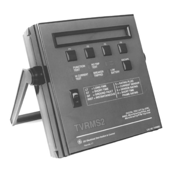
- Page 1 GEK–97367C TVRMS2 Digital Test Kit User’s Guide GE TVRMS2 Specs Provided by www.AAATesters.com...
- Page 2 ® MicroVersaTrip Digital Test Kit Controls, Indicators, and Connections...
- Page 3 Features may be described herein that are not present in all hardware and software systems. GE Electrical Distribution & Control assumes no obligation of notice to holders of this document with respect to changes subsequently made.
-
Page 4: Table Of Contents
TVRMS2 Digital Test Kit Table of Contents Chapter 1. Introduction 1–1 Description .............................1 1–2 Application to Pre-RMS-9 Trip Units.....................1 1–3 Definition of Terms ..........................2 1–4 Test Selection ............................2 Chapter 2. Controls, Indicators, and Connections 2–1 Front Panel.............................3 2–2 Top Panel (Test Cable Connection.......................3 2–3 Bottom Panel............................4 Chapter 3. - Page 5 TVRMS2 Digital Test Kit Table of Contents Overcurrent Simulation Test ......................18 5–5 High Current Primary Injection ......................19 Trip Unit Ground Fault Defeat .....................19 Trip Unit Pickup and Trip Monitor .....................20 5–6 Trip Unit Quick Test..........................20...
- Page 6 TVRMS2 Digital Test Kit List of Figures and Tables Figures 1. TVRMS2 Digital Test Kit connected to a MicroVersaTrip PM™ Trip Unit..........1 2. Front panel of the Test Kit........................3 3. Bottom panel of the Test Kit, showing the 120 Vac power cord and the battery-storage area....4 4.
-
Page 7: Chapter 1. Introduction
TVRMS2 Digital Test Kit Chapter 1. Introduction 1–1 Description 1–2 Application to Pre-RMS-9 Trip Units The TVRMS2 Digital Test Kit is a light-weight, portable The TVRMS2 Test Kit cannot be used to test earlier test instrument designed for field testing of RMS-9, Epic, MicroVersaTrip solid-state programmers. -
Page 8: Definition Of Terms
TVRMS2 Digital Test Kit Chapter 1. Introduction 1–3 Definition of Terms 1–4 Test Selection The terms listed and defined in Table 2 are displayed on The Test Kit can perform three types of tests on Trip the Test Kit and are used throughout this guide. Units: •... -
Page 9: Chapter 2. Controls, Indicators, And Connections
TVRMS2 Digital Test Kit Chapter 2. Controls, Indicators, and Connections 2–1 Front Panel under low-battery conditions can yield erroneous test results. Figure 2 shows the front panel of the Test Kit. • Escape Key – Pressing the key returns the Test ESCAPE Kit to its power-up or “home”... -
Page 10: Bottom Panel
TVRMS2 Digital Test Kit Chapter 2. Controls, Indicators, and Connections 2–3 Bottom Panel The battery compartment and power-cord storage com- partment are located in the bottom panel of the Test Kit, as illustrated in Figure 3. Plugging the power cord into a 120 Vac outlet automatically switches the Test Kit from battery to line operation. -
Page 11: Chapter 3. Initialization And Setup
Test Kit with the 120 Vac line cord. Initialization If the battery failure message appears after these have been Self-Test done, refer the Test Kit to an authorized GE service representative. Trip Unit Type 3–3 Trip Unit Type Selection... -
Page 12: Ts-Style Trip Unit (Power+™, Rms-9 And Epic)
TVRMS2 Digital Test Kit Chapter 3. Initialization and Setup Figures 5–9 show the various Trip Unit types that can be tested by the Test Kit, with their reference names as shown on the Test Kit display. Figure 5. TS-style Trip Unit (Power+™, RMS-9, and Epic). Figure 8. -
Page 13: Test Selection Sequence
TVRMS2 Digital Test Kit Chapter 3. Initialization and Setup 3–4 Test Selection Sequence After the Trip Unit type has been selected, the Test Kit verifies that a Trip Unit is connected through the communication link. If no Trip Unit is connected, the following message appears: Digital Link Open;... -
Page 14: Chapter 4. Power+™, Rms-9, And Epic Trip Units
TVRMS2 Digital Test Kit Chapter 4. Power+™, RMS-9, and Epic Trip Units 4–1 Test Structure (Power+™, RMS-9, and Epic) Figure 10 shows the test-selection structure for Power+, to return to the main menu, or ) to display the TESTS RMS-9, and Epic Trip Units. Each test sequence is Trip Unit tests menu: described in detail below. -
Page 15: Switch Settings Test
TVRMS2 Digital Test Kit Chapter 4. Power+™, RMS-9, and Epic Trip Units 4–2 Switch Settings Test installed in the Trip Unit. The Test Kit should display the following values for these rating plugs: This test checks the settings stored in the Trip Unit to TR2SX: 150 A verify that they correspond to the values indicated by the TR4SX: 4000 A... -
Page 16: Instantaneous Pickup (Inst)
TVRMS2 Digital Test Kit Chapter 4. Power+™, RMS-9, and Epic Trip Units Instantaneous Pickup (INST) Short Time Option Not Included When ) is selected from settings menu #3, the |– MORE -|– EXIT –| INST ..Test Kit first checks whether the Instantaneous option is Display when Short Time Pickup is not installed in the installed in the Trip Unit. -
Page 17: Failures
Chapter 4. Power+™, RMS-9, and Epic Trip Units properly, the Trip Unit under test should be replaced and Ground Fault Pickup = .25S referred to an authorized GE service representative. |– AGAIN –| |– MORE -|– EXIT –| .... -
Page 18: Overcurrent Simulation
Short Time Test In the event of any subunit failure, remove the breaker from service and refer the Trip Unit to an authorized GE ) is selected from the overcurrent test selection service representative. menu, the Test Kit displays the message: 4–4 Overcurrent Simulation... -
Page 19: High-Current Primary Injection
TVRMS2 Digital Test Kit Chapter 4. Power+™, RMS-9, and Epic Trip Units 4–5 High-Current Primary Injection The current continues to ramp up until either one of the function keys is pressed or 15.00C (or 15.00S for Ground The Test Kit can also monitor Trip Units during primary Fault) is reached. -
Page 20: Trip Unit Pickup And Trip Monitor
Trip Unit to an monitoring the status of the Trip Unit. authorized GE service representative. When the Trip Unit signals that it has entered pickup, the Test Kit displays a message indicating the type(s) of... -
Page 21: Chapter 5. Microversatrip Plus™ And Microversatrip Pm™ Trip Units
TVRMS2 Digital Test Kit Chapter 5. MicroVersaTrip Plus™ and MicroVersaTrip PM™ Trip Units 5–1 Test Structure (MicroVersaTrip Is the GF option included? Plus™ and MicroVersaTrip PM™) -|– EXIT –| ..... Figure 11 shows the test-selection structure for Micro- Ground Fault option query menu. -
Page 22: Pickup Settings
In the event of any subunit failure, remove the breaker déclencheurs. Cet écran indique les réglages memorisés. from service and refer the Trip Unit to an authorized GE Ces valeurs ne peuvent pas être visualisées avec l’écran du service representative. -
Page 23: Long Time Test
TVRMS2 Digital Test Kit Chapter 5. MicroVersaTrip Plus™ and MicroVersaTrip PM™ Trip Units 5. Press ) on the Test Kit to store the correct NOTE: Hitting the key at any time after entering ENTER EXIT Long Time Pickup value in the Test Kit. values will reset all set points to their default values. -
Page 24: Ground Fault Test
TVRMS2 Digital Test Kit Chapter 5. MicroVersaTrip Plus™ and MicroVersaTrip PM Trip Units ™ Set Short Time Pickup and press F3 Current = 15.00C (Press F3 to run test) |– CONT –|– EXIT –| |– CONT –|– EXIT –| ............ -
Page 25: High Current Primary Injection
TVRMS2 Digital Test Kit Chapter 5. MicroVersaTrip Plus™ and MicroVersaTrip PM™ Trip Units 5–5 High Current Primary Injection communication port; if not, the Digital Link Open message is displayed. Press ) at this point to MORE The Test Kit can also monitor Trip Units during primary return to the main test selection menu. -
Page 26: Trip Unit Pickup And Trip Monitor
Trip Unit. Press any key at any the breaker from service and refer the Trip Unit to an time in this procedure to return to the main test-selection authorized GE service representative. menu. When the Trip Unit signals that it has entered pickup, the... - Page 28 GE Electrical Distribution & Control General Electric Company 41 Woodford Ave., Plainville, CT 06062 GEK97367 R04 0398 © 1998 General Electric Company...