GE MM300 Instruction Manual
Motor management system
low voltage motor protection and control
Hide thumbs
Also See for MM300:
- Manual (158 pages) ,
- Quick start manual (77 pages) ,
- Installation recommendations (21 pages)
Table of Contents
Advertisement
Quick Links
Download this manual
See also:
Manual
Advertisement
Table of Contents

Related Manuals for GE MM300


Summary of Contents for GE MM300
-
Page 1: Instruction Manual
Grid Solutions MM300 Motor Management System Low Voltage Motor Protection and Control Instruction Manual MM300 Revision: 1.7x Manual P/N: 1601-9023-AD Manual Order Code: GEK-113022M E83849 LISTED IND.CONT. EQ. 52TL *1601-9023-AD*... - Page 2 The contents of this manual are the property of GE Multilin Inc. This documentation is furnished on license and may not be reproduced in whole or in part without the permission of GE Multilin Inc. The content of this manual is for informational use only and is subject to change without notice.
-
Page 3: Table Of Contents
Safety words and definitions .......................1 - 1 General Safety Precautions - MM300 ....................1 - 2 For Further Assistance ..........................1 - 3 Description of the MM300 Motor Management system............1 - 3 MM300 order codes ..........................1 - 5 Example of an MM300 order code ....................1 - 6 Specifications............................. - Page 4 Troubleshooting the USB driver .......................3 - 17 Installing the EnerVista MM300 Setup software ..............3 - 20 Upgrading the software........................3 - 24 Connecting EnerVista MM300 Setup to the relay ..............3 - 25 Configuring serial communications....................3 - 25 Using the Quick Connect feature ....................3 - 26 Connecting to the relay ........................3 - 26...
- Page 5 Electrical protection ..........................5 - 45 Load increase alarm..........................5 - 46 Auxiliary undervoltage .........................5 - 46 Ground fault protection ........................5 - 47 Current unbalance protection ......................5 - 48 Phase undervoltage ..........................5 - 49 MM300 MOTOR MANAGEMENT SYSTEM – INSTRUCTION MANUAL TOC–III...
- Page 6 Introduction to FlexLogic™........................7 - 1 8.COMMUNICATION Communications interfaces ......................8 - 1 A.APPENDIX A Change notes .............................A - 1 Manual Revision history......................... A - 1 Warranty ..............................A - 5 Repairs ..............................A - 5 TOC–IV MM300 MOTOR MANAGEMENT SYSTEM – INSTRUCTION MANUAL...
-
Page 7: Cautions And Warnings
MM300 Motor Management System Chapter 1: Introduction Introduction Please read this section to help guide you through the initial setup of the MM300 Motor Management System. Overview The MM300 is a modular motor protection and control system designed specifically for low-voltage motor applications. -
Page 8: General Safety Precautions - Mm300
At all times, equipment ground terminal must be grounded during device operation and service. In addition to the safety precautions mentioned all electrical connections made must respect the applicable local jurisdiction electrical code. Before working on CTs, they must be short-circuited. 1–2 MM300 MOTOR MANAGEMENT SYSTEM – INSTRUCTION MANUAL... -
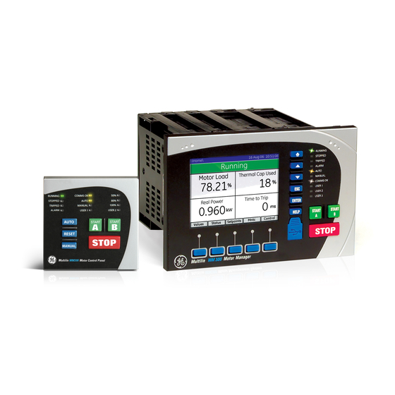
Page 9: For Further Assistance
Website: http://www.gegridsolutions.com/multilin Description of the MM300 Motor Management system The MM300 can be equipped with either of two control panels, or with no control panel. • Basic control panel: includes pushbuttons for Stop, Start A, Start B, Auto, Manual, and Reset, and 12 LED status indicators. - Page 10 Undercurrent and underpower Bearing temperature RTD Current unbalance Voltage phase reversal Thermal overload Ground instantaneous overcurrent Ground time overcurrent Locked/stalled rotor, mechanical jam Overvoltage, three-phase Starts per hour and time between starts 1–4 MM300 MOTOR MANAGEMENT SYSTEM – INSTRUCTION MANUAL...
-
Page 11: Mm300 Order Codes
CHAPTER 1: INTRODUCTION OVERVIEW Figure 1-2: MM300 feature overview MM300 order codes The information to specify an MM300 relay is provided in the following order code figure. Figure 1-3: MM300 order codes Base Expanded MM300 – * Interface MM300 MM300 Motor Management System... -
Page 12: Example Of An Mm300 Order Code
CHAPTER 1: INTRODUCTION Example of an MM300 order code MM300-GEHS1CAXXXX: MM300 with graphical control panel and USB port, English language display, high voltage 84 to 250 V DC and 60 to 300 V AC power supply, RS485 Modbus RTU communications, starter control, event recorder, undervoltage autorestart, three-phase current, thermal overload, undercurrent, single phase underpower, two 10 A form-A contact output relays, and six digital inputs. - Page 13 Pickup level: ............1 to 100% of FLA in steps of 1 Time delay: ............1 to 60 seconds in steps of 1 Timing accuracy: ..........±500 ms Elements: ..............trip and alarm MM300 MOTOR MANAGEMENT SYSTEM – INSTRUCTION MANUAL 1–7...
-
Page 14: User Interface Specifications
Long Dip Delay: ........... 1.0 to 1200.0 s in steps of 1.0 s Short Dip Time Accuracy:....... ±5% of total time Medium and Long Dip Time Accuracy:..±1 s or ±5% of total time, whichever is greater 1–8 MM300 MOTOR MANAGEMENT SYSTEM – INSTRUCTION MANUAL... -
Page 15: Inputs Specifications
Nominal frequency: ........... 50 or 60 Hz Accuracy:..............±2% of reading, or ±1 V, whichever is greater RTD INPUTS Sensor type: ............Three-wire RTD (100 ohm Platinum) Sensing current:........... 5 mA Accuracy:..............±3°C MM300 MOTOR MANAGEMENT SYSTEM – INSTRUCTION MANUAL 1–9... -
Page 16: Outputs Specifications
Modes: ..............slave (125, 250, and 500 kbps) Connector: ............. 5-pin terminal Current Draw:............80 mA @ 24 VDC ETHERNET (COPPER) Modes: ..............10/100 MB (auto-detect) Connector: ............. RJ-45 SNTP clock synchronization error:....<200 ms (typical) Protocol:..............Modbus TCP 1–10 MM300 MOTOR MANAGEMENT SYSTEM – INSTRUCTION MANUAL... - Page 17 Isolation:..............2 kV USB PORT (GRAPHIC CONTROL PANEL ONLY) Standard specification: ........Compliant with both USB 2.0 and USB 1.1 Data transfer rate:..........USB device emulating serial communications port at 115 kbps MM300 MOTOR MANAGEMENT SYSTEM – INSTRUCTION MANUAL 1–11...
-
Page 18: Testing And Certification
EMC Directive EN50263 / EN61000-6-2/ EN61000-6-4 North America: cULus UL1053 [e83849 NKCR] UL508 [e83849 NKCR] C22.2-14 [e83849 NKCR7] Machines and Equipment TR CU 010/2011 ISO: Manufactured under a registered ISO9001 quality program 1–12 MM300 MOTOR MANAGEMENT SYSTEM – INSTRUCTION MANUAL... -
Page 19: Physical Specifications
IEC60068-2-30 Variant 2, 6days) Altitude: 2000m (max) Overvoltage Category: Ingress Protection: IP20 (Base Unit) IP54 (Control Panel) Environmental rating: C surrounding air Pollution Degree: Type 1 (panel mount versions only) Noise: 0 dB MM300 MOTOR MANAGEMENT SYSTEM – INSTRUCTION MANUAL 1–13... - Page 20 SPECIFICATIONS CHAPTER 1: INTRODUCTION 1–14 MM300 MOTOR MANAGEMENT SYSTEM – INSTRUCTION MANUAL...
-
Page 21: Dimensions
Dimensions The MM300 is packaged in a modular arrangement. The dimensions of the MM300 are shown below. Additional dimensions for mounting and panel cutouts are shown in the following sections. MM300 MOTOR MANAGEMENT SYSTEM – INSTRUCTION MANUAL... -
Page 22: Product Identification
5.550” (140,97 mm) 853724A1.CDR Product identification The product identification label is located on the side panel of the MM300. This label indicates the product model, serial number, firmware revision, and date of manufacture. Figure 2-2: MM300 label 2.425” (61.6 mm) -
Page 23: Mounting
CHAPTER 2: INSTALLATION MECHANICAL INSTALLATION Mounting The MM300 can be mounted three ways: standard panel mount, DIN rail mount, and screw mount for high vibration environments. The standard panel mount and cutout dimensions are illustrated below. Figure 2-3: Base Unit standard panel mounting and cutout dimensions #4 - 40x3/8in SELF-TAP PAN HD PHILIPS QTY: 6 (SUPPLIED);... - Page 24 TypX8 853825A1.cdr Figure 2-5: DIN rail mounting - Base and Expansion units SNAP-IN THE DIN CLIPS (QTY: 4) FOR DIN RAIL MOUNTING 0.30” (7,6 mm) 1.38” (35,1 mm) DIN 3 RAIL 853726A1.CDR 2–4 MM300 MOTOR MANAGEMENT SYSTEM – INSTRUCTION MANUAL...
- Page 25 [9.03 mm] 0.672” 2.285” [17.06 mm] [58.04 mm] EXPANSION UNIT OUTLINE #6-32 THREADED HOLE QTY: 2 1.500” [38.10 mm] #6-32X1/2 FT FLAT HEAD PHIL ZINC 853755A2.cdr QTY: 2; TIGHTENING TORQUE: 10 lb. in. MM300 MOTOR MANAGEMENT SYSTEM – INSTRUCTION MANUAL 2–5...
-
Page 26: Module Withdrawal And Insertion
MM300. The MM300 is a modular protection system. This allows for easy withdrawal and insertion of modules for fast replacement. Modules must only be replaced in their original factory configured slots. -
Page 27: Module And Terminal Identification
MECHANICAL INSTALLATION Figure 2-9: Inserting modules into the MM300 853734A1.CDR Module and terminal identification The MM300 input/output and protection modules are labeled with the “IO_” prefix followed by a one-character identifier as follows. Table 2-1: Input/output module nomenclature Module Description... -
Page 28: Electrical Installation
• voltage inputs 853740A2.CDR The MM300 can contain up to eight modules. The first four modules (slots A through D) comprise the base unit, and the next four modules (slots E through H) comprise the optional expanded unit. Table 2-2: Module slot position... -
Page 29: Power Supply Module
60 to 300 V AC or 84 to 250 V DC is required to power the MM300. For the low voltage version, 20 V DC to 60 V DC is required to power the MM300. -
Page 30: Cpu Module
The optional communications board provides Fieldbus and Ethernet ports. Ground current input The MM300 CPU module has a sensitive ground input suitable for a 50:0.025 CT. There is also a residual ground input on the CT module (IO_A) with the same rating as the phase current inputs. - Page 31 CT WINDOW. 50:0.025 CORE BALANCE CT FOR GROUND SENSING CORE BALANCE CT SECONDARY CONNECTION TO MM300 IED TO STARTER (TWISTED PAIR) GROUND BUS POWER CABLE TO MOTOR BOTTOM OF MOTOR STARTER COMPARTMENT 853712A1.CDR MM300 MOTOR MANAGEMENT SYSTEM – INSTRUCTION MANUAL 2–11...
-
Page 32: Thermistor Connections
+ and - terminals on the CPU module. By specifying the hot and cold thermistor resistance, the MM300 automatically determines the thermistor type as NTC or PTC. Use thermistors with hot and cold resistance values in the range 100 to 30000 ohms. -
Page 33: Rs485 Connections
DEVICE 853745A1.CDR One two-wire RS485 port is provided. Up to 32 MM300 IEDs can be daisy-chained together on a communication channel without exceeding the driver capability. For larger systems, additional serial channels must be added. Commercially available repeaters can also be used to add more than 32 relays on a single channel. -
Page 34: Protection Modules
CAUTION: that the common terminals of each RS485 port are tied together and grounded only once, at the master or at the MM300. Failure to do so may result in intermittent or failed communications. The source computer/PLC/SCADA system should have similar transient protection devices installed, either internally or externally. -
Page 35: Phase Current Inputs (Io_A Module)
Motor Management System 853744A2.CDR The MM300 has three channels for phase current inputs, each with an isolating transformer. The phase CTs should be chosen so the FLA is not less than 50% of the rated phase CT primary. Ideally, the phase CT primary should be chosen such that the FLA is 100% of the phase CT primary or slightly less, never more. - Page 36 In the event of a single phase, there will always be a large unbalance present at the interposing CTs of the relay. If for example phase A was lost, phase A would read zero 2–16 MM300 MOTOR MANAGEMENT SYSTEM – INSTRUCTION MANUAL...
-
Page 37: Phase Voltage Inputs (Io_B Module)
B. Phase voltage inputs The MM300 has three channels for AC voltage inputs. There are no internal fuses or ground (IO_B module) connections on the voltage inputs. Polarity is critical for correct power measurement and voltage phase reversal operation. -
Page 38: Input/Output Modules
The type IO_G module contains three PT100 RTDs and associated protection functionality. connections (IO_G The MM300 monitors up to six RTD inputs for stator, bearing, ambient, or other module) temperature monitoring types. The type of each RTD is 100 ohm platinum (DIN 43760). -
Page 39: Type Io_C Module Connections
The two contact outputs can be programmed to follow any one of the digital signals developed by the MM300, such as alarms and status signals. The exception is that the contactor A relay is fixed as the first contact output, and contactor B relay is fixed as the second contact output (where used). -
Page 40: Type Io_C Module Connections
The IO_D module contains four form-C contact output relays. connections In general, contact outputs can be programmed to follow any one of the digital signals developed by the MM300, such as alarms and status signals. Figure 2-24: Typical wiring for type IO_D contact output module MM300... -
Page 41: Type Io_E Module Connections
The two contact outputs can be programmed to follow any one of the digital signals developed by the MM300, such as alarms and status signals. The exception is that the contactor A relay is fixed as the first contact output, and contactor B relay is fixed as the second contact output (where used). -
Page 42: Dielectric Strength Testing
POT”) with the MM300 installed. The MM300 with the I/O Module type C installed (see below) is rated for 1.9 kV AC for 1 second, or 1.6 kV AC for 1 minute (per UL 508) isolation between relay contacts, CT inputs, VT inputs and the surge ground terminal SG. - Page 43 RS485 communication ports are not to be tested for dielectric strength under any circumstance (see above). Substitute the slot position of the Input/Output module (E, F, G, or H) wherever the tilde NOTE: symbol “~” appears in the diagram above. NOTE MM300 MOTOR MANAGEMENT SYSTEM – INSTRUCTION MANUAL 2–23...
-
Page 44: Starter Types
Figure 2-28: Full-voltage non-reversing starter wiring - IO_C GE Multilin Contactor Reset Field Start MM300 Field Stop Low Voltage Motor Manager Core Balance CT MOTOR RS485 Serial Link Ground at one point 853704A3.cdr Stator Thermistor 2–24 MM300 MOTOR MANAGEMENT SYSTEM – INSTRUCTION MANUAL... - Page 45 M drops out, and the motor stops. The pre-contactor is omitted on forced starts (for example, UVR Immediate, External Start). Connect AUX VT to the Control Supply for correct operation of the UV Restart feature and NOTE: correct input readings. NOTE MM300 MOTOR MANAGEMENT SYSTEM – INSTRUCTION MANUAL 2–25...
-
Page 46: Full-Voltage Reversing Starter
Figure 2-30: Full-voltage reversing starter wiring - IO_C GE Multilin Rev Limit MM300 Fwd Limit Field Stop Low Voltage Motor Manager Dual Contactor Inter- lock Core Balance CT 853705A3.cdr MOTOR RS485 Serial Link Ground at one point Stator Thermistor 2–26 MM300 MOTOR MANAGEMENT SYSTEM – INSTRUCTION MANUAL... - Page 47 Forced starts are not supervised by this starter transfer timer – any external starting circuit must itself respect fast direction change restrictions. Connect AUX VT to the Control Supply for correct operation of the UV Restart feature and NOTE: correct input readings. NOTE MM300 MOTOR MANAGEMENT SYSTEM – INSTRUCTION MANUAL 2–27...
-
Page 48: Two-Speed Starter
GE Multilin Dual Contactor Field Start High Field Start Low MM300 Field Stop Low Voltage Motor Manager Core Balance Inter- lock MOTOR RS485 Serial Link Ground at one point 853706A3.cdr Stator Thermistor 2–28 MM300 MOTOR MANAGEMENT SYSTEM – INSTRUCTION MANUAL... - Page 49 Connect AUX VT to the Control Supply for correct operation of the UV Restart feature and NOTE: correct input readings. NOTE MM300 MOTOR MANAGEMENT SYSTEM – INSTRUCTION MANUAL 2–29...
-
Page 50: Wye-Delta Open Transition Starter
Figure 2-34: Wye-delta open transition starter wiring - IO_C Module GE Multilin Dual Field Start MM300 Contactor Field Stop Low Voltage Motor Manager Core Balance Inter- lock RS485 Serial Link Ground at one point 853707A3.cdr Stator Thermistor 2–30 MM300 MOTOR MANAGEMENT SYSTEM – INSTRUCTION MANUAL... - Page 51 – any external type B starting circuit must itself respect full voltage starting restrictions. Connect AUX VT to the Control Supply for correct operation of the UV Restart feature and NOTE: correct input readings. NOTE MM300 MOTOR MANAGEMENT SYSTEM – INSTRUCTION MANUAL 2–31...
-
Page 52: Inverter Starter (Vfd, Vsd)
Motor Running Output INVERTER Ramp Input GE Multilin Reset MM300 Field Start Field Stop Low Voltage Motor Manager Core Balance CT MOTOR RS485 Serial Link Ground at one point 853708A3.cdr Stator Thermistor 2–32 MM300 MOTOR MANAGEMENT SYSTEM – INSTRUCTION MANUAL... - Page 53 Drive Stop Fail alarm is generated. Neither results in a trip or a stop. The Drive Start Failed alarm is latched until reset or cleared by a stop control. The Inverter Fail alarm is cleared at next start. MM300 MOTOR MANAGEMENT SYSTEM – INSTRUCTION MANUAL 2–33...
-
Page 54: Soft Starter Type
Up To Speed Output SOFT STARTER GE Multilin Stop Reset MM300 Field Start Field Stop Low Voltage Motor Manager Core Balance CT MOTOR RS485 Serial Link Ground at one point 853709A3.cdr Stator Thermistor 2–34 MM300 MOTOR MANAGEMENT SYSTEM – INSTRUCTION MANUAL... - Page 55 The Undervoltage Autorestart feature is disabled for the Soft Starter. Connect AUX VT to the Control Supply for correct operation of the UV Restart feature and NOTE: correct input readings. NOTE MM300 MOTOR MANAGEMENT SYSTEM – INSTRUCTION MANUAL 2–35...
-
Page 56: Autotransformer Open Transition Starter
STARTER TYPES CHAPTER 2: INSTALLATION Ensure soft starter is located before contactor. NOTE: NOTE Autotransformer open transition starter Figure 2-40: Autotransformer open transition starter typical wiring - IO_C (expansion module in slot "E") 2–36 MM300 MOTOR MANAGEMENT SYSTEM – INSTRUCTION MANUAL... - Page 57 Autotransformer open transition starter is a reduced voltage starter. Three motor contactors R, 1S and 2S each controlled by a separate MM300 output relay are used to perform this function. There are two options of this starter: 1S-2S and 2S-1S. For more details please refer to chapter Autotransformer open transition starter in section Configuration setpoints / Motor setpoins section of the manual.
-
Page 58: Autotransformer Closed Transition Starter
STARTER TYPES CHAPTER 2: INSTALLATION Autotransformer closed transition starter Figure 2-42: Autotransformer closed transition starter typical wiring - IO_C (expansion module in slot "E") 2–38 MM300 MOTOR MANAGEMENT SYSTEM – INSTRUCTION MANUAL... - Page 59 Autotransformer closed transition starter is a reduced voltage starter. Three motor contactors R, 1S and 2S each controlled by a separate MM300 output relay are used to perform this function. There are two options of this starter: 1S-2S and 2S-1S. For more details please refer to chapter Autotransformer open transition starter in section Configuration setpoints / Motor setpoints section of the manual.
-
Page 60: Maintenance
Maintenance The MM300 requires minimal maintenance. As a microprocessor-based relay, its characteristics do not change over time. The expected service life of an MM300 is 20 years when the environment and electrical conditions are within stated specifications. While the MM300 performs continual self-tests, it is recommended that maintenance be scheduled with other system maintenance. -
Page 61: Interfacing With The Mm300
• Interfacing via the EnerVista MM300 Setup software. This section provides an overview of the interfacing methods available with the MM300 using the Graphical and Basic control panels. For additional details on interface parameters (for example, settings, actual values, etc.), refer to the individual chapters. -
Page 62: Graphical Display
GRAPHICAL CONTROL PANEL CHAPTER 3: INTERFACING WITH THE MM300 Figure 3-1: MM300 front panel with example default display Graphical display Each display page consists of the three components shown below. Figure 3-2: Graphical display overview The header bar (white text on a blue background) displays the hierarchical path name, the date and time in 24-hour format, and the current password access level. -
Page 63: Keypad
Subsequent presses tab up and down through the fields, scrolling as required. • When a field is open for editing, the UP and DOWN keys increment/decrement the value of that field. MM300 MOTOR MANAGEMENT SYSTEM – INSTRUCTION MANUAL 3–3... - Page 64 Pressing an invalid key displays a message explaining the problem and recommending a solution. Where the keypress is invalid because a security passcode is required, the dialog window will be a passcode entry window. 3–4 MM300 MOTOR MANAGEMENT SYSTEM – INSTRUCTION MANUAL...
-
Page 65: Control Keys
START A and START B: Pressing these keys initiates the programmed start sequence. The START A and START B keys are used to start the motor from the MM300 faceplate (if MCC control is enabled). The start A and start B sequences can also be initiated via communications, field control, or hardwired input. -
Page 66: Mm300 Graphical Display Pages
GRAPHICAL CONTROL PANEL CHAPTER 3: INTERFACING WITH THE MM300 MM300 graphical display pages A summary of the MM300 page hierarchy is shown below. Figure 3-6: MM300 display page hierarchy Motor CT-VT Summary Values Inputs Amps Outputs Volts Trips Comms Power... -
Page 67: Home Display Page
Some typical actual values screens are shown below. MM300 MOTOR MANAGEMENT SYSTEM – INSTRUCTION MANUAL 3–7... -
Page 68: Status Pages
Outputs (displays the present state of assigned contact outputs). • System (displays the present state of the communications interface). • Flex (displays the present state of the FlexLogic™ engine and number of lines used.) A typical display is shown below: 3–8 MM300 MOTOR MANAGEMENT SYSTEM – INSTRUCTION MANUAL... -
Page 69: Setpoints Pages
Protection (contains the protection setpoints) • Control (contains the control setpoints) • Security (contains the password security setpoints) • Factory (contains settings used by GE Multilin personnel for testing and calibration purposes.) MM300 MOTOR MANAGEMENT SYSTEM – INSTRUCTION MANUAL 3–9... -
Page 70: Diagnostics Pages
If all ten process interlock functions are disabled, the MM300 will display only 10 successive “Disabled” list items. If one of the interlock functions were then enabled, then room is made on the display for the six setpoints which are now functional. - Page 71 Figure 3-14: Typical phasors page Figure 3-15: Typical events page Pressing Enter on the highlighted line (line 9 above) will take you directly into the detailed event analysis screen: Figure 3-16: Typical event diagnosis page MM300 MOTOR MANAGEMENT SYSTEM – INSTRUCTION MANUAL 3–11...
-
Page 72: Control Page
Figure 3-18: Typical invalid operation popup window Help and illegal action popup windows remain open until they are acknowledged by clicking any soft or hard key, or until a pre-determined period of inactivity has passed. 3–12 MM300 MOTOR MANAGEMENT SYSTEM – INSTRUCTION MANUAL... -
Page 73: Mm300 Programming Techniques
Figure 3-20: Numeric setpoint editor window MM300 MOTOR MANAGEMENT SYSTEM – INSTRUCTION MANUAL 3–13... -
Page 74: Alphanumeric Setpoints
When an alphanumeric setpoint is selected, the MM300 displays an alphanumeric setpoint editor window. Figure 3-21: Alphanumeric setpoint editor A flashing underline marks the current character. The “<” and “>” soft-keys shift the cursor left and right. -
Page 75: Security Access
(for example, in entering factory page at read only security access). Figure 3-23: Password entry dialog box The encrypted key information appears only when the current security access level is 0. MM300 MOTOR MANAGEMENT SYSTEM – INSTRUCTION MANUAL 3–15... -
Page 76: Basic Control Panel
CHAPTER 3: INTERFACING WITH THE MM300 Basic control panel The MM300 basic control panel provides the basic start and stop panel functionality, as well as a series of LED indications. The basic control panel is illustrated below. Figure 3-24: Basic control panel 853750A1.CDR... -
Page 77: Software
The EnerVista MM300 Setup software can run without a MM300 connected to the computer. In this case, settings may be saved to a file for future use. If an MM300 is connected to a PC and communications are enabled, the MM300 can be programmed from the setting screens. - Page 78 CHAPTER 3: INTERFACING WITH THE MM300 Check the Setup Software for the availability of the USB Device on the Device setup Window. It will automatically reappear on the ‘USB Device’ list as ‘MM300 USB Serial Emulation (COM #)’ as shown in the image below.
- Page 79 If problem still persists, uninstall the USB driver from Computer’s ‘Device Manager’ under tree-branch modems from the Installation folder. To uninstall it, right click on MM300 USB Serial Emulation and select Uninstall. After the uninstall, remove the USB cable from the Device’s native USB port, wait for at least 10 Seconds and reconnect it.
-
Page 80: Installing The Enervista Mm300 Setup Software
Installing the After ensuring the minimum requirements indicated earlier, use the following procedure to EnerVista MM300 install the EnerVista MM300 Setup software from the enclosed GE EnerVista CD. Setup software Insert the GE EnerVista CD into your CD-ROM drive. Click the Install Now button and follow the installation instructions to install the no- charge EnerVista software on the local PC. - Page 81 In the EnerVista Launchpad window, click the Add Product button and select the MM300 Motor Management System as shown below. Select the Web option to ensure the most recent software release, or select CD if you do not have a web connection, then click the Add Now button to list software items for the MM300.
- Page 82 If you are going to communicate from your computer to the MM300 Relay using the USB port: 10. Plug the USB cable into the USB port on the MM300 Relay then into the USB port on your computer. The following screen will appear: 3–22...
- Page 83 11. Select Install... Automatically 12. Select No, not this time. The above Hardware Installation warning screen (see #8 above) will reappear. Press the Continue Anyway button. 13. In EnerVista > Device Setup: MM300 MOTOR MANAGEMENT SYSTEM – INSTRUCTION MANUAL 3–23...
-
Page 84: Upgrading The Software
The latest EnerVista software and firmware can be downloaded from: software https://www.gegridsolutions.com/app/ViewFiles.aspx?prod=mm300&type=7 After upgrading, check the version number under Help > About. If the new version does not display, try uninstalling the software and reinstalling the new versions. 3–24 MM300 MOTOR MANAGEMENT SYSTEM – INSTRUCTION MANUAL... -
Page 85: Connecting Enervista Mm300 Setup To The Relay
Select “Serial Device” from the Interface drop-down list. Click the Read Order Code button to connect to the MM300 device and upload the order code. Click OK when the relay order code has been received. The new device will be added to the Site List window (or Online window) located in the top left corner of the main EnerVista MM300/MM200 Setup window. -
Page 86: Using The Quick Connect Feature
As indicated by the window, the "Quick Connect" feature can quickly connect the EnerVista MM300/MM200 Setup software to a MM300 front port if the USB is selected in the interface drop-down list. Select "MM300 Relay" and press the Connect button. -
Page 87: Working With Setpoints And Setpoint Files
Working with setpoints and setpoint files Engaging a device The EnerVista MM300/MM200 Setup software may be used in on-line mode (relay connected) to directly communicate with a relay. Communicating relays are organized and grouped by communication interfaces and into sites. Sites may contain any number of relays selected from the product series. - Page 88 Select the desired value from this list. For setpoints requiring an alphanumeric text string (e.g. "relay name"), the value may be entered directly within the setpoint value box. 3–28 MM300 MOTOR MANAGEMENT SYSTEM – INSTRUCTION MANUAL...
-
Page 89: File Support
In the Setpoint > Config > CT-VT dialog box, click on Save to save the values into the MM300 . Click YES to accept any changes and exit the window. Click Restore to retain previous values. Click Default to restore Default values. -
Page 90: Adding Setpoints Files To The Environment
SOFTWARE CHAPTER 3: INTERFACING WITH THE MM300 Adding setpoints files The EnerVista MM300/MM200 Setup software provides the capability to review and to the environment manage a large group of setpoint files. Use the following procedure to add an existing file to the list. -
Page 91: Creating A New Setpoints File
Select the file name and path to store the file, or select any displayed file name to replace an existing file. All MM300 setpoints files should have the extension ‘M30’ (for example, ‘ExerciserStatus.M30’). Click OK to complete the process. Once this step is completed, the new file, with a complete path, will be added to the EnerVista MM300/MM200 Setup software environment. -
Page 92: Upgrading Setpoint Files To A New Revision
It is often necessary to upgrade the revision for a previously saved setpoint file after the files to a new revision MM300 firmware has been upgraded. This is illustrated in the following procedure: Establish communications with the MM300 relay. Select the Online > Device Setup menu item and record the Firmware Revision from the Device Setup window. -
Page 93: Printing Setpoints And Actual Values
CHAPTER 3: INTERFACING WITH THE MM300 SOFTWARE Printing setpoints and The EnerVista MM300/MM200 Setup software allows the user to print partial or complete actual values lists of setpoints and actual values. Use the following procedure to print a list of setpoints: Select a previously saved setpoints file in the File pane or establish communications with a MM300 device. -
Page 94: Printing Actual Values From A Connected Device
The unit can be decommissioned by turning off the power to the unit and disconnecting clearing data the wires to it. Files can be cleared after uninstalling the EnerVista software or MM300 device, for example to comply with data security regulations.On the computer, settings files can be identified by the .m30 extension. -
Page 95: Upgrading Relay Firmware
If you are using the MM300 Graphical Control Panel (GCP) or Hand Held Device (HHD), connect the USB port on the front of the MM300 relay, to the USB port on the local PC, using a USB 2.0 type A to mini B cable. This configuration (1) is shown below. - Page 96 Click Windows Start Button > Control Panel > System > Hardware tab. Then click Device Manager. Once your physical connections are complete and you have determined which COM PORT you will be using, start your MM300/MM200 EnerVista Setup Program. Save the setpoints to a file as shown in Downloading and Saving Setpoints Files.
- Page 97 EnerVista MM300/MM200 Setup software now prepares the MM300 to receive the new firmware file. While the file is being loaded into the MM300 a status box appears showing how much of the new firmware file has been transferred and the upgrade status. The entire transfer process takes approximately 10 minutes.
-
Page 98: Power Analysis
The EnerVista MM300 Setup software can be used to capture waveforms (or view trace memory) from the MM300 relay at the instance of a trip, activation of a virtual output, or other conditions. A maximum of 64 cycles (32 samples per cycle) can be captured and the trigger point can be adjusted to anywhere within the set cycles. - Page 99 From the window main menu bar, press the Preference button to open the COMTRADE Setup page, in order to change the graph attributes. The following window will appear: MM300 MOTOR MANAGEMENT SYSTEM – INSTRUCTION MANUAL 3–39...
- Page 100 CHAPTER 3: INTERFACING WITH THE MM300 To change graph attributes for the Analog Channels select it from the menu tree. To change the graph attributes for the Digital Channels select it from the menu tree. 3–40 MM300 MOTOR MANAGEMENT SYSTEM – INSTRUCTION MANUAL...
- Page 101 Osc Data, Phasor Data or Harmonics Data button. For each button pressed the corresponding window is displayed as follows: 12. Use the graph attribute utility described in step 10, to change the vector colors in the vector displays. MM300 MOTOR MANAGEMENT SYSTEM – INSTRUCTION MANUAL 3–41...
-
Page 102: Data Logger
Disabled Viewing and saving of the Datalogger is performed as follows: With EnerVista MM300 Setup running and communications established, select the Diagnostics > Datalog menu item to open the datalog setup window: If Continuous mode is enabled, click on Stop to stop the datalog Click on the Save to File button to save the datalog to the local PC. - Page 103 The method of customizing the datalog view is the same as the Waveform Capture described above. The datalog can be set to capture another buffer by clicking on Run (when Continuous mode is enabled), or by clicking on Release (when Continuous mode is disabled). MM300 MOTOR MANAGEMENT SYSTEM – INSTRUCTION MANUAL 3–43...
- Page 104 SOFTWARE CHAPTER 3: INTERFACING WITH THE MM300 3–44 MM300 MOTOR MANAGEMENT SYSTEM – INSTRUCTION MANUAL...
-
Page 105: Actual Values
Actual values may be accessed via one of the following methods. • Through the graphical control panel, using the keys and display. • With the EnerVista MM300 Setup software supplied with the relay. • Through the RS485 or Ethernet ports and a PLC/SCADA system running user-written software. -
Page 106: Metering
Figure 4-2: Current metering page Voltage metering Select the Values > Volts page to display the metered voltage for all three phases and auxiliary. The system frequency is also displayed. Figure 4-3: Voltage metering page 4–2 MM300 MOTOR MANAGEMENT SYSTEM – INSTRUCTION MANUAL... -
Page 107: Power Metering
Select the Values > Power page to display the power and energy metering values. Figure 4-5: Power metering display An induction motor by convention consumes watts and vars (+watts and +vars). NOTE: NOTE MM300 MOTOR MANAGEMENT SYSTEM – INSTRUCTION MANUAL 4–3... -
Page 108: Sensor Metering
Select the Values > Sensor page to display the metered temperature sensor values. The values for each RTD and thermistor (if installed) are displayed. Note that the MM300 also records the maximum temperature measured for each RTD since the last clear. -
Page 109: Status
CHAPTER 4: ACTUAL VALUES STATUS Status The MM300 status messages are categorized as trip, alarm, and stop messages. The following trip, alarm, and stop messages are displayed. Status messages Figure 4-7: Typical status message display Color indicates message type: •... -
Page 110: System Page
CHAPTER 4: ACTUAL VALUES System Page Shows the communication status of all configuration interfaces (serial, Ethernet, DeviceNet, and Profibus). Flex Page Shows the status of Flex engine and the number of 512 lines in use. 4–6 MM300 MOTOR MANAGEMENT SYSTEM – INSTRUCTION MANUAL... -
Page 111: Understanding Setpoints
The soft-keys on the Home > Setpoints page open pages two levels down, since the pages immediately below this page are blank. For example, the Config soft-key opens the Home > Setpoints > Config > Motor page. MM300 MOTOR MANAGEMENT SYSTEM – INSTRUCTION MANUAL 5–1... -
Page 112: Setting Text Abbreviations
%NCV: percent of nominal control voltage • %MNR: percent of motor nominal rating • Ctrl: control • Hr & hr: hour • O/L: overload • UTC: co-ordinated universal time • ops: operations • mcc: motor control center 5–2 MM300 MOTOR MANAGEMENT SYSTEM – INSTRUCTION MANUAL... -
Page 113: Configuration Setpoints
Events (setpoints related to the event recorder) • Counters (setpoints related to the digital counters) Motor setpoints The MM300 starter function is responsible for executing the motor startup sequence, including the pre-contactor start warning. The MM300 provides eight pre-defined starters. • Full-voltage non-reversing •... -
Page 114: Common Motor Setpoints
Motor Rating (Mandatory Setpoint) Range: 0.3 to 1100.0 kW in steps of 0.1 or OFF Default: OFF This setpoint specifies the motor rating (or low speed motor rating for two-speed starters) in kWs. 5–4 MM300 MOTOR MANAGEMENT SYSTEM – INSTRUCTION MANUAL... - Page 115 T - Transfer Time setting R - Ramp Down Time setting Motor Current Contactor A Relay Contactor B Relay Pre-contactor Starting Running Motor Current Contactor A Relay Contactor B Relay Pre-contactor Starting Running Stopping 853710A3.CDR MM300 MOTOR MANAGEMENT SYSTEM – INSTRUCTION MANUAL 5–5...
- Page 116 CONFIGURATION SETPOINTS CHAPTER 5: SETPOINTS Figure 5-4: Typical starter timing (2 of 2) The following sections provide additional information for each starter type. 5–6 MM300 MOTOR MANAGEMENT SYSTEM – INSTRUCTION MANUAL...
-
Page 117: Full-Voltage Non-Reversing Starter
Forced starts are not supervised by this starter transfer timer – any external starting circuit must itself respect fast direction change restrictions. The following figure illustrates typical starter timing beginning from the stopped state. MM300 MOTOR MANAGEMENT SYSTEM – INSTRUCTION MANUAL 5–7... -
Page 118: Two-Speed Starter
Forced starts are not supervised by this starter transfer timer – any external starting circuit must itself respect high to low speed transition restrictions and starting in high speed restrictions. The following figure illustrates typical starter timing beginning from the stopped state. 5–8 MM300 MOTOR MANAGEMENT SYSTEM – INSTRUCTION MANUAL... -
Page 119: Wye-Delta Open Transition Starter
Range: 0.3 to 1100.0 kW in steps of 0.1 or OFF Default: OFF This setpoint specifies the high-speed motor rating for two-speed starters in kWs on the line. This setpoint is for reference only and does not affect operation of the MM300. High Speed Start Block Range: Enabled, Disabled Default: Enabled When this setpoint is programmed as “Disabled”, the relay allows the motor to be... -
Page 120: Inverter Starter
1M. This provides power for the inverter to start up. Relay2 closes after a 1 second delay, and seals in, which signals the 5–10 MM300 MOTOR MANAGEMENT SYSTEM – INSTRUCTION MANUAL... - Page 121 An audible or other warning signal can be activated in this interval by connecting the signal to a contact output set to the pre-contactor function. MM300 MOTOR MANAGEMENT SYSTEM – INSTRUCTION MANUAL 5–11...
-
Page 122: Soft Starter
Contactor A relay Contactor B relay Pre-contactor Starting Running Stopping P = Pre-contactor time setting R = Ramp Down time setting 853721A3.CDR The following additional setpoints are available for the soft starter. 5–12 MM300 MOTOR MANAGEMENT SYSTEM – INSTRUCTION MANUAL... -
Page 123: Autotransformer Open Transition Starter
Autotransformer open transition starter is used. Three motor contactors R, 1S and 2S each controlled by a separate MM300 output relay are used to perform this function. There are two options of this starter: 1S-2S and 2S-1S. Each one offers a slightly different sequence of contactors operation. - Page 124 Wait until contactor 1S open status is received. Close and maintain contactor R. Full voltage is applied to the motor. Stop/trip sequence: Stop command received by the MM300 or a trip occurs. Open Contactor R. Open Contactors 1S and 2S if they are not already opened.
-
Page 125: Autotransformer Closed Transition Starter
Autotransformer closed transition starter is used. Three motor contactors R, 1S and 2S each controlled by a separate MM300 output relay are used to perform this function. There are two options of this starter: 1S-2S and 2S-1S. Each one offers a slightly different sequence of contactors operation. - Page 126 10. Open contactor 2S. 2S-1S start sequence: Start A command received by the MM300 (serial, digital input or faceplate). Wait for the time set in Pre-Contactor Time setpoint. Close and maintain contactor 2S. Reduced voltage is applied to the motor.
- Page 127 Open Ctrl Cct and Welded Contactor to the status of contactor 2S. It is recommended to check the specifications of the autotransformer used for this NOTE: application and adjust the MM300 setpoint Starts/Hour Limit if necessary [Path: Home > Setpoints > Control > Inhibits]. NOTE Pre-contactor is omitted on forced starts (for example, UVR Immediate, External Start).
-
Page 128: Current And Voltage Transformers
This setpoint is displayed only if the phase CT type is set to 1 A secondary or 5 A NOTE: secondary and the motor starter type is two-speed. NOTE 5–18 MM300 MOTOR MANAGEMENT SYSTEM – INSTRUCTION MANUAL... - Page 129 CT Primary with several turns thereby increasing the current seen by the MM300 and as a result increasing the accuracy of the measurement. The value of this setting should equal the number of turns on the CT Primary to display the correct current value.
-
Page 130: Inputs
CONFIGURATION SETPOINTS CHAPTER 5: SETPOINTS Inputs The MM300 digital (contact) inputs are programmed in this menu. A typical input configuration page is shown below. Figure 5-16: Input configuration setpoint page Inputs are automatically assigned based on typical wiring diagrams, shown in chapter 2, NOTE: when a pre-defined starter is selected. - Page 131 When “Test switch” is kept asserted, the device enters into “Test Mode”. While MM300 is in “Test Mode”, the starting inhibit counters are bypassed. Undercurrent, undervoltage and underpower functions can also be blocked in Test Mode by enabling the setting 'PRT Func Ignore in Test Mode'.
-
Page 132: Outputs
• FlexLogic™ operands: Any FlexLogic™ operand can be assigned to a contact output. Select Home > Setpnts > CFG > Outputs > Trips to edit the Trips setpoints: 5–22 MM300 MOTOR MANAGEMENT SYSTEM – INSTRUCTION MANUAL... - Page 133 This setting assigns the Drive Available Manual element to the desired contact output. Drive Available Auto Range: N/A, C2, D1... D4 (order code dependent) Default: N/A This setting assigns the Drive Available Auto element to the desired contact output. MM300 MOTOR MANAGEMENT SYSTEM – INSTRUCTION MANUAL 5–23...
-
Page 134: Communications Setpoints
NOTE Communications setpoints The MM300 has one RS485 serial communications port supporting a subset of the Modbus protocol. An additional DeviceNet, Profibus, or Ethernet port is also available as an option. Select the Home > Setpnts > Cfg > Comms page to edit the communications setpoints. - Page 135 Range: 1 to 254 in steps of 1 Default: 254 For RS485 communications, each MM300 IED must have a unique address from 1 to 254. Address 0 is the broadcast address detected by all IEDs in the serial link. Addresses do not have to be sequential, but no two units can have the same address or errors will occur.
-
Page 136: System
Range: Default Map, 1 Register to 95 Registers Default: Default Map This setpoint specifies the number of Modbus User Map registers to be read as part of FieldBus Input Data. System Figure 5-22: System setpoint page 5–26 MM300 MOTOR MANAGEMENT SYSTEM – INSTRUCTION MANUAL... - Page 137 This setpoint defines whether a self-test failure will cause a trip or an alarm. For relay self-test, the MM300 runs a series of self-tests, including data and program memory integrity and program execution watchdogs. If any of these tests fail, a self-test trip or alarm is generated depending on the value of the setpoint.
- Page 138 Range: 1 to 6 Default: 1 Selects brightness level (1 to 6) for Control Panel LEDs. Red LED Intensity Range: 1 to 6 Default: 1 Selects brightness level (1 to 6) for Control Panel LEDs. 5–28 MM300 MOTOR MANAGEMENT SYSTEM – INSTRUCTION MANUAL...
- Page 139 The cutoff should always be 0.2 A for CT primaries rated 90 A or above. Voltage Cutoff Setpoint Range: 1 V to 30 V in steps of 1 V Default: 20 V Voltages below the cutoff level will read as zero. MM300 MOTOR MANAGEMENT SYSTEM – INSTRUCTION MANUAL 5–29...
-
Page 140: Events
Range: Disabled, Enabled Default: Enabled Enables or disables the recording of Control events. Recording of Set Time/Date Events Range: Disabled, Enabled Default: Disabled Enables or disables the recording of Time and Date storage events. 5–30 MM300 MOTOR MANAGEMENT SYSTEM – INSTRUCTION MANUAL... -
Page 141: Waveforms
Retrigger will overwrite the previous trigger data with the new trigger data. One-shot mode will keep the current trigger data until a manual Clear command is sent. Datalog Figure 5-25: Datalog setpoint page The following setpoints are available: MM300 MOTOR MANAGEMENT SYSTEM – INSTRUCTION MANUAL 5–31... -
Page 142: Counters
Selects the data to be stored for each sample of the data log channel. Sources and Defaults for Channels 2 to 10 are the same as those for Channel 1. NOTE: NOTE Counters Figure 5-26: Counters setpoint page The following setpoints are available: 5–32 MM300 MOTOR MANAGEMENT SYSTEM – INSTRUCTION MANUAL... - Page 143 Motor Stopped Time exceeeds this setpoint, a maximum motor stopped time alarm is generated. To clear the "Motor Stopped Hours," use the "Clear Maintenance Timers" command, and stop the motor. If this feature is not required, set this setpoint to OFF. MM300 MOTOR MANAGEMENT SYSTEM – INSTRUCTION MANUAL 5–33...
-
Page 144: Protection Elements
To account for this additional heating, the MM300 allows for the thermal model to be biased with negative-sequence current. This biasing is accomplished by using an equivalent motor heating current rather than the simple motor terminal current (I ). -
Page 145: Hot/Cold Biasing
6, 12, 18, 24, and 30%, respectively. Based on these assumptions, the derating resulting from the MM300 unbalance biasing for different values of k is as illustrated in the GE Multilin curve below. Note that the curve for k = 8 is almost identical to the NEMA derating curve. -
Page 146: Rtd Biasing
100%, the motor current must be above FLA before an overload trip can occur. NOTE Figure 5-28: RTD bias curve 100% 100% - Hot/Cold Ratio Hottest stator RTD temperature (°C) 853730A1.CDR 5–36 MM300 MOTOR MANAGEMENT SYSTEM – INSTRUCTION MANUAL... -
Page 147: Overload Curve
0.02530337 x (Pickup - 1) + 0.05054758 x (Pickup -1) In the above equation, • The trip time represents the time (in seconds) for the MM300 to trip, given the motor starts cold and the current is constant. • The multiplier represents the value of the setpoint. - Page 148 3.50 7.77 15.55 23.32 31.09 38.87 46.64 54.41 62.19 69.96 77.73 85.51 93.28 101.05 108.83 116.60 3.75 6.69 13.39 20.08 26.78 33.47 40.17 46.86 53.56 60.25 66.95 73.64 80.34 87.03 93.73 100.42 5–38 MM300 MOTOR MANAGEMENT SYSTEM – INSTRUCTION MANUAL...
-
Page 149: Cooling Rate
18.04 19.43 20.82 The following tables illustrate the relation between GE Multilin MM2 and MM3 curve numbers, NEMA curves, and the MM300 curve multipliers. Table 5-2: MM2 and MM3 curve numbers and MM300 curve multipliers MM2 and MM3 curve number... -
Page 150: Thermal Protection Reset
For the latter, a 2% safety margin is included. While in lockout, the motor can not be started via the MM300. Refer to section 6.4.2 - Thermal Start Inhibit, for details. - Page 151 If RTD bias is to be deployed, enter the rated ambient temperature. A value of “0” or a value greater than the setpoint disables the RTD bias RTD Bias – Center T feature. MM300 MOTOR MANAGEMENT SYSTEM – INSTRUCTION MANUAL 5–41...
-
Page 152: Mechanical Protection
The mechanical protection setpoints are divided into the following categories. • Mechanical jam • Undercurrent protection • Underpower protection • Acceleration protection • Open control circuit trip. The setpoints applicable to each of these categories are described in the following sections. 5–42 MM300 MOTOR MANAGEMENT SYSTEM – INSTRUCTION MANUAL... -
Page 153: Mechanical Jam
For example, if a pump is cooled by the liquid it pumps, loss-of-load may mean that the pump overheats. In this case, the undercurrent feature is enabled. To prevent motor loading from falling below 0.75 × FLA, even for short durations, the Undercurrent Trip Level MM300 MOTOR MANAGEMENT SYSTEM – INSTRUCTION MANUAL 5–43... -
Page 154: Underpower Protection
This may be especially useful for detecting process related problems. This protection function can be bypassed while the device is in Test Mode. This feature is NOTE: available by setting the setpoint 'PRT Func Ignore in Test Mode' to Enabled. NOTE 5–44 MM300 MOTOR MANAGEMENT SYSTEM – INSTRUCTION MANUAL... -
Page 155: Acceleration Protection
Defines whether an open control circuit condition trips (reset required to clear) or alarms (no reset required). Electrical protection Select the Home > Setpoints > Protection > Electrical page to edit the mechanical protection setpoints. MM300 MOTOR MANAGEMENT SYSTEM – INSTRUCTION MANUAL 5–45... -
Page 156: Load Increase Alarm
This setpoint specifies the auxiliary undervoltage trip level. Aux Undervoltage Trip Delay Range: 1 to 60 seconds in steps of 1 Default: 5 seconds This setpoint specifies the auxiliary undervoltage trip delay. 5–46 MM300 MOTOR MANAGEMENT SYSTEM – INSTRUCTION MANUAL... -
Page 157: Ground Fault Protection
Default: 0.0 s This setpoint specifies the time that the motor ground fault current must meet or exceed pickup to generate a ground fault trip when the motor is in a running condition. MM300 MOTOR MANAGEMENT SYSTEM – INSTRUCTION MANUAL 5–47... -
Page 158: Current Unbalance Protection
Current Unbalance Alarm Level Range: 4 to 40%, in steps of 1, or OFF Default: 15% This setpoint specifies the current unbalance alarm pickup level. A value of “OFF” disables the current unbalance alarm function. 5–48 MM300 MOTOR MANAGEMENT SYSTEM – INSTRUCTION MANUAL... -
Page 159: Phase Undervoltage
In some motor manager relays, the undervoltage feature is used for additional conditions. Instead, the MM300 uses the undervoltage restart element to handle loss of supply, and the fuse fail element to cover main and VT fuse failure. -
Page 160: Phase Overvoltage
This setpoint specifies the time that the voltage must meet or exceed the overvoltage trip pickup level to generate a trip. Phase reversal The MM300 can detect the phase rotation of the three phase voltages. Phase reversal protection is available only when a type IO_B option card (3 × VT) is NOTE: specified in the order code. -
Page 161: Fuse Failure
RTD protection The MM300 can support up to six 100-R RTDs, each of which may be configured to have a trip temperature and an alarm temperature. The alarm temperature is normally set slightly greater than normal running temperature, and the trip temperature is normally set at the insulation rating. - Page 162 RTD #1 Alarm Temp to RTD #6 Alarm Temp Range: 1 to 250°C in steps of 1 or OFF Default: OFF These setpoints specify the alarm temperature for RTDs #1 through 6, respectively. 5–52 MM300 MOTOR MANAGEMENT SYSTEM – INSTRUCTION MANUAL...
-
Page 163: Thermistor Protection
Thermistor protection Either a Positive Temperature Coefficient (PTC) or Negative Temperature Coefficient (NTC) thermistor may be directly connected to the MM300. By specifying the hot and cold thermistor resistance, the MM300 automatically determines the thermistor type as NTC or PTC. Use thermistors with hot and cold resistance values in the range 100 to 30000 OHMS. -
Page 164: Control Elements
A, start B and stop controls from their various sources, and applies auto/manual, test switch and permissive supervision. The MM300 has four possible sources of start A, start B and stop controls: • Communications: Controls received over a serial data link - Modbus, DeviceNet, Profibus and/or Modbus TCP. - Page 165 The auto/manual control element includes non-volatile latches that hold the auto and manual mode states. Besides supervising controls from the sources, the latches drive auto and manual indicators on the MM300 control panel. The latches can be controlled either by an external auto switch contact or by the control panel.
- Page 166 Defines whether MCC control trips (reset required to clear) or stops (no reset required). Test Auto Mode Range: On, Off, Unaffected Default: Off Sets whether, when the test switch is on, the auto mode is forced on, forced off, or is unaffected. 5–56 MM300 MOTOR MANAGEMENT SYSTEM – INSTRUCTION MANUAL...
-
Page 167: Stop/Start Control Element
1 × FLA just before reaching normal operating speed. However, some starter types implemented in the MM300 have significantly different current profiles. For instance, with an inverter starter, the inverter may ramp the motor speed up so slowly that the current never exceeds FLA. -
Page 168: Starting Duty Inhibits
This setpoints selects whether an external stop is considered to be an emergency stop (reset required to clear) or a stop control (no reset required). Starting duty inhibits The MM300 provides four elements that guard against excessive starting duty: • Thermal start inhibit •... - Page 169 For each of these features, non-volatile memory is used to make them behave as if they continue to operate while control power is lost. While MM300 stays in 'Test Mode', the starting inhibits functions are blocked. NOTE: Figure 5-34: Starting duty inhibit setpoints NOTE The following setpoints are available.
-
Page 170: Process Interlocks
Action set time 853703A1.CDR The following setpoints are available. The setpoints and logic for interlock A shown below applies to all interlocks A through J. 5–60 MM300 MOTOR MANAGEMENT SYSTEM – INSTRUCTION MANUAL... - Page 171 When this setpoint is “Enabled”, all process interlocks are ignored when the test switch is IL A Name Range: 20 alphanumeric characters Default: Process Interlock A This setpoint represents the interlock description that appears in the event record and on the status message page. MM300 MOTOR MANAGEMENT SYSTEM – INSTRUCTION MANUAL 5–61...
-
Page 172: Undervoltage Autorestart
With control voltage derived from the incoming motor supply, the MM300 will experience the same interruption as the motor. The MM300 is designed to ride through power outages of up to 500 ms, so that the undervoltage restart function is accurate. For longer outages the relay saves critical data to non-volatile memory just before shutting down. - Page 173 The UV Autorestart feature requires a minimum of 2.5 s between successive dips, to NOTE: NCV - Nominal Control Voltage - is calculated depending on Aux VT connection: ensure correct operation. NOTE MM300 MOTOR MANAGEMENT SYSTEM – INSTRUCTION MANUAL 5–63...
- Page 174 With UVR enabled, contact input states in slot C are invalid while the Auxiliary Voltage NOTE: NCV - Nominal Control Voltage - is calculated depending on Aux VT connection: is low. NOTE 5–64 MM300 MOTOR MANAGEMENT SYSTEM – INSTRUCTION MANUAL...
-
Page 175: System Security
ESC key, which clears any previously entered passcode. Communications passcode access can be cancelled by writing zero to the passcode register. Figure 5-38: Security page The following system security setpoints are programmed in the security page. MM300 MOTOR MANAGEMENT SYSTEM – INSTRUCTION MANUAL 5–65... - Page 176 Default: Disabled Sets whether the security feature applies to the communications ports. MCC setpoint access Range: Enabled, Disabled Default: Enabled Sets whether the setpoint access is allowed from the control panel display. 5–66 MM300 MOTOR MANAGEMENT SYSTEM – INSTRUCTION MANUAL...
-
Page 177: Events
Loading...Complete indicator will become active, and the most recent event placed at the top of the list, with the oldest event at the bottom. The MM300 loads the event list with the most recent event automatically selected. If a new event occurs while viewing the event page, the event list will automatically reorganize itself and place the newest event first. -
Page 178: Digital Counters
ENTER key. This will display a pop-up window with the event details. Figure 6-2: Typical event details view Digital counters The Home > Diag > Counters page displays the values of the various MM300 digital counters. Figure 6-3: Counters page The total number of trips by type are displayed in this screen. -
Page 179: Phasors
"clear." Setpoint access level 2 is required. NOTE Phasors The Home > Diag > Phasors page displays phase voltage and angle, and auxiliary voltage. A typical phasor display page is shown below. Figure 6-4: Typical phasors display MM300 MOTOR MANAGEMENT SYSTEM – INSTRUCTION MANUAL 6–3... -
Page 180: Product Information
Figure 6-5: Product information page Learned data The Home > Diag > Learned page displays the MM300 learned data parameters. A typical learned data page is shown below. Figure 6-6: Learned data values The MM300 learns the acceleration time, the starting current, the starting capacity, and the average motor load during motor starts. -
Page 181: Waveform
Range: 0.00 to 20.00 × FLA in steps of 0.01 The MM300 can learn the average motor load over a period of time (fixed at 15 minutes). The calculation is a sliding window of 15 minutes updated each minute. It is ignored during motor starting, the motor must be running to update the Motor Load Learned. -
Page 182: Datalog
Range: 0 to 65535 A count of waveform triggers since the Clear Waveform command was sent. Datalog The Home > Diag > Datalog page displays the MM300 datalog parameters. A typical datalog page is shown below. Figure 6-8: Datalog values... -
Page 183: Commands
Clears maintenance information timers, including Motor Running Hours, Motor Stopped Hours, and Number of Motor Starts. Reset Motor Information Clears all motor information, such as Learned Acceleration Time, Learned Starting Capacity, Learned Starting Current, Motor Load Learned, and Thermal Capacity. MM300 MOTOR MANAGEMENT SYSTEM – INSTRUCTION MANUAL 6–7... - Page 184 COMMANDS CHAPTER 6: DIAGNOSTICS 6–8 MM300 MOTOR MANAGEMENT SYSTEM – INSTRUCTION MANUAL...
-
Page 185: Flexlogic™ Overview
FlexLogic™ overview Introduction to FlexLogic™ This topic describes the MM300 FlexLogic™ system, defines its operators, and lists its operands. In essence, all the information necessary to implement a custom I/O. All MM300 digital signal states are represented by FlexLogic™ operands. Each operand is in one of two states: on (asserted, logic 1, or set), or off (de-asserted, logic 0, or reset). - Page 186 The first END encountered terminates the current processing cycle. The FlexLogic™ operands available in the MM300 are listed below. Control operands: auto/manual Auto..............Asserted when auto mode is enabled. Comms Ctrl Actv ........Asserted when the communication start controls have all required supervision enabled.
-
Page 187: Flexlogic™ Flexlogic™ Overview
MCC Start A...........Asserted when the control panel START A button has been pressed. MCC Start B...........Asserted when the control panel START B button has been pressed. MCC Stop ............Asserted when the control panel STOP button has been pressed. MM300 MOTOR MANAGEMENT SYSTEM – INSTRUCTION MANUAL 7–3... - Page 188 Fuse Fail Trip..........Asserted when a fuse failure trip condition exists. Protection operands: ground fault Ground Fault Alarm........Asserted when a ground fault alarm condition exists. Ground Fault Trip........Asserted when a ground fault trip condition exists. 7–4 MM300 MOTOR MANAGEMENT SYSTEM – INSTRUCTION MANUAL...
- Page 189 Self-Test Alarm..........Asserted when the self-test has failed and is set for alarm. Self-Test Trip..........Asserted when the self-test has failed and is set for trip. Welded Contactor Alarm......Asserted when a welded contactor is detected. MM300 MOTOR MANAGEMENT SYSTEM – INSTRUCTION MANUAL 7–5...
- Page 190 Remote Reset Closed.......Asserted when the Remote Reset input is closed. Lockout Reset Closed ......Asserted when the Lockout Reset input is closed. Test Switch Test Switch Closed ........Asserted when the Test Switch is closed . 7–6 MM300 MOTOR MANAGEMENT SYSTEM – INSTRUCTION MANUAL...
- Page 191 External power must be present on the Fieldbus port at power-up, in order to correctly NOTE: initialize and operate. NOTE For full details, please refer to the MM300 Communications Guide, to be found on the GE NOTE: Multilin web site. NOTE MM300 MOTOR MANAGEMENT SYSTEM –...
- Page 192 COMMUNICATIONS INTERFACES CHAPTER 8: COMMUNICATIONS 8–2 MM300 MOTOR MANAGEMENT SYSTEM – INSTRUCTION MANUAL...
-
Page 193: Manual Revision History
5 April 2016 1601-9023-AD 31 May 2016 Table A–2: Major Updates for MM300-AD Section Number Changes Cover Manual revision number from AC to AD MM300 revision to 1.7x Chapter 2 (Installation) Minor corrections MM300 MOTOR MANAGEMENT SYSTEM – INSTRUCTION MANUAL A–1... - Page 194 Chapter 2 (Starter Types) Added Autotransformer open transition starter, Autotransformer closed transition starter. Chapter 3 (Waveform Capture) Updated images and descriptions for capturing waveforms Chapter 5 (Setpoints) Corrections for some Setpoints descriptions, graphs and images A–2 MM300 MOTOR MANAGEMENT SYSTEM – INSTRUCTION MANUAL...
- Page 195 General Minor Corrections Table A–10: Major Updates for MM300-A4 Section Number CHANGES Manual revision number from A3 to A4 Chapter 9 Removed Communications details ---> Comm Guide General Minor Corrections MM300 MOTOR MANAGEMENT SYSTEM – INSTRUCTION MANUAL A–3...
- Page 196 Ch5 - Wye-Delta Open... Section updated Ch5 - Soft Starter Section updated Ch5 - System Security Section relocated after Control Elements section Ch5 - System Section updated General Miscellaneous text updates and revisions A–4 MM300 MOTOR MANAGEMENT SYSTEM – INSTRUCTION MANUAL...
-
Page 197: Warranty
CHAPTER A: APPENDIX A WARRANTY Warranty For products shipped as of 1 October 2013, GE warrants most of its GE manufactured products for 10 years. For warranty details including any limitations and disclaimers, see our Terms and Conditions at https://www.gegridsolutions.com/multilin/warranty.htm For products shipped before 1 October 2013, the standard 24-month warranty applies. - Page 198 REPAIRS CHAPTER A: APPENDIX A A–6 MM300 MOTOR MANAGEMENT SYSTEM – INSTRUCTION MANUAL...