
Related Manuals for Casio DT-940


Summary of Contents for Casio DT-940
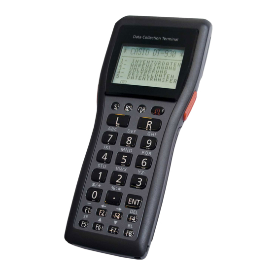
- Page 1 SERVICE MANUAL HANDHELD TERMINAL DT-930 / DT-940 (PY-050) MAY. 2006 DT-930 Ver.3 : Dec. 2011 INDEX...
-
Page 2: Table Of Contents
CONTENTS Page 1. GENERAL ........................ 1 2. FUNCTION AND BASIC OPERATION ..............6 3. DISASSEMBLY/ASSEMBLY ................. 11 4. DIAGNOSTIC PROGRAM ..................23 5. BAR CODE CALIBRATION SETTING ..............6. TECHNICAL INFORMATION ................. 7. EXPLODED VIEW ....................8. PARTS LIST ......................APPENDIX HA-E60IO (EXPLODED VIEW) ............ -
Page 3: General
1. GENERAL 1.1 LINE UP Features Model Name Memory Bluetooth Reader Port Released DT-930M50E 4 MB 16 MB Down-facing reader port May/2006 DT-930M51E 4 MB 16 MB Forward-facing reader port May/2006 DT-930M50NBE 4 MB 16 MB Down-facing reader port May/2006 Í... - Page 4 DT-969CHGE Cradle type Battery Charger For repair: AC Adaptor: DT-9020ADP-GS/DT-9020ADP-US Charge time: Approx. 6 hours DT-923LIB Lithium-ion Battery Pack Rated Capacitance: 540mAh Rated Voltage: 3.6V AD-S15050AE AC Adaptor for Bridge Basic Cradle (HA-E60IO) For repair: Í Input: AC 100-240V, 50-60Hz Output: DC5V, 3.0A DT-9020ADP-GS/DT-9020ADP-US...
- Page 5 Max. 60 mm Reading depth (Max.) DT-930 Forward-facing reader port model: Max. 390 mm DT-930 Down-facing reader port model: Max. 360 mm DT-940: Reading depth (Min.): Max. 50 mm Reading depth (Max.): Max. 350 mm Ambient light: Sunlight: 80,000 Lux or less...
- Page 6 Approx. 69.0 (W) x 173 (D) x 31.6 (H) (DT-930 Forward-facing reader port model) Approx. 69.0 (W) x 180 (D) x 40.2 (H) (DT-930 Down-facing reader port model) Approx. 69.0 (W) x 173 (D) x 31.6 (H) (DT-940) Weight: Approx. 210 g (DT-930 Forward-facing reader port model) Approx.
- Page 7 1.4 PRECAUTIONS The following is the excerpt from a user’s guide. For details, please refer to the user’s guide. 1. Precautions at the time of handling and operating the unit 1-1. On charge, power supply, and a battery 1 Use only DT-923LI/923LIB for charge battery pack. 2 Use only AA (LR6)-size alkaline batteries when using dry batteries.
-
Page 8: Function And Basic Operation
2. FUNCTION AND BASIC OPERATION 2.1 EXPLANATION FOR THE MAIN BATTERY Handheld terminal can be operated by either two AA (LR6)-size alkaline batteries or lithium-ion battery pack (DT-923LIB) as main battery. 2.1.1 BATTERY COVER Be sure to slide the main battery compartment cover lock to the LOCK position. The power does not turn on if the batteries are not properly loaded. - Page 9 2. Load two new AA (LR6)-size alkaline batteries into the main battery compartment, making sure that they face the directions shown in the figure. 3. Attach the battery compartment cover to the Handheld Terminal and slide the main battery compartment cover lock to the LOCK position.
- Page 10 2.4 LOADING AND REMOVING THE BACKUP LITHIUM BATTERY When the backup lithium battery low voltage message appears on the LCD screen, immediately replace the backup battery (lithium). Use a CR2032 lithium battery as the replacement battery. Be sure to turn the Handheld Terminal OFF before you do this.
- Page 11 REMOVING THE BACKUP LITHIUM BATTERY 1. Open the backup battery cover and use a ballpoint pen or other sharp object to remove the backup battery (lithium battery). 2. Close the backup battery cover and tighten the screws. 2.5 RESET OPERATION It is the operation done when the unit doesn’t work normally due to an operational error and other malfunctions.
- Page 12 2.6 POWER ON BY SPECIAL KEY OPERATION Ordinary, the unit starts up with the status of the last operation at the time of power off. (Resume function) Turning the power on with pressing particular key executes particular operation. 2.6.1 SYSTEM MENU START-UP Turning the power on with pressing S and .
-
Page 13: Disassembly/Assembly
Failure to follow the procedures may damage the connectors or other parts. Removable Main Parts Start SUB-BATTERY-COVER BATTERY-COVER (1) Open L-CASE. LASER-HOLDER MIRROR LASER-BASE LASER-MODULE * Down-facing reader * DT-940 only port model only SUB-ASSY IO-ASSY BUZZER LF-HOLDER VIBRATION-MOTOR LASER-FILTER * DT-940 only (2) Remove I-CASE. MAIN-BOARD... - Page 14 3.2 SCREW TYPES A Screw (Y) Silver B Screw (+) Silver C Screw (+) Silver D Screw (+) Silver E Screw (+) Black For OUTER-CASE Flat-head For LASER-MODULE For NOSE-CAP 3.3 DISASSEMBLY PROCEDURES 3.3.1 OPENING AND CLOSING OF L-CASE Procedures (1) Remove BATTERY-COVER and remove the main batteries or rechargeable batteries.
- Page 15 3.3.2 LASER-MODULE AND MIRROR DISASSEMBLY/ASSEMBLY (DT-930) Procedures (1) Remove four C screws (+, silver). (2) Remove LS-SHUT. (3) Hold up LASER-HOLDER and disconnect FFC-CABLE from the connector (single point). (4) Remove LASER-HOLDER. (5) Remove three D screws (+, silver). (6) Remove LASER-MODULE and disconnect FFC-CABLE. (7) Remove MIRROR from LASER-HOLDER.
- Page 16 3.3.3 LASER-MODULE DISASSEMBLY/ASSEMBLY (DT-940) Procedures (1) Peel off the Tape, unlock the connector lock, and remove the FPC. (2) Remove three B screws (+, silver). (3) Remove LASER-HOLDER. (4) Remove four B screws (+, silver). (5) Remove LASER-BASE. (6) Unlock the connector lock, and remove the FPC.
- Page 17 3.3.4 IO-ASSY DISASSEMBLY/ASSEMBLY Procedures (1) Peel a fastening tape for CONNECTOR A and disconnect FFC-CABLE from the connector. (2) Peel a fastening tape for CONNECTOR B and disconnect FFC-CABLE from the connector. (3) Remove two C screws (+, silver). (4) Detach IO-ASSY. * IO-ASSY is fixed to L-CASE with a W tape.
- Page 18 3.3.5 SUB-ASSY DISASSEMBLY/ASSEMBLY Procedures (1) Remove two C screws (+, silver). (2) Hold up SUB-ASSY and disconnect FFC-CABLE from the connector (single point). (3) Detach SUB-ASSY. * For the assembly, reverse the above order. (2) Disconnect FFC-CABLE from the con- nector (indicated in a circle) positioned under SUB-ASSY after releasing the lock upward.
- Page 19 3.3.7 LF-HOLDER AND LASER-FILTER DISASSEMBLY/ASSEMBLY (DT-940) Procedures (1) Remove two B screws (+, silver). (2) Remove LF-HOLDER-A. (3) Remove LF-HOLDER-B and LASER-FILTER. * LASER-FILTER is fixed to CASE and LF-HOLDER-B with a W tape. (1) B Screws LASER-FILTER LF-HOLDER-B < Note >...
- Page 20 3.3.8 VIBRATION-MOTOR DISASSEMBLY/ASSEMBLY Procedures (1) Hold the vibrating part and remove VIBRATION-MOTOR which is fitted into the case. * For the assembly, reverse the above order. Vib. Part VIBRATION-MOTOR 3.3.9 I-CASE DISASSEMBLY/ASSEMBLY MAIN-BOARD is attached to I-CASE. I-CASE must be removed after disconnecting all the cables from LCD and KEY to MAIN-BOARD.
- Page 21 (3) Disconnect FFC-CABLE and cords from LCD. Disconnect FFC-CABLE and cords from LCD. < Note > (1) Fit the cables from TRIGGER-KEY/R into a cut of the case. (2) Pass the LCD cables through the space between bosses. Do not run the cables over them. (3) Do not run the LCD cables over the ribs of the case.
- Page 22 3.3.10 MAIN-BOARD DISASSEMBLY/ASSEMBLY MAIN-BOARD is attached to I-CASE. I-CASE must be removed after disconnecting all the cables from LCD and KEY to MAIN-BOARD. Procedures (1) Remove two C screws (+, silver) on the CPU side. (2) Detach KEY-HOLDER. (3) Remove three B screws (+, silver) on the CPU side. (4) Separate MAIN-BOARD from I-CASE.
- Page 23 3.3.11 LCD DISASSEMBLY/ASSEMBLY Procedures (1) Remove two B screws (+, silver). (2) Detach LCD. * For the assembly, reverse the above order. (2) Hold up and detach LCD after removing two B screws (1). (1) B Screw (1) B Screw 3.3.12 TRIGGER-KEY DISASSEMBLY/ASSEMBLY Procedures (1) Remove TRIGGER-HOLDER on both sides of the case by pulling it upward, using the hook.
- Page 24 < Note > Left and right TRIGGER-KEYS are not identical. The “R” side is up. “R” “L” There are three types of TRIGGER-KEY’s. They are KEY with die stamped “L” on the inner side, that with die stamped “R” on the inner side, and that with no die stamp.
-
Page 25: Diagnostic Program
The document is processed based on Version 2.98. Be sure to update the firmware after replacing the Laser Module (MDL-1001) of DT-940 with a new one. For more information about DT-940 laser test, refer to “4.10 DT-940 LASER SCANNER CHECK”. - Page 26 4.1.3 CHANGE SYSTEM LANGUAGE FROM JAPANESE TO ENGLISH Display Operation Remarks/Result Input [2] button. システムメニュー 1 : AP キドウ 2 : モードセット 3 : ヒヅケ / ジコク セット 4 : テンソウ 5 : バージョン Input [2] button. モ-ドセット 1 : カンキョウ 2 : ヒョウジモード...
- Page 27 4.2 HOW TO START UP THE PROGRAM Press [9] and then press RESET button with keep pressing [9]. Main menu of Diagnostic Program is displayed. Five items are displayed on one screen. C h e c Program1 Ver. 2.98 1. RAM [R] : display next page 2.
- Page 28 Write/Read of Main RAM FROM Write/Read of FROM Liquid Crystal Display IrDA Infrared Light I/F Ls_Scan Laser Scanner For more information about DT-940, refer to “4.10 DT-940 LASER SCANNER CHECK (P47)”. Matrix Key input TRG/MF Trigger key/L and R key ONKEY...
- Page 29 4.7 DIAGNOSTIC PROGRAM Program No.1 Program Name: RAM Display/Read indicator Operation Remarks/Result Press [1] and [ENT] keys in order The program confirms if RAM is < R A M > with Main Menu displays. normally accessible by writing 1 6 M b i t / 6 4 M b i t increment data on RAM and read 9 0 2 0 E 0 0 h 9 1 F F F 8 0 h...
- Page 30 Program No.2 Program Name: FROM Display/Read indicator Operation Remarks/Result Press [2] and [ENT] keys in order The program confirms if FROM is < F R O M > with Main Menu displays. normally accessible by performing C h e c k i n g . . . erase, write, read, and verify on the program.
- Page 31 Program No.3 Program Name: LCD Display/Read indicator Operation Remarks/Result Press [3] and [ENT] keys in order The program confirms if there is no with Main Menu displays. defect on display by showing test pattern on LCD. Black display on full-screen Press [ENT] key.
- Page 32 Program No.4 Program Name: IrDA Display/Read indicator Operation Remarks/Result Press [4] and [ENT] keys in order The program executes Infrared < I r D A > with Main Menu displays. Light I/F operation check 1 . S I R S e n d 2 .
- Page 33 20 sec. an error on the left Sub1 :00000000 occurs. Sub2 :00000000 Please start it again. Sub3 :00000000 Sub4 :00000000 C L R : E x i t Note: If this check is done for DT-940, "Error :2307" will be displayed. ― 31 ―...
- Page 34 Program No.6 Program Name: Matrix Display/Read indicator Operation Remarks/Result Press [6] and [ENT] keys in order The program checks matrix key < M a t r i x k e y > with Main Menu displays. input operation. Caution: Do not press power supply key, otherwise power supply goes off.
- Page 35 Program No.7 Program Name: TRG/MF Display/Read indicator Operation Remarks/Result Press [7] and [ENT] keys in order The program checks trigger keys < T R G k e y > with Main Menu displays. (L, R) and multifunction keys (L, R) T R G input operation.
- Page 36 Program No.8 Program Name: ONKEY Display/Read indicator Operation Remarks/Result Press [8] and [ENT] keys in order The program checks power supply < O N / O F F k e y > with Main Menu displays. key input operation. C L R : E x i t Keep pressing Power Supply Key.
- Page 37 Program No.9 Program Name: BSW Display/Read indicator Operation Remarks/Result Press [9] and [ENT] keys in order The program checks Battery Cover < M B C > with Main Menu displays. Switch on/off operation. C L R : E x i t Open Battery Cover.
- Page 38 Program No.10 Program Name: INIT Display/Read indicator Operation Remarks/Result Press [1], [0] and [ENT] keys in The program confirms Power On < I N I T > order with Main Menu displays. detective operation. I N I T C L R : E x i t Performing RESET operation with <...
- Page 39 Program No. F1 Program Name: Contrast Display/Read indicator Operation Remarks/Result Pressing [F1] key starts up the 32 steps of Contrast adjustments < < C o n t r a s t > > contrast adjustment program while is possible. 2 : U P Menu is displayed.
- Page 40 Program No. F2 Program Name: Backlight Display/Read indicator Operation Remarks/Result Pressing [F2] changes the states Confirm if the backlight turns on C h e c k Program1 of the backlight. properly. There are three states: Ver.2. 98 1.RAM OFF g light slightly up g light up 2.FROM Backlight OFF intensely Confirm if they changes.
- Page 41 Program No. F3, F4, • Program Name: Indicator (Red LED, Green LED, Blue LED) Display/Read indicator Operation Remarks/Result < Red Light > The program confirm if the indicator indicator light up red. Pressing [F3] indicator turns on and off with red light. <...
- Page 42 Program No. 23 Program Name: Vibrator Display/Read indicator Operation Remarks/Result Press [2], [3] and [ENT] keys in The program confirms On and Off < Vibrator > order with Main Menu displays. of vibrator operation. 1 . M o t o r ( A u t o ) 2 .
- Page 43 4.8 ERROR CODE LIST Program Program Nature of error Error Sub 1 Sub 2 Sub 3 Sub 4 Name Data verify error 0100 Address Read data Write data Write data FROM Erase error Red LED lights Write error Program stops Data verify error ―...
- Page 44 4.9 BLUETOOTH CHECK Bluetooth diagnosis is executed with installing another software. DT-930’s/DT-940’s are used for diagnosis. One DT-930/DT-940 (properly operating product) starts up by server mode and another machine for being tested starts up by line mode. The diagnosis is to confirm the...
- Page 45 4.9.3 OPERATING PROCEDURE < Start up the server machine > (1) Execute AP starting up from System Menu and start up the program for BT diagnosis. (2) Input [1]. No ENT needed. B T T e s t V e r 1 . 1 .
- Page 46 < Start up the Line machine > (1) Execute AP starting up from System Menu and start up program for BT diagnosis. (2) Input [1]. No ENT needed. B T T e s t V e r 1 . 1 . B T T r a n 2 .
- Page 47 < Display while connecting > B T T e s t V e r 1 . B T T e s t V e r 1 . L i n e A : C S R b c 2 S e r v e r A : P Y 5 B T - A C o n n 0 0 0 0 N>I>C C o n n 0 0 0 0 N>D>C Itim:XX...
- Page 48 < Display at the sending and receiving completion > B T T e s t V e r 1 . B T T e s t V e r 1 . L i n e A : C S R b c 2 S e r v e r A : P Y 5 0 B T - A C o n n 0 0 0 0 N>I>C C o n n 0 0 0 0 N>D>C...
- Page 49 4.10.1 NECESSARY FILES In order to execute the diagnosis, all the below files have to be transferred to DT-940 Flash ROM (B drive). It is done by using LMWIN or “DUPLICATE HT” in the System menu. These files are contained in the “Dt930\Dt940_Laser_Check” folder.
-
Page 50: Bar Code Calibration Setting
5. BAR CODE CALIBRATION SETTING 5.1 ABOUT THE CALIBRATION SETTING Since DT-930/DT-940 employs swing angle controlling, it is necessary to set bar code calibration (criterion of swing angle setting). The setting has already done in the factory. Perform the setting only when LASER ASSY or MAIN PCB is replaced. - Page 51 CALIBRATION SETTING BAR CODE Guideline Laser beam 5 Releasing the key completes the setting. O B R C A L I B R AT I O N Confirm that the setting is completed correctly. F I N I S H E D . * C O M P L E T E T R G : R E T R Y C L R : E X I T...
- Page 52 6 Press CLR key once to start swing angle controlling. O B R S W I N G C H E C K Green LED turns off. W I D T H E N T : E X I T 7 Check the laser beam position on the bar code (3 steps).
-
Page 53: Technical Information
Combination of the MAIN-PCB and the IO-FPC differs depending on models and types as shown below. When replacing the part, use the correct one to meet the combination of these parts. When replacing the part, refer to the notes indicated in Part List section. DT-930 DT-940 Initial type VA type MAIN-PCB... - Page 54 Notes on DT-930 To distinguish the new VA type from the initial type by viewing the revision label, draw a black dot over [R] of the [R/H] in the revision label. 6.2 MAIN PCB CONNECTOR INFORMATION < PY050-MAINH-ASSY/PY050D1-MAIN-ASSY > < PY050D2-MAIN-ASSY > to IO ASSY to IO ASSY CN501...
- Page 55 6.3 SYSTEM DIAGRAM SH7020 PROM/ 16bit Integrated User Break RAM 1KB Serial I/F 1 Serial I/F 2 Mask ROM Timer Pulse Unit Controller Bus State Interrupt Watch Dog Programable Controller Controller Controller Timer Timing Pttern Controller Bank Input PBXX Swich Signal PBXX PBXX...
-
Page 56: Exploded View
7. EXPLODED VIEW 7.1 FINAL ASSY DT-930 DT-940 DT-930 Down-facing reader port model Forward-facing reader port model UPPER CASE ASSY INNER CASE ASSY COMMON PARTS LOWER CASE ASSY ― 54 ―... -
Page 57: Upper Case Assy
7.2 UPPER CASE ASSY Down-facing reader port model Forward-facing reader port model 8-10 8-10 ― 55 ―... -
Page 58: Lower Case Assy
7.3 LOWER CASE ASSY 14-8 14-18 14-5 14-2 14-6 14-17 14-16 14-7 14-4 14-3 DT-940 14-15 14-14 14-13 14-9 14-1 DT-930 DT-930 Down-facing reader port model Forward-facing reader port model 14-10 14-11 14-12 ― 56 ―... -
Page 59: Inner Case Assy
7.4 INNER CASE ASSY DT-940 20-5 DT-930 20-2 Forward-facing reader port model 20-1 20-3 20-4 DT-930 Down-facing reader port model ― 57 ―... - Page 60 7.5 LABELS AND BUNDLED ITEMS 39 LABEL/CAUTION 37 LABEL/RATING 38 LABEL/REVISION 40 LABEL/REVISION 41 STRAP 54 DESKTOP GUIDE/R 52 WALL MOUNT GUIDE/R 53 DESKTOP GUIDE/L 51 WALL MOUNT GUIDE/L ― 58 ―...
-
Page 61: Parts List
For example, do not use the IO ASSY that belongs to the parts group l for the parts group n. MARKS: R: Rank A: Essential B: Stock recommended C: Less recommended X: No stock recommended Refer the latest “Parts Price Code” at “PARTS FINDER” on the Casio Service WEB site (https:// www.servicecasio.com). ― 59 ―... - Page 62 1 DT-930M51E 4 DT-930M50NBE 7 DT-930M50E-CN 10 DT-930M50NBE-CN 2 DT-930M50E 5 DT-930M50G 8 DT-930M50E-2-CN 11 DT-940M51E-CN 3 DT-930M51NBE 6 DT-930M51E-CN 9 DT-930M51NBE-CN 12 DT-940M51NBE-CN Q'ty Item Code No. Part Name Descriptions 3 4 5 6 7 8 9 10 11 12 FINAL ASSY 10258141 COVER/MAIN BATT...
- Page 63 1 DT-930M51E 4 DT-930M50NBE 7 DT-930M50E-CN 10 DT-930M50NBE-CN 2 DT-930M50E 5 DT-930M50G 8 DT-930M50E-2-CN 11 DT-940M51E-CN 3 DT-930M51NBE 6 DT-930M51E-CN 9 DT-930M51NBE-CN 12 DT-940M51NBE-CN Q'ty Item Code No. Part Name Descriptions 3 4 5 6 7 8 9 10 11 12 LOWER CASE BLOCK 10251577 CASE ASSY/LOWER RJC503130*001V01HK...
- Page 64 1 DT-930M51E 4 DT-930M50NBE 7 DT-930M50E-CN 10 DT-930M50NBE-CN 2 DT-930M50E 5 DT-930M50G 8 DT-930M50E-2-CN 11 DT-940M51E-CN 3 DT-930M51NBE 6 DT-930M51E-CN 9 DT-930M51NBE-CN 12 DT-940M51NBE-CN Q'ty Item Code No. Part Name Descriptions 3 4 5 6 7 8 9 10 11 12 INNER CASE BLOCK 10251583 PCB ASSY/MAIN RJC503131*001V01HK...
-
Page 65: Labels
1 DT-930M51E 4 DT-930M50NBE 7 DT-930M50E-CN 10 DT-930M50NBE-CN 2 DT-930M50E 5 DT-930M50G 8 DT-930M50E-2-CN 11 DT-940M51E-CN 3 DT-930M51NBE 6 DT-930M51E-CN 9 DT-930M51NBE-CN 12 DT-940M51NBE-CN Q'ty Item Code No. Part Name Descriptions 3 4 5 6 7 8 9 10 11 12 LABELS 10394454 LABEL/RATING M51E... -
Page 66: Appendix Ha-E60Io (Exploded View)
APPENDIX. HA-E60IO (EXPLODED VIEW) ― 64 ―... -
Page 67: Ha-E60Io (Parts List)
APPENDIX. HA-E60IO (PARTS LIST) Item Code No. Part Name Description Q'ty 10242985 CASE/UPPER RJC502703-001V01 10242987 PANEL/LED RJC500711-006V01 10242989 PDT GUARD RJC502731-001V01 10242991 BLIND/UPPER RJC502768-001V01 10102278 SCREW/BIND TAP S-BDB0-2X6NI 10242995 HOLDER/PDT RJC502712-001V01 10120352 FILTER/IR RJC501082-001V01 10102323 LENS/LED RJC500723-001V01 10102324 W-TAPE/LED RJC500726-001V01 10102329 BUTTON/DETECT RJC500720-001V01... - Page 68 Ver.1 : Mar. 2007 • Added the OPTION HA-E90BP Bumper (P2) Ver.2 : Jun. 2011 • Addition of New models: DT-930M51NBE, DT-930M50NBE, DT-930M50G, DT-930M51E-CN, DT-930M50E-CN, DT-930M50E-2-CN, DT-930M51NBE-CN, DT-930M50NBE-CN, DT-940M51E-CN, DT-940M51NBE-CN • Addition of the “6.1 Parts Change History” (P48 and P49) Ver.3 : Dec. 2011 • Correction of the 4. DIAGNOSTIC PROGRAM (P41 to P46) • Addition of the “4-1. UPDATING DT-940 FIRMWARE” (P23 to P24) • Addition of the “4.10 DT-940 LASER SCANNER CHECK” (P47) CASIO COMPUTER CO.,LTD. Overseas Service Division 6-2, Hon-machi 1-Chome Shibuya-ku, Tokyo 151-8543, Japan...