
Related Manuals for Casio DT-930


Summary of Contents for Casio DT-930
- Page 1 DT-930 Hardware Manual (Version 1.00) CASIO Computer Co., Ltd. Copyright ©2006. All rights reserved. May 2006...
-
Page 2: Table Of Contents
Table of Contents Chapter 1. Product Overview Chapter 2. External Views 2.1. DT-930M51E 2.2. DT-930M50E 2.3. DT-964IOE Satellite Cradle 2.4. DT-923LIB Battery Pack Chapter 3. System Configuration 3.1. Available Models 3.2. Accessories 3.3. Consumable Items 3.4. Options Chapter 4. General Specifications 4.1. - Page 3 CASIO Computer Co., Ltd. in Tokyo Japan. Information in this document is subject to change without advance notice. CASIO Computer Co., Ltd. makes no representations or warranties with respect to the contents or use of this manual and specifically disclaims any express or implied warranties of merchantability or fitness for any particular purpose.
- Page 4 Editorial Record Manual Version Date edited Page Content 1.00 May 2006 Original version...
-
Page 5: Chapter 1. Product Overview
Applications developed for existing the CASIO DT-900 series handheld terminal widely known as the prominent model amongst logistics and distribution business can be ported into the new DT-930 series. The new series has been designed and developed for software compatibility with the DT-900 series in mind. -
Page 6: Chapter 2. External Views
2. External Views 2.1. DT-930M51E Fig. 2.1 2.2. DT-930M50E Fig. 2.2... -
Page 7: Dt-964Ioe Satellite Cradle
2.3. DT-964IOE Satellite Cradle Fig. 2.3 2.4. DT-923LIB Battery Pack Fig. 2.4... -
Page 8: Chapter 3. System Configuration
3. System Configuration 3.1. Available Models Table 3.1 Model No. Reader Port DT-930M50E Angle shape (downward at 60º) DT-930M51E Straight shape 3.2. Accessories Table 3.2 Item Quantity AA-size (LR6) alkaline battery 2 pcs Wrist strap 1 pc Desktop guides L and R 1 set Wall mount guides L and R 1 set... -
Page 9: Options
3.4. Options Table 3.4 List of the options Model No. Product Specification DT-964IOE Satellite Cradle DT-960IOE Basic Cradle HA-E60IO Bridge Basic Cradle DT-969CHGE Cradle-type Battery Charger DT-923LIB Battery pack Lithium-ion battery pack DT-9020ADP-GS AC adaptor Input 230VAC For DT-960IOE and DT-969CHGE DT-9020ADP-US AC adaptor Input 120VAC For DT-960IOE and DT-969CHGE... -
Page 10: Chapter 4. General Specifications
4. General Specifications 4.1. Hardware Table 4.1 DT-930 hardware specifications Block Item Specification Remark CPU and memory SH1 (32-bit RISC type) Clock frequency 4.92/2.46/1.23 MHz 4 Mbytes F-ROM 16 Mbytes Clock Clock Year/month/day/hour/minute/ with auto self-start Calendar second/day of the week/leap year... - Page 11 EAN, UPCA, UPCE, NW7, ITF, MSI, Industrial 2of5, CODE39, CODE93, CODE128, EAN128, IATA LED for confirmation In green color Communication IrDA Communication mode IrDA Ver. 1.1 compatible and Casio original infrared communication Synchronization Async, Frame Protocol Half-duplex Baud rate (bps) 2400/9600/19200/38400/57600/11 5200/4M Bluetooth Standard Bluetooth Specification Ver.1.2...
-
Page 12: Key Layout
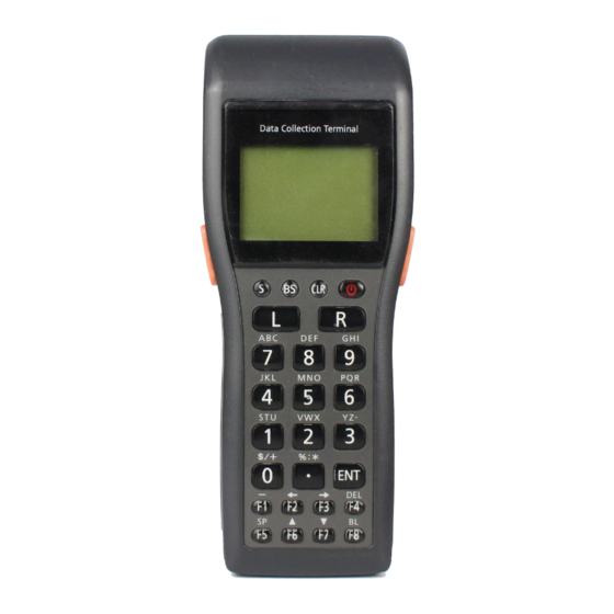
4.2. Key Layout The following illustration shows the keyboard viewed from the front on the terminal. Two trigger keys are located on the left and right sides. L R 9 7 8 4 5 6 1 2 3 $/+ %:* 0... -
Page 13: Compliance
4.3. Compliance Table 4.2 List of the applicable compliance standards Standard Remark EN55022:1998+A1:2000+A2:2003 FCC Part 15 Subpart B EN55024:1998+A1:2001+A2:2003 compatible Safety EN60950-1 UL60950 compatible Bluetooth type approval EN300.328-1/EN300.328-2 FCC Part 15 Subpart EN301.489-1/EN300.489-17 C/RSS-210 compatible Laser EN60825 FDA compatible 4.4. Electrical Table 4.3 Item... -
Page 14: Reliability
4.7. Reliability Table 4.6 Item Specification Remark MTBF of electronic parts 20,000 hours Backlight 5,000 hours Until the brightness of the backlight becomes half-value of the full brightness. Laser scanner 10,000 hours Power switch 300,000 times Trigger key 1,000,000 times Right and Left sides Other keys 300,000 times... -
Page 15: Chapter 5. Cables
5. Cables 5.1. Signal and Wiring • DT-881RSC (Straight) Cradle (9-pin female) side External peripheral (25-pin male) side Signal Signal Case Case Fig. 5.1 • DT-882RSC (Cross) Cradle (9-pin female) side External peripheral (25-pin male) side Signal Signal Case Case Fig. - Page 16 • DT-887AX (Cross) Cradle (9-pin female) side External peripheral (9-pin female) side Signal Signal Case Case Fig. 5.4 • DT-888RSC (Cross for RS-422) Cradle (C-OUT ) side Cradle (C-IN) side Signal Signal ORS+ IRS+ ORS- IRS- OSD+ ISD+ OSD- ISD- IRD+ ORD+ IRD-...
- Page 17 • DT-787AX (Cross) Cradle (14-pin female) side External peripheral (9-pin female) side Signal Signal Case Case Case Fig. 5.8 • DT-788RSC (Cross for RS-485) Signal Signal TRUE (INVERT) INVERT (TRUE) INVERT (TRUE) TRUE (INVERT) Fig. 5.9...
-
Page 18: Chapter 6. Dt-960Ioe Basic Cradle
PC. It has an RS-232C interface for connection to PC and an IR interface using the CASIO original protocol for connection to the terminal. Also, it can supply power to the mounted terminal. -
Page 19: External Views
6.2. External Views RS-232C connector RS-485 connector AC adaptor jack EIAJ TYPE3 Power switch indicator DIP switch DT-930 detection switch Power supply terminal Wall-mounting unit Rating lable Fig. 6.1 Note: If this page is not printed properly, change the printer graphic property from "Vector Graphic" to... -
Page 20: Dimensions And Weight
6.3. Dimensions and Weight Table 6.1 Dimensions and weight Item Specification Desk top configuration 110 (W) mm x 220 (D) mm x 100 (H) mm Wall mounting configuration 110 (W) mm x 220 (D) mm x 110 (H) mm Weight Approx. -
Page 21: Hardware Specifications
I/F level Mark : LED off Pulse width of ON is Space: LED on (pulse width 1.6 usec.approx) fixed irrespective communicati on speed. Usage Connecting DT-930 I/F to Protocol RS-232C Host PC Synchronization Start/Stop bit Method Half duplex Data format... - Page 22 (Power LED) While Green in flashing 2-color LED communicating (green is used) SD Power Input voltage DC 9.5V±5% supply Current consumption 300 mA (max.) when supplying power to DT-930 Applicable plug type EIAJ RC5320 type 3 Center pin : Continue.
-
Page 23: Electric
AC adaptor Input AC230V DT-9020ADP-G Input AC120V DT-9020ADP-U Power Output voltage 5V±10% supply Output current 300mA block Excess current Drop-type excess current protection circuit (600mA Protection or more) Terminal Layoutf of block terminals Power supply XIRCNT Not used 6.5. Electric Table 6.3 Item Specification... -
Page 24: Environment
6.6. Environment Table 6.4 Item Specification Remark Temperature Operation 0 ºC to 40 ºC Storage -10 ºC to 50 ºC Humidity Operation 30% to 80%RH At 40ºC. No condensation Storage 30% to 90%RH Electrostatic Malfunction at 5 KV Conditions: Equivalent human body resistance: 100 ohm Destruction at 10 KV Equivalent human body capacity: 250 pF Frequency of application : 10 times... -
Page 25: Compliance
Safety EN60950 Applicable to DT-9020ADP-G and DT-9020ADP-U. 6.10. Chain Connection 6.10.1. Configurations and Operating Conditions Basic Cradle and Host P/C (with external device connected) DT-930 RS-232C Basic Cradle 115.2 Kbps (max.) HOST PC IR communication 115.2 Kbps (max.) Fig. - Page 26 Basic Cradles and Host P/C HOST PC DT-930 DT-930 DT-930 RS-232C cable Basic Cradle Basic Cradle Basic Cradle 115 Kbps (max.) RS-485 RS-485 Modular cable Modular cable RS-232C connct. IR comm. IR coom. IR comm. 115 Kbps (max.) 115 Kbps (max.) 115 Kbps (max.)
- Page 27 Multiple Basic Cradles DT-930 DT-930 DT-930 Basic Cradle Basic Cradle Basic Cradle RS-485 RS-485 Modular cable Modular cable IR comm. IR comm. IR comm. 115Kbps (max.) 115Kbps (max.) 115Kbps (max.) Termination At middle Termination Fig. 6.4 DIP Switch Setting Table 6.10...
-
Page 28: 6.10.2. Cable Specifications
6.10.2. Cable Specifications Cable for Chain Connection (short distance) A cable for the chain connection within distance of 1 meter or less (between DT-960IOE and DT-960IOE) is available as option. The model number of the cable is DT-788RSC (cable length: 1 View from side Max. - Page 29 Cable for Chain Connection (long distance) View from side Max. 1,000 m View from above 1 2 3 4 5 6 1 2 3 4 5 6 Cable Modular plug SK-UTP 100M3P 6/6-6FR SYK Fig. 6.7 Wiring of the cable (cross and twist pair) Cradle at downstream side Cradle at upper stream side Pin no.
-
Page 30: 6.10.3. Notes About Chain Connection
Precautions to be observed when manufacturing cables • If the CASIO cables cannot be used, and custom-made cables are required instead, use the manufacturer-specified cramping tool to cramp the modular connector and cable. Note that defective cramping may damage communication. -
Page 31: Chapter 7. Dt-964Ioe Satellite Cradle
7. DT-964IOE Satellite Cradle The DT-964IOE Satellite Cradle is a cradle dedicated for DT-930. It facilitates non-contact data transfer between a PC and the terminal, and, if multiple cradles are chain-connected, each cradle facilitates connecting the terminal mounted on the cradle to a single PC. It has an RS-232C interface for connection to PC and an IrDA interface for connection to the terminal. -
Page 32: External Views
7.2. External Views RS-422 connector (C-IN side) RS-232C connector RS-422 connector (C-OUT side) AC adaptor jack EIAJ TYPE4 LED panel DIP switch DT-930 detection switch Charging/ power supply Wall-mounting unit terminal Lithium-Ion battery pack charging compartment Rating label Fig. 7.1 Note: If this page is not printed properly, change the printer graphic property from "Vector Graphic"... -
Page 33: Dimensions And Weight
7.3. Dimensions and Weight Table 7.1 Dimensions and weight Item Specification Desktop configuration 110 (W) mm x 220 (D) mm x 100 (H) mm Wall mount configuration 110 (W) mm x 220 (D) mm x 110 (H) mm Weight 500 g (approx.) (see notes) Notes: •... -
Page 34: Hardware Specifications
I/F level Mark : LED off On-pulse width Space: LED on (pulse width 1.6 usec. approx.) is fixed irrespective of the ransmission rate. Usage Connecting DT-930 I/F to Protocol RS-232C Host PC Synchronization Start/Stop bit Method Full duplex/Half duplex Data format... - Page 35 Remark Chain Protocol RS-422 Max. length 1 Synchronization Start/Stop bit Same specification as I/F to DT-930. Method Half duplex Data format Data bit : 8 Fixed Stop bit : 1 Parity bit : none Baud rate (bps) 9600, 38.4K, 115.2K...
- Page 36 Power switch Seesaw switch Terminal detection switch Push switch Indicatio READY/POW DT-930 is being mounted. 2-color LED Power LED DT-930 is not being mounted. Green CHG1 While charging 2-color LED Charging is complete. Green (green is used) CHG1 LED Charging ends abnormally.
-
Page 37: Electric
Power Charging Voltage to check 2.6V±0.1 V supply module battery anomaly Dark current 4.3 µA Charging time Approx. 5 hours At ambient temperature Power Output voltage DC5V±10% supply Output current 300 mA block Excess current Drop type excess current protection protection circuit (600 mA or greater) Terminal... -
Page 38: Environment
50 times Connection/removing of RS-232C 500 times the respective connectors RS-422 500 times DC jack 500 times Mounting and removing DT-930 power 20,000 times terminal on/from cradle supply/charging terminals Installing and removing Charging spring 5,000 times battery pack in/from the compartment Notes: •... -
Page 39: Compliance
7.9. Compliance Table 7.7 Standard Remark Radio interference EN55022:1994, A2:1997 Class B Tested with AD-S42120AE CISPR Pub.22:1993, A2:1996 Class B Electromagnetic EN50082-1: 1997 Tested with AD-S42120AE compatibility generic immunity Safety EN60950 Applicable only to AD-S42120AE... -
Page 40: Chain Connection
115.2 Kbps (max) Fig. 7.2 DIP Switch Setting Table 7.8 Use of Switch Destination Switch Setting Remark Baud rate DT-930 and To GA/to CPU PB6 IRSPEED0 115.2Kbps switching 0 Cradle Baud rate DT-930 and To GA/to CPU PB7 IRSPEED1 Note 1... - Page 41 Fig. 7.3 DIP Switch Setting Table 7.9 Setting Use of Switch Destination Switch Remark At end middle Baud rate DT-930 and To GA/to CPU PB6 IRSPEED0 115.2Kbps switching 0 Cradle Baud rate DT-930 and To GA/to CPU PB7 IRSPEED1 Note 1...
- Page 42 Multiple Satellite Cradles and Host P/C DT-930 DT-930 DT-930 HOST PC RS-232C Satellite Cradle Satellite Cradle Satellite Cradle 115.2 Kbps (max) RS-422 RS-422 Modular cable Modular cable Active operation Passive operation Passive operation IR comm. IR comm. IR comm. 115.2 Kbps (max) 115.2 Kbps (max)
- Page 43 DIP Switch Setting Table 7.11 Setting Passive Use of Switch Destination Switch Remark Through At end middle Baud rate DT-930 and To GA/to CPU IRSPEED 115.2Kbps switching 0 Cradle Baud rate DT-930 and To GA/to CPU IRSPEED switching 1 Cradle...
-
Page 44: Cable Specifications
7.10.2. Cable Specifications Cable for Short Distance (1 m or less) View from side Max. 1 m View from above 1 2 3 4 5 6 1 2 3 4 5 6 Cable (see Table 11.16) Modular plug 6/6-6 FR SYK Fig. - Page 45 Cable for Chain Connection View from side Max. 1,000 m View from above 1 2 3 4 5 6 1 2 3 4 5 6 Modular plug Cable 6/6-6 FR SYK50 SK-UTP 100M3P Fig. 7.8 Wiring of the cable (straight connection, pin-to-pin) Cradle at downstream side Cradle at upper stream side Pin no.
-
Page 46: Precautions
Precaution to be observed when manufacturing cables • If CASIO cables cannot be used, and custom-made cables are required, use the manufacturer- specified cramping tool to cramp the modular connector and cable. Note that defective cramping may damage communication. -
Page 47: Chapter 8. Ha-E60Io Bridge Basic Cradle
8. HA-E60IO Bridge Basic Cradle The HA-E60IO Bridge Basic Cradle is a cradle dedicated for DT-930. It facilitates non-contact data transfer between PC and the terminal. Also, it can supply power to the mounted terminal. 8.1. Features at a Glance •... -
Page 48: External Views
8.2. External Views Fig. 8.1 Note: If this page is not printed properly, change the printer graphic property from "Vector Graphic" to "Raster Graphic". -
Page 49: Dimensions And Weight
Hardware Specifications Table 8.2 Block Item Specification Remark I/F to Protocol Original Ir Interface (IrDA device) DT-930 Conforms to Version 1.1 Synchronizatio Asynchronous, Frame synchronous Method Half duplex Baud rate (bps) 4Mbps ( MAX ) I/F to Protocol USB Ver. 1.1 conformity... -
Page 50: Electric
8.5. Electric Table 8.3 Item Specification Remark Power consumption 1.0 A With applicable AC adaptor Available power supply AD-S15050A DC 5V±5% Line noise strength Malfunction at 1000V Pulse frequency : 5KHz Burst cycle : 300 milliseconds No. of pulses : 75 Burst term : 15 milliseconds Instantaneous power line off Malfunction after 10... -
Page 51: Compliance
8.9. Compliance Table 8.7 Standard Remark EN55022:1998+A1:2000+A2:2003 Class B EN55024:1998+A1:2001+A2:2003 EN61000-3-2:2000 EN61000-3-3:1995+A1:2001... -
Page 52: Chapter 9. Dt-969Chge Cradle-Type Battery Charger
Features at a Glance • Charging battery pack and supplying power to DT-930. It has integrated charge circuit to charge the battery pack and to supply power preventing battery’s power being consumed by the terminal. A period of approximately five hours is required to fully charge the battery pack. -
Page 53: External Views
9.2. External Views AC adaptor jack EIAJ Type 3 LED panel DT-930 detection switch Charging/po wer supply Wall-mounting unit terminal Lithium-Ion battery pack charging compartment Rating label Fig. 9.1 Note: If this page is not printed properly, change the printer graphic property from "Vector Graphic" to... -
Page 54: Dimensions And Weight
If the hook and cover for wall mounting are used, the product weight is increased by approximately 10 g. • If the nose guide for straight opening is used, the product weight is increased by approximately 5 g. 9.4. Circuit Block Diagram Charge Module DT-930 HTON HTSW AC adaptor Power Management HTADP Fig. 9.2... -
Page 55: Hardware Specifications
When charging is complete. Green CHG1 LED Charging ends abnormally CHG2 While charging 2-color LED (while Wait for charging charging the battery in DT-930) CHG2 LED When charging is complete. Green Charging ends abnormally Power Input voltage DC9.5V±5% block Power consumption current 600 mA (max.) (25 mA when not... -
Page 56: Electric
9.6. Electric Table 9.4 Item Specification Remark Power consumption 5.7 W With applicable AC adaptor Available power supply DC 9.5V±5% With EIAJ RC5320 type 3 plug DT-9020ADP-G Input: AC 220 to 240V, 50/60 Hz Input conditions: Voltage: ±10% of rated input voltage DT-9020ADP-U Input: AC 100 to 120V, 50/60 Hz Frequency: ±1 Hz of rated input... -
Page 57: Reliability
Power switch 3,000 times Terminal detection switch 20,000 times Connecting/disconnecting DC jack 500 times AC adaptor Mounting and removing DT-930 power supply/charging 20,000 times the terminal on/from terminals cradle Installing and removing the battery pack in/from the 5,000 times compartment Notes: •... -
Page 58: Chapter 10. Product Identification And Reference Numbers
10. Product Identification and Reference Numbers On the back of the DT-930 and the dedicated option, there is a bar code and numbers printed on label as shown in the figure. This bar code is represented by 15 digits of Code128 symbology and by alphanumeric characters beneath the bar code.