Makita DHP480 Technical Information
18v cordless hammer driver drill
Hide thumbs
Also See for DHP480:
- Instruction manual (33 pages) ,
- Instruction manual (61 pages) ,
- Instruction manual (73 pages)
Table of Contents
Advertisement
T
ECHNICAL INFORMATION
Models No.
Description
C
ONCEPT AND MAIN APPLICATIONS
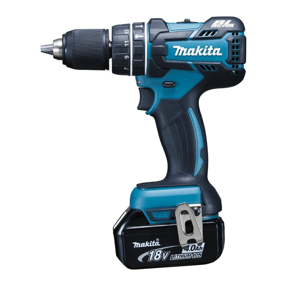
Model DHP480 is a superior class cordless hammer driver drill model, featuring:
• Compact tool size with an overall length of 199mm (7-7/8")
• High power and maintenance-free achieved with new BLDC(BrushLess DC) motor
• Enhanced dust and drip-proof design to ensure reliable operation even under
bad weather.
• Battery fuel gauge shows the remaining capacity by pulling switch trigger.
S
pecification
Voltage: V
Capacity: Ah
Battery
Energy capacity: Wh
Cell
Charging time (approx.): min.
Max output: W
No load speed:
min
¹=rpm
ˉ
Impacts per minute:
min
¹ = ipm
ˉ
Capacity of drill chuck: mm (")
Capacity: mm (")
Torque setting
Clutch torque setting: N.m (in.lbs)
Max lock torque: N.m (in.lbs)
Max fastening
torque: N.m (in.lbs)
Electric brake
Mechanical speed control
Variable speed control
Reversing switch
LED job light
Weight according to
EPTA-Procedure 01/2003: kg (lbs)
S
tandard equipment
Battery*
3
3
Charger*
Battery cover*
4
Plastic carrying case*
Belt clip
+ – bit 2-45
O
ptional accessories
Fast charger DC18RC
Charger DC18SD
Charger DC24SC
Automotive charger DC18SE
DHP480
18V Cordless Hammer driver drill
1.3, 1.5, 2.0, 3.0, 4.0, 5.0
24, 27, 36, 54, 72, 90
15, 15, 24, 22, 36, 45 with DC18RC
High
Low
High
Low
Steel
Wood
Masonry
16 stage + drill mode
Soft joint
Hard joint
3
*3: Battery, charger and Plastic carrying case are not supplied with "Z" model
*4: Supplied with the same quantity of extra Battery
Note: The standard equipment may vary by country or model variation.
Battery BL1815
Battery BL1815N
Battery BL1820
18
Li-ion
370
0 - 1,550
0 - 400
0 - 23,000
0 - 6,000
1.5 (1/16) - 13 (1/2)
13 (1/2)
38 (1-1/2)
13 (1/2)
1.0 - 5.0 (9 - 44)
60 (530)
36 (320)
54 (480)
Yes
Yes (2 speed)
Yes
Yes
Yes
1.5 (3.2)*
1
1.7 (3.8)*
2
Battery BL1830
Battery BL1840
Battery BL1850
for ASC & Sales Shop
L
W
Dimensions: mm (")
Length (L)
Width (W)
Height (H)
*1:
with BL1815, BL1815N or BL1820
*2:
with BL1830, BL1840 or BL1850
Drill bits for wood
Driver bits
Drill bits for steel
Bit holder
Drill bits for masonry
OFFICIAL USE
PRODUCT
P 1/ 12
H
199 (7-7/8)
79 (3-1/8)
243 (9-9/16)*1
260 (10-1/4)*2
Advertisement
Table of Contents

Related Manuals for Makita DHP480


Summary of Contents for Makita DHP480
- Page 1 18V Cordless Hammer driver drill ONCEPT AND MAIN APPLICATIONS Model DHP480 is a superior class cordless hammer driver drill model, featuring: • Compact tool size with an overall length of 199mm (7-7/8") • High power and maintenance-free achieved with new BLDC(BrushLess DC) motor •...
- Page 2 P 2/ 12 epair CAUTION: Repair the machine in accordance with “Instruction manual” or “Safety instructions”. [1] NECESSARY REPAIRING TOOLS Code No. Description Use for Hex bar 10 with square socket removing Drill chuck 1R298 removing Drill chuck 1R359 Chuck removing tool (If it is impossible to remove as per the illustration in Figs.
- Page 3 P 3/ 12 epair [3] DISASSEMBLY/ASSEMBLY [3] -1. Drill chuck (cont.) ASSEMBLING (1) Set Hex wrench 10 to Vise as drawn in Fig. 3. Fig. 3 Correct Wrong Clamp the long end. Clamp flat surfaces Do not clamp edges Do not clamp of Hex wrench 10 of Hex wrench 10.
- Page 4 P 4/ 12 epair [3] DISASSEMBLY/ASSEMBLY [3] -1. Drill chuck (cont.) DISASSEMBLING If it is difficult to remove Drill chuck as drawn in Figs. 1 and 2, use 1R359. (Fig. 6) Fig. 6 Fig. 6B Fig. 6A How to Use 1R359 1) Disassemble Gear assembly until Spindle can be seen.
- Page 5 P 5/ 12 epair [3] DISASSEMBLY/ASSEMBLY [3] -2. Rotor, Gear assembly DISASSEMBLING (1) Remove Drill chuck as drawn in Figs. 1 an 2. (2) Disassemble Gear assembly as drawn in Fig. 8. Fig. 8 1. By unscrewing nine 3x16 tapping screws, 2.
- Page 6 P 6/ 12 epair [3] DISASSEMBLY/ASSEMBLY [3] -2. Rotor, Gear assembly (cont.) Caution for Handling of Rotor When handling or storing multiple Rotors, be sure to keep a proper distance between Rotors as shown in Fig. 9A because Rotor is a strong magnet, failure to follow this instruction could result in: •...
- Page 7 P 7/ 12 epair [3] DISASSEMBLY/ASSEMBLY [3] -2. Rotor, Gear assembly (cont.) ASSEMBLING (3) Assemble Speed change lever assembly as drawn in Fig. 12. Fig. 12 front Compression spring 4 Pin on the lever of Gear assembly 1. Apply the front Compression spring 4 of Speed change lever Drill chuck side...
- Page 8 P 8/ 12 epair [3] DISASSEMBLY/ASSEMBLY [3] -2. Rotor, Gear assembly (cont.) ASSEMBLING (4) Assemble Gear assembly and Rotor section to Housing L as drawn in Fig. 13. Fig. 13 Stator Gear assembly 1. Make sure that the ribs of Housing L are fitted tightly in the notches of Stator.
- Page 9 P 9/ 12 ircuit diagram Fig. D-1 Color index of lead wires' sheath Black Orange White Blue Yellow Switch Printed Connector Stator wiring board Connector Terminal Controller Terminal iring diagram Fig. D-2 Wiring to Switch Flag connectors of Lead wires must be connected to Switch so that their wires come to Housing L side.
- Page 10 P 10/ 12 iring diagram Fig. D-3 Wiring in upper space of Switch Put connector Rib A Rib B Rib C to this space. LED light circuit Rib D Put the slack portion of Lead wires Put the slack portion of Lead wires of Stator and those of Controller for connecting to LED light circuit of Printed wiring board to the space...
- Page 11 P 11/ 12 rouble shooting Whenever you find any trouble in your machine, first, refer to this list to check the machine for solution. Note in Repairing Fig. T-1 (1) Use the full charged battery which has the star mark. (Fig. T-1) (2) When Housing is disassembled, check the conditions of the electrical parts Star mark (Connectors, Lead wires, Switches, etc.), Armature, Stator, Gear section, etc.
- Page 12 P 12/ 12 rouble shooting Test for recognizing the trouble on Controller (1) Set Digital tester (1R402) to the diode mode. (2) Attach the tester bars as drawn in Figs. T-2 and T-3. Fig. T-2 Fig. T-3 1. Attach Tester bar (black) to the terminal of 1.