Sign In
Upload
Manuals
Brands
Yamaha Manuals
Network Card
ERCX Series
Yamaha ERCX Series Manuals
Manuals and User Guides for Yamaha ERCX Series. We have
3
Yamaha ERCX Series manuals available for free PDF download: User Manual, Supporting Supplement Manual
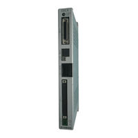
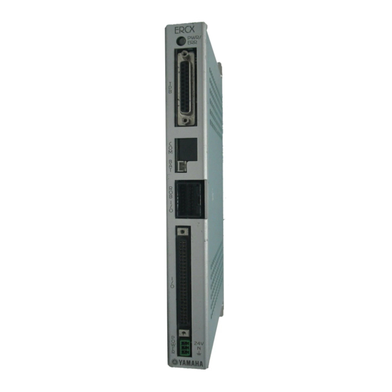
Yamaha ERCX Series User Manual (260 pages)
SINGLE-AXIS ROBOT CONTROLLER
Brand:
Yamaha
| Category:
Controller
| Size: 1.69 MB
Table of Contents
Table of Contents
3
Chapter 1 OVERVIEW
9
Features of the ERCX Series Controller
10
Setting up for Operation
11
External View and Part Names
12
ERCX Controller
12
Tpb
14
System Configuration
15
Accessories and Options
16
Accessories
16
Peripheral Options
16
Chapter 2 INSTALLATION and CONNECTION
17
Installing the ERCX Controller
18
Installation Method
18
Installation Location
18
Connecting the Power Supply
19
Power Supply
19
Connecting the Power Supply
20
Insulation Resistance and Voltage Breakdown Tests
20
Grounding
21
Connecting the ERCX to the Control Unit
21
Connecting to the Robot
22
Robot I/O Connector and Signal Table
22
Connecting to the I/O Connector
23
Connecting the Absolute Battery
24
Chapter 3 I/O INTERFACE
25
I/O Signals
26
Input Signal Description
27
Dedicated Command Input
27
General-Purpose Input (DI0 to DI15)
30
SERVICE Mode Input (SVCE)
31
Interlock (LOCK)
31
Emergency Stop Inputs 1, 2 (EMG1, EMG2)
31
Output Signal Description
32
Dedicated Output
32
General-Purpose Output (DO0 to DO12)
33
I/O Circuits
33
I/O Circuit Specifications
33
I/O Circuit and Connection Example
34
I/O Connection Diagram
36
General Connections
36
Connection to PLC Output Unit
37
Connection to PLC Input Unit
38
I/O Control Timing Charts
39
When Turning the Power on
39
When Executing a Dedicated Input Command
40
When Interlock Signal Is Input
44
When Emergency Stop Is Input
45
When Alarm Is Issued
45
When Executing a Point Movement Command
46
I/O Assignment Change Function
47
Changing the I/O Assignment
47
I/O Signal Descripion
49
Timing Chart
52
Chapter 4 BASIC OPERATION of the TPB
61
Connecting and Disconnecting the TPB
62
Connecting the TPB to the ERCX Controller
62
Disconnecting the TPB from the ERCX Controller
63
Different Points from SRCX and DRCX Controllers
63
Basic Key Operation
64
Reading the Screen
65
Program Execution Screen
65
Program Edit Screen
65
Point Edit Screen (Teaching Playback)
66
DIO Monitor Screen
66
Hierarchical Menu Structure
67
Restricting Key Operation by Access Level
68
Explanation of Access Level
68
Changing an Access Level
69
Chapter 5 PARAMETERS
71
Setting the Parameters
72
Parameter Description
73
Chapter 6 PROGRAMMING
91
Basic Contents
92
Robot Language and Point Data
92
Using the TPB to Enter the Robot Language
92
Program Specifications
92
Editing Programs
94
Creating Programs after Initialization
94
Creating a New Program
96
Adding a Step
97
Correcting a Step
99
Inserting a Step
100
Deleting a Step
101
Program Utility
102
Copying a Program
102
Deleting a Program
103
Viewing the Program Information
104
Chapter 7 EDITING POINT DATA
105
Manual Data Input
106
Teaching Playback
107
Direct Teaching
109
Manual Control of General-Purpose Output
111
Manual Release of Holding Brake
112
Deleting Point Data
113
Tracing Points (Moving to a Registered Data Point)
114
Chapter 8 ROBOT LANGUAGE
115
Robot Language Table
116
Robot Language Syntax Rules
117
Command Statement Format
117
Variables
118
Program Function
119
Multi-Task Function
119
Limitless Movement Function
120
Robot Language Description
122
Mova
122
Movi
122
Movf
123
Jmp
123
Jmpf
124
Jmpb
125
Call
126
Wait
127
Timr
127
Srvo
129
Stop
129
Orgn
130
Ton
131
Toff
131
Jmpp
132
Mat
133
Msel
134
Movm
135
Jmpc
136
Jmpd
136
Csel
137
Shft
140
Sample Programs
141
Moving between Two Points
141
Moving at an Equal Pitch
141
Picking up 3 Kinds of Workpieces Flowing on the Front Conveyor and Placing Them on the Next Conveyors While Sorting
144
Switching the Program from I/O
146
Axis Movement and I/O Multi-Task
148
Limitless Movement at same Pitch
151
Limitless Rotation
152
Chapter 9 OPERATING the ROBOT
153
Performing Return-To-Origin
154
Return-To-Origin by the Search Method
154
Return-To-Origin by the Mark Method
156
Using Step Operation
158
Using Automatic Operation
161
Switching the Execution Program
163
Emergency Stop Function
164
Initiating an Emergency Stop
164
Recovering from an Emergency Stop
164
Displaying the Memory I/O Status
166
Displaying the Variables
167
Chapter 10 OTHER OPERATIONS
169
Initialization
170
DIO Monitor Display
172
Display from the Monitor Menu
172
Display from the DIO Key Operation
173
System Information Display
173
SERVICE Mode Function
174
Safety Settings for SERVICE Mode
175
Enabling/Disabling the SERVICE Mode Function
177
Setting the SERVICE Mode Functions
179
System Utilities
181
Viewing Hidden Parameters
181
Using a Memory Card
182
Saving Controller Data to a Memory Card
182
Loading Data from a Memory Card
184
Formatting a Memory Card
186
Viewing the ID Number for Memory Card Data
187
Duty (Load Factor) Monitor
188
Measuring the Duty (Load Factor)
190
Chapter 11 COMMUNICATION with PC
191
Communication Parameter Specifications
192
Communication Cable Specifications
193
Connecting to the Computer with a 25-Pin D-Sub Connector
193
Connecting to the Computer with a 9-Pin D-Sub Connector
193
Communication Command Specifications
194
Communication Command List
195
Communication Command Description
198
Robot Movements
198
Data Handling
207
Utilities
219
Chapter 12 MESSAGE TABLES
223
Error Messages
224
Error Message Specifications
224
Command Error Message
224
Operation Error Message
225
Program Error Message
226
System Error Message
227
Multi-Task Error Message
227
TPB Error Messages
228
Stop Messages
229
Message Specifications
229
Displaying the Error History
230
Chapter 13 TROUBLESHOOTING
233
If a Trouble Occurs
234
Alarm and Countermeasures
235
Alarm Specifications
235
Alarm Message List
236
Troubleshooting for Specific Symptom
239
Relating to the Robot Movement
239
Relating to the I/O
241
Other
242
Displaying the Alarm History
243
Chapter 14 MAINTENANCE and WARRANTY
245
Warranty
246
Replacing the System Backup Battery
246
Replacing the Absolute Battery
246
Updating the System
247
Chapter 15 SPECIFICATIONS
249
ERCX Sereis
250
Basic Specifications
250
Robot Number List
251
LED Display
251
Absolute Battery Unit
251
Tpb
252
Basic Specifications
252
Chapter 16 APPENDIX
253
Operation When Not Using Absolute Function
254
How to Handle Options
255
Memory Card
255
Handling the I/O Checker
257
POPCOM Communication Cable
258
Advertisement
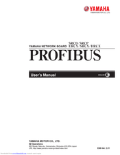
Yamaha ERCX Series User Manual (148 pages)
PROFIBUS NETWORK BOARD
Brand:
Yamaha
| Category:
Network Card
| Size: 0.99 MB
Table of Contents
Table of Contents
5
Cautions to Ensure Safety
7
Basic Safety Points
8
System Design Safety Points
8
Installation and Wiring Safety Points
9
Start-Up and Maintenance Safety Points
10
Precautions When Disposing of the Unit
10
Warranty
10
PROFIBUS Unit
11
PROFIBUS Unit Features
12
PROFIBUS System Concept
13
BROFIBUS Cable Connections
14
Parallel I/O Connector
15
Controller (Slave Station) System Setting
17
Validating the PROFIBUS Unit
17
Setting the Station Address
18
Checking the Communication Speed
19
Sequencer (Master Station) Settings
20
Exchanging Data with the Controller
20
I/O Information
21
Profile (I/O Signal Table)
21
Dedicated Command Inputs
23
General-Purpose Inputs (SI200 - SI231)
27
Interlock (LOCK)
28
Emergency Stop Input (EMG)
28
Service Mode (SVCE)
29
Dedicated Outputs
30
General-Purpose Outputs (SO200 - SO231)
31
Timing Chart
32
Right after Controller Power Turns on
32
Dedicated Input Command Execution
33
When Interlock Signal Is Input
37
When Emergency Stop Signal Is Input
38
When an Alarm Is Issued
39
When Point Movement Commands Are Run
40
I/O Assignment Change Function
41
Changing the I/O Assignment
41
I/O Assignment List
42
I/O Assignment Selection Parameter Description
44
I/O Signal Descripion
46
Timing Chart
51
Robot Language
61
Movf
61
Jmpf
62
Jmpb
63
Wait
64
Emulated Serialization on Parallel DIO
65
Remote Command
67
Remote Command Specifications
67
Remote Command & Status Value List
68
Special Commands
71
Remote Command Details (Robot Operation)
72
Remote Command Details (Data Handling)
106
Remote Command Details (Utilities)
129
Remote Command Details (Special Commands)
133
Status Details
134
Current Position Indication Mode
135
Sending/Receiving Example
136
Other Operations
137
Serial I/O Display
137
Manual Control of General-Purpose Output
140
Error Message
141
Troubleshooting
142
Specifications
144
Supplement
145
GSD Files
145
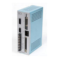
Yamaha ERCX Series Supporting Supplement Manual (34 pages)
ROBOT CONTROLLER
Brand:
Yamaha
| Category:
Controller
| Size: 2.88 MB
Table of Contents
Table of Contents
5
Chapter 1 CE Marking
7
Safety Information
8
CE Marking
9
Safety Precautions During Robot Operation
11
Safety Precautions During Maintenance
11
Precautions for Motor Overload
11
Warning Labels
12
Operating Environment
14
Chapter 2 Configuration and Connection
15
Configuration of CE Marking Controller
16
Connecting the Power Supply
22
Chapter 3 EMC Countermeasures
26
Typical Component Layout for EMC Countermeasures
27
Precautions for Cable Connections
29
Chapter 4 SPECIFICATIONS
30
CE Marking
31
Advertisement
Advertisement
Related Products
Yamaha ERCX
Yamaha ERCX-B1
Yamaha ERG121C
Yamaha Electone EL-70
Yamaha EMS 68S
Yamaha EMS 88S
Yamaha EK15DMH
Yamaha EDL7000SDE
Yamaha EF6300iSDE
Yamaha Sound editor
Yamaha Categories
Motorcycle
Musical Instrument
Electronic Keyboard
Receiver
Amplifier
More Yamaha Manuals
Login
Sign In
OR
Sign in with Facebook
Sign in with Google
Upload manual
Upload from disk
Upload from URL