Sign In
Upload
Manuals
Brands
ABB Manuals
DC Drives
ACS880-04 drive modules
ABB ACS880-04 drive modules Manuals
Manuals and User Guides for ABB ACS880-04 drive modules. We have
17
ABB ACS880-04 drive modules manuals available for free PDF download: Firmware Instructions, Firmware Manual, Hardware Manual, Quick Installation And Start-Up Manual, Quick Installation Manual, Electrical Planning Instructions, Electrical Planning Manual, Quick Installation Instructions, Application Manual, Application Supplement, User Manual, Manual
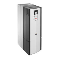
ABB ACS880-04 drive modules Firmware Instructions (664 pages)
single drive
Brand:
ABB
| Category:
Controller
| Size: 11.89 MB
Table of Contents
Table of Contents
5
List of Related Manuals
2
Table of Contents
5
Introduction to the Manual
13
What this Chapter Contains
13
Applicability
13
Licensing
14
Safety Instructions
14
Target Audience
14
Contents of the Manual
15
Related Documents
15
Terms and Abbreviations
16
Cybersecurity Disclaimer
19
Using the Control Panel
21
Control Locations and Operating Modes
23
What this Chapter Contains
23
Local Control Vs. External Control
24
Local Control
24
External Control
25
Operating Modes of the Drive
26
Speed Control Mode
27
Torque Control Mode
27
Frequency Control Mode
27
Special Control Modes
27
Quick Start-Up Guide
29
Contents of this Chapter
29
Before You Start
29
Safety
29
Drive Start-Up
30
ESP Application Minimum Configuration
38
ESP Program Features
41
What this Chapter Contains
41
Overview of ESP Control Program
41
Backspin Supervision
42
Restart Delay
42
Backspin Speed Observer
42
Backspin Speed Observer Constraints
45
Starting the Motor
46
Starting Speed
46
Acceleration Assistance
46
Kick-Start
47
Current Pulse-Start
48
ESP Production Mode
49
Manual Mode
49
Automatic Process Control Mode
50
Underload and Overload Protection
52
Underload Ride through Recovery Sequence
54
Overload Recovery Sequence
56
Motor Voltage Control
58
Pump Impeller Cleaning
59
Pump Curves
60
Program Features
61
What this Chapter Contains
61
Drive Configuration and Programming
62
Programming Via Parameters
62
Adaptive Programming
63
Application Programming
63
Control Interfaces
64
Programmable Analog Inputs
64
Programmable Analog Outputs
64
Programmable Digital Inputs and Outputs
64
Programmable Relay Outputs
65
Programmable I/O Extensions
65
Fieldbus Control
67
Master/Follower Functionality
68
External Controller Interface
75
Control of a Supply Unit (LSU)
77
Motor Control
79
Direct Torque Control (DTC)
79
Reference Ramping
79
Constant Speeds/Frequencies
80
Critical Speeds/Frequencies
80
Speed Controller Autotune
81
Oscillation Damping
84
Resonance Frequency Elimination
85
Rush Control
85
Encoder Support
86
Jogging
92
Scalar Motor Control
95
Autophasing
96
Flux Braking
99
DC Magnetization
100
Hexagonal Motor Flux Pattern
102
Application Control
103
Application Macros
103
Process PID Control
103
Motor Potentiometer
106
Mechanical Brake Control
107
DC Voltage Control
112
Overvoltage Control
112
Undervoltage Control (Power Loss Ride-Through)
112
Voltage Control and Trip Limits
113
Brake Chopper
114
Safety and Protections
115
Emergency Stop
115
Motor Thermal Protection
116
Thermal Protection of Motor Cable
119
User Load Curve
119
Automatic Fault Resets
120
Other Programmable Protection Functions
121
Diagnostics
123
Fault and Warning Messages, Data Logging
123
Signal Supervision
123
Maintenance Timers and Counters
123
Energy Saving Calculators
124
Load Analyzer
124
Miscellaneous
126
User Parameter Sets
126
Parameter Checksum Calculation
126
User Lock
127
Data Storage Parameters
127
Reduced Run Function
128
Du/Dt Filter Support
129
Sine Filter Support
129
Application Macros
131
What this Chapter Contains
131
General
131
Factory Macro
132
Default Parameter Settings for the Factory Macro
132
Default Control Connections for the Factory Macro
133
Hand/Auto Macro
134
Default Parameter Settings for the Hand/Auto Macro
134
Default Control Connections for the Hand/Auto Macro
135
PID Control Macro
136
Default Parameter Settings for the PID Control Macro
137
Default Control Connections for the PID Control Macro
138
Sensor Connection Examples for the PID Control Macro
139
Torque Control Macro
140
Default Parameter Settings for the Torque Control Macro
140
Default Control Connections for the Torque Control Macro
141
Sequential Control Macro
142
Operation Diagram
142
Selection of Constant Speeds
143
Default Parameter Settings for the Sequential Control Macro
143
Default Control Connections for the Sequential Control Macro
144
Fieldbus Control Macro
145
Parameters
147
What this Chapter Contains
147
Terms and Abbreviations
148
Advertisement
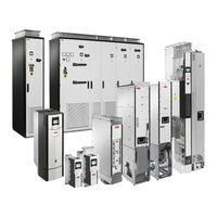
ABB ACS880-04 drive modules Firmware Manual (604 pages)
primary control program
Brand:
ABB
| Category:
Servo Drives
| Size: 5.39 MB
Table of Contents
Table of Contents
5
Safety Instructions
11
Target Audience
11
Introduction to the Manual
11
Applicability
11
What this Chapter Contains
11
Contents of the Manual
12
Related Documents
12
Terms and Abbreviations
13
Cybersecurity Disclaimer
16
Using the Control Panel
17
Control Locations and Operating Modes
19
What this Chapter Contains
19
Local Control Vs. External Control
20
Local Control
20
External Control
21
Operating Modes of the Drive
22
DC Voltage Control Mode
23
Special Control Modes
23
Torque Control Mode
23
Speed Control Mode
23
Frequency Control Mode
23
Program Features
25
What this Chapter Contains
25
Drive Configuration and Programming
26
Programming Via Parameters
26
Adaptive Programming
27
Application Programming
27
Programmable Digital Inputs and Outputs
28
Control Interfaces
28
Programmable Analog Outputs
28
Programmable Analog Inputs
28
Programmable Relay Outputs
29
Programmable I/O Extensions
29
Fieldbus Control
30
Master/Follower Functionality
31
External Controller Interface
39
Control of a Supply Unit (LSU)
41
Motor Control
42
Direct Torque Control (DTC)
42
Reference Ramping
42
Constant Speeds/Frequencies
43
Critical Speeds/Frequencies
43
Speed Controller Autotune
44
Oscillation Damping
47
Resonance Frequency Elimination
48
Rush Control
48
Encoder Support
49
Jogging
55
Scalar Motor Control
58
Autophasing
59
Flux Braking
62
DC Magnetization
63
Hexagonal Motor Flux Pattern
65
Process PID Control
66
Application Macros
66
Application Control
66
Motor Potentiometer
69
Mechanical Brake Control
70
DC Voltage Control
75
Overvoltage Control
75
Undervoltage Control (Power Loss Ride-Through)
75
Voltage Control and Trip Limits
76
Brake Chopper
77
DC Voltage Control Mode
78
Safety and Protections
79
Emergency Stop
79
Motor Thermal Protection
80
Motor Overload Protection
83
Thermal Protection of Motor Cable
84
User Load Curve
84
Automatic Fault Resets
85
Other Programmable Protection Functions
86
Maintenance Timers and Counters
88
Fault and Warning Messages, Data Logging
88
Signal Supervision
88
Diagnostics
88
Energy Saving Calculators
89
Load Analyzer
89
Miscellaneous
91
User Parameter Sets
91
Parameter Checksum Calculation
91
User Lock
92
Reduced Run Function
93
Data Storage Parameters
93
Du/Dt Filter Support
94
Sine Filter Support
95
Router Mode for BCU Control Unit
95
Application Macros
97
What this Chapter Contains
97
General
97
Factory Macro
98
Default Parameter Settings for the Factory Macro
98
Default Control Connections for the Factory Macro
99
Hand/Auto Macro
100
Default Parameter Settings for the Hand/Auto Macro
100
Default Control Connections for the Hand/Auto Macro
101
PID Control Macro
102
Default Parameter Settings for the PID Control Macro
103
Default Control Connections for the PID Control Macro
104
Sensor Connection Examples for the PID Control Macro
105
Torque Control Macro
106
Default Parameter Settings for the Torque Control Macro
106
Default Control Connections for the Torque Control Macro
107
Sequential Control Macro
108
Operation Diagram
108
Selection of Constant Speeds
109
Default Parameter Settings for the Sequential Control Macro
109
Default Control Connections for the Sequential Control Macro
110
Fieldbus Control Macro
111
Parameters
113
What this Chapter Contains
113
Terms and Abbreviations
114
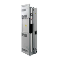
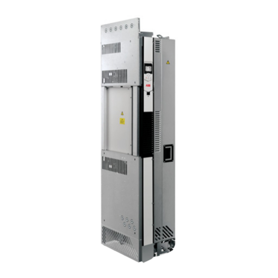
ABB ACS880-04 drive modules Hardware Manual (418 pages)
INDUSTRIAL DRIVES, Single drive module packages
Brand:
ABB
| Category:
Control Unit
| Size: 46.93 MB
Table of Contents
Table of Contents
5
Introduction to the Manual
19
Contents of this Chapter
19
Applicability
19
Safety Instructions
19
Target Audience
19
Contents of the Manual
20
Related Documents
20
Categorization by Frame Size and Option Code
20
Use of Component Designations
20
Terms and Abbreviations
21
Operation Principle and Hardware Description
25
Contents of this Chapter
25
Operation Principle
25
6- and 12-Pulse Supply Units
26
Simplified Main Circuit Diagram
27
Simplified Main Circuit Diagram of the Drive System
27
Single-Line Circuit Diagrams of ACS880-04 Single Drive Module Packages
28
1×D8T + 2×R8I, 6-Pulse
28
2×D8T + 3×R8I, 6-Pulse
29
3×D8T + 3×R8I, 6-Pulse
30
2×D8T + 2×R8I, 12-Pulse
31
4×D8T + 3×R8I, 12-Pulse
32
Hardware of the Supply and Inverter Modules
33
Supply Module (Frame D7T)
34
Supply Module (Frame D8T)
35
Inverter Module (Frame R8I)
36
Connectors X50
37
Overview of Power and Control Connections
39
Simplified Power and Control Connection Diagram
40
Overview of the Control Connections on the BCU Control Unit
42
Control Devices
43
Main Disconnecting Device
43
Auxiliary Voltage Switch
43
Operating Switch
43
Emergency Stop and Emergency Stop Reset Buttons
43
The BCU Control Unit
43
The ACS-AP-X Control Panel
43
PC Connection
44
Fieldbus Control
44
Type Designation Labels
45
Type Designation Key
46
Moving and Unpacking the Modules
47
Contents of this Chapter
47
Moving and Lifting the Transport Package
47
Unpacking
47
Lifting the Modules
48
Moving the Modules
48
Cabinet Construction
49
Contents of this Chapter
49
Liability
49
Switching, Disconnecting and Protecting Solution
49
Cabinet Configuration Overview
50
ACS880-04 Configurations in Rittal TS 8 Enclosures, 6-Pulse
50
ACS880-04 Configurations in Generic Enclosures, 6-Pulse
51
ACS880-04 Configurations in Rittal TS 8 Enclosures, 12-Pulse
52
ACS880-04 Configurations in Generic Enclosures, 12-Pulse
53
Supply Unit with D8T Modules (Rittal TS 8 Enclosure, 6-Pulse)
54
Supply Unit with D7T Modules (Rittal TS 8 Enclosure, 12-Pulse)
55
Supply Unit with D8T Modules (Rittal TS 8 Enclosure, 12-Pulse)
56
Inverter Unit with R8I Modules (Rittal TS 8 Enclosure, 6- and 12-Pulse)
57
ACS880-04 Single Drive Module Package
58
Incoming Cubicle
59
Example of the AC Fuse Cooling
59
RFI Filter
61
Installation Examples
62
1×D8T Module in Rittal TS 8 Enclosure (6-Pulse)
62
Kits for 1×D8T
63
Stage 1: Installation of Common Parts
64
Stage 2: Module Installation
65
Stage 3: Quick Connector Installation
66
Stage 4: DC Busbars
67
Stage 5: AC Busbars to Quick Connector
68
Stage 6: AC Busbar Installation
69
Stage 7: Module Installation
70
Stage 8: Shroud Installation
71
1×D8T Module in Generic Enclosure (6-Pulse)
72
2×D8T Modules in Rittal TS 8 Enclosure (6-Pulse)
73
Kits for 2×D8T
74
Stage 1: Installation of Common Parts
75
Stage 2: Module Installation
76
Stage 3: Quick Connector Installation
77
Stage 4: DC Busbars
78
Stage 5: AC Busbars to Quick Connector
79
Stage 6: AC Fuse Busbars Installation
80
Stage 7: Module Installation
81
Stage 8: Shroud Installation
82
2×D8T Modules in Generic Enclosure (6- and 12-Pulse)
83
3×D8T Modules in Generic Enclosure (6-Pulse)
84
1×R8I Module in Rittal TS 8 Enclosure (6- and 12-Pulse)
85
Kits for 1×R8I
86
Stage 1: Installation of Common Parts
87
Stage 2: DC Busbars and DC Connection
88
Stage 3: Module Installation and Lead-Through for Bottom Plate Installation
89
Stage 4A: AC Busbars and Quick Connector Installation
90
Stage 4B: Common AC Output Busbars and AC Busbars Installation
91
Stage 5: Common Mode Busbars and DC Connection Flanges Installation
92
Stage 6: Shroud Installation Parts
93
Stage 7: Module Installation
94
2×R8I Modules in Rittal TS 8 Enclosure (6- and 12-Pulse)
95
Kits for 2×R8I
96
Stage 1: Installation of Common Parts
97
Stage 2: DC Busbars and DC Connection
98
Stage 3: Module Installation Parts and Lead-Through for Bottom Plate
99
Stage 4A: AC Output Busbars and Quick Connector Installation
100
Stage 4B: AC Output Interconnection Busbars and Quick Connectors
101
Installation
102
Stage 5: Common Mode Busbars and DC Connection Flanges Installation
103
Stage 6: Shroud Installation Parts
104
Stage 7: Module Installation
105
2×R8I Modules in Generic Enclosure (6- and 12-Pulse)
106
3×R8I Modules in Generic Enclosure (6- and 12-Pulse)
107
2×D7T Modules in Rittal TS 8 Enclosure (12-Pulse)
108
Kits for 2×D7T
109
Stage 1: Installation of Common Parts
110
Stage 2: Module Installation Parts
111
Stage 3: Module Installation
112
Stage 4: AC Busbars to the Module
113
Stage 5: DC Busbars
114
Stage 6: Shroud Installation
115
2×D8T Modules in Rittal TS 8 Enclosure (12-Pulse)
116
Kits for 2×D8T, 12-Pulse
117
Stage 1: Installation of Common Parts
118
Stage 2: Module Installation Parts
119
Stage 3: Quick Connectors
120
Stage 4: DC Busbar Installation
121
Stage 5: AC Busbars to Quick Connector
122
Stage 6: AC Busbars to Main AC Installation
123
Stage 7: Module Installation, DC Connection Flanges
124
Stage 8: Shroud Installation
125
4×D8T Modules in Rittal TS 8 Enclosure (12-Pulse)
126
4×D8T Modules in Generic Enclosure (12-Pulse)
126
Advertisement
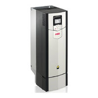
ABB ACS880-04 drive modules Firmware Manual (566 pages)
Industrial drives, Primary control program
Brand:
ABB
| Category:
Servo Drives
| Size: 4.92 MB
Table of Contents
Table of Contents
5
List of Related Manuals
2
Table of Contents
5
Introduction to the Manual
11
What this Chapter Contains
11
Applicability
11
Safety Instructions
11
Target Audience
11
Contents of the Manual
12
Related Documents
12
Terms and Abbreviations
13
Using the Control Panel
17
Control Locations and Operating Modes
19
What this Chapter Contains
19
Local Control Vs. External Control
20
Local Control
20
External Control
21
Operating Modes of the Drive
22
Speed Control Mode
23
Torque Control Mode
23
Frequency Control Mode
23
Special Control Modes
23
Program Features
25
What this Chapter Contains
25
Drive Configuration and Programming
26
Programming Via Parameters
26
Adaptive Programming
27
Application Programming
29
Control Interfaces
30
Programmable Analog Inputs
30
Programmable Analog Outputs
30
Programmable Digital Inputs and Outputs
30
Programmable Relay Outputs
30
Programmable I/O Extensions
31
Fieldbus Control
32
Master/Follower Functionality
33
External Controller Interface
40
Control of a Supply Unit (LSU)
42
Motor Control
44
Direct Torque Control (DTC)
44
Reference Ramping
44
Constant Speeds/Frequencies
45
Critical Speeds/Frequencies
45
Speed Controller Autotune
46
Oscillation Damping
49
Rush Control
50
Encoder Support
51
Jogging
57
Scalar Motor Control
60
Autophasing
61
Flux Braking
63
DC Magnetization
64
Application Control
67
Application Macros
67
Process PID Control
67
Motor Potentiometer
70
Mechanical Brake Control
71
DC Voltage Control
76
Overvoltage Control
76
Undervoltage Control (Power Loss Ride-Through)
76
Voltage Control and Trip Limits
77
Brake Chopper
78
Safety and Protections
79
Emergency Stop
79
Motor Thermal Protection
80
Thermal Protection of Motor Cable
83
User Load Curve
83
Other Programmable Protection Functions
84
Automatic Fault Resets
86
Diagnostics
87
Fault and Warning Messages, Data Logging
87
Signal Supervision
87
Maintenance Timers and Counters
87
Energy Saving Calculators
88
Load Analyzer
88
Miscellaneous
90
User Parameter Sets
90
Parameter Checksum Calculation
90
User Lock
91
Data Storage Parameters
91
Reduced Run Function
91
Du/Dt Filter Support
92
Sine Filter Support
93
Application Macros
95
What this Chapter Contains
95
General
95
Factory Macro
96
Default Parameter Settings for the Factory Macro
96
Default Control Connections for the Factory Macro
97
Hand/Auto Macro
98
Default Parameter Settings for the Hand/Auto Macro
98
Default Control Connections for the Hand/Auto Macro
99
PID Control Macro
100
Default Parameter Settings for the PID Control Macro
101
Default Control Connections for the PID Control Macro
102
Sensor Connection Examples for the PID Control Macro
103
Torque Control Macro
104
Default Parameter Settings for the Torque Control Macro
104
Default Control Connections for the Torque Control Macro
105
Sequential Control Macro
106
Operation Diagram
106
Selection of Constant Speeds
107
Default Parameter Settings for the Sequential Control Macro
107
Default Control Connections for the Sequential Control Macro
108
Fieldbus Control Macro
109
Parameters
111
What this Chapter Contains
111
Terms and Abbreviations
112
ABB ACS880-04 drive modules Hardware Manual (316 pages)
Single drive modules
Brand:
ABB
| Category:
DC Drives
| Size: 51.74 MB
Table of Contents
Table of Contents
5
1 Safety Instructions
17
Contents of this Chapter
17
Use of Warnings and Notes
17
General Safety in Installation, Start-Up and Maintenance
18
Electrical Safety in Installation, Start-Up and Maintenance
20
Electrical Safety Precautions
20
Additional Instructions and Notes
22
Optical Components
23
Printed Circuit Boards
23
Grounding
23
General Safety in Operation
24
Additional Instructions for Permanent Magnet Motor Drives
25
Safety in Installation, Start-Up, Maintenance
25
Safety in Operation
25
2 Introduction to the Manual
27
Contents of this Chapter
27
Applicability
27
Target Audience
27
Purpose of the Manual
27
Categorization by Frame Size and Option Code
28
Quick Installation, Commissioning and Operating Flowchart
28
21 Resistor Braking
28
Terms and Abbreviations
30
Related Documents
33
3 Operation Principle and Hardware Description
35
Contents of this Chapter
35
Product Overview
36
Layout
37
Standard Drive Module Configuration with Option +E208
37
Drive Module for Flat Mounting (Option +C173)
39
Drive Module with Full Power Cabling Panels (Option +H381)
41
Drive Module Without Full-Size Output Cable Connection Terminals (Option +0H371) and IP20 Shrouds (Option +0B051)
42
Drive Module Configuration with Power Cable Connection Terminals on the Right-Hand Side of the Drive Module (Option +H391)
43
Control Unit
44
Control Panel
44
Overview of Power and Control Connections
46
Type Designation Label
47
Type Designation Key
47
Basic Code
48
Option Codes
48
4 Generic Cabinet Planning Instructions
53
Contents of this Chapter
53
Limitation of Liability
53
Cabinet Construction
53
Disposition of the Devices
54
Grounding of Mounting Structures
54
Busbar Material and Joints
54
Shrouds
54
Tightening Torques
54
Electrical Connections
54
Cable Lugs
55
Insulation Supports
55
Mechanical Connections
55
Cooling and Degrees of Protection
55
Planning the Cooling
55
Air Inlets and Outlets
56
Preventing the Recirculation of Hot Air
57
EMC Requirements
58
Attaching the Cabinet
60
Cabinet Placement on a Cable Channel
60
Heaters
60
Mounting the Control Panel on the Cabinet Door
61
5 Guidelines for Planning the Mechanical Installation
63
Contents of this Chapter
63
Installation Positions of the Drive Module
63
Planning the Layout
64
Layout Example, Door Closed
64
Layout Example, Door Open (Standard Drive Module Configuration)
65
Layout Example, Door Open (Option +H391)
66
Layout Example, Door Open (Option +0B051)
68
Bookshelf Mounting (Standard Drive Module Configuration)
70
Bookshelf Mounting (Option +0B051)
71
Bookshelf Mounting (Option +H381)
73
Flat Mounting (Option +C173)
74
Flat Mounting (Option +C173 + 0B051)
75
Free Space Requirements
76
Free Space at the Top of the Drive Module
76
Free Space Around the Drive Module
77
Other Installation Positions than Vertical
77
Placement of the Control Panel
77
ABB Air Inlet and Outlet Kits
77
6 Mechanical Installation
79
Contents of this Chapter
79
Safety
79
Examining the Installation Site
80
Moving and Unpacking the Unit
80
Package Drawings
82
Examining the Delivery
87
Lifting the Drive Module
87
Installation Alternatives
87
Standard Drive Module Configuration (Bookshelf Mounting)
87
Drive Module Configuration for Flat Mounting (Option +C173)
87
Optional Input Power Cable Connection Terminals and Ground Busbar Assembly (+H370)
88
Drive Module with Full Cabling Panels (Option +H381)
88
Drive Module Without Full-Size Output Cable Connection Terminals (Option +0H371) and IP20 Shrouds (Option +0B051)
89
Drive Module Configuration with Power Cable Connection Terminals on the Right-Hand Side of the Drive Module (Option +H391)
89
Drive Module Without Pedestal (Option +0H354)
89
Attaching the Drive Module to a Mounting Plate or Wall
89
Attaching the Drive Module to a Mounting Plate or Wall (Option +H391)
90
Attaching the External Control Unit
90
Attaching the External Control Unit to a Mounting Plate or Wall
91
Attaching the External Control Unit Vertically on a DIN Rail
91
Attaching the External Control Unit Horizontally on a DIN Rail
92
Alternatives for Grounding the Drive Module
92
Installing the Bottom Grille for IP20 Degree of Protection
94
ABB ACS880-04 drive modules Hardware Manual (276 pages)
drive modules
Brand:
ABB
| Category:
Control Unit
| Size: 49.2 MB
Table of Contents
Table of Contents
5
Safety Instructions
15
Contents of this Chapter
15
Use of Warnings and Notes
15
General Safety in Installation, Start-Up and Maintenance
16
Electrical Safety in Installation, Start-Up and Maintenance
19
Electrical Safety Precautions
19
Additional Instructions and Notes
20
Printed Circuit Boards
20
Grounding
21
General Safety in Operation
22
Additional Instructions for Permanent Magnet Motor Drives
22
Safety in Installation, Start-Up, Maintenance
22
Safety in Operation
23
Introduction to the Manual
25
Contents of this Chapter
25
Target Audience
25
Categorization by Frame Size and Option Code
25
Quick Installation, Commissioning and Operating Flowchart
26
Terms and Abbreviations
27
Related Documents
29
Operation Principle and Hardware Description
31
Contents of this Chapter
31
Product Overview
32
Layout
33
Standard Drive Module Configuration with Option +E208
33
Drive Module for Flat Mounting (Option +C173)
35
Drive Module with Full Power Cabling Panels (Option +H381)
36
Drive Module Without Full-Size Output Cable Connection Terminals (Option +0H371) and IP20 Shrouds (Option +0B051)
37
Drive Module Configuration with Power Cable Connection Terminals on the Right-Hand Side of the Drive Module (Option +H391)
38
Control Unit
39
Control Panel
39
Overview of Power and Control Connections
40
Type Designation Label
40
Type Designation Key
41
Basic Code
41
Option Codes
42
Guidelines for Planning the Mechanical Installation
45
Contents of this Chapter
45
Installation Positions of the Drive Module
46
Planning the Layout
47
Layout Example, Door Closed
47
Layout Example, Door Open (Standard Drive Module Configuration)
48
Layout Example, Door Open (Option +H391)
49
Layout Example, Door Open (Option +0B051)
50
Bookshelf Mounting (Standard Drive Module Configuration)
51
Bookshelf Mounting (Option +0B051)
52
Bookshelf Mounting (Option +H381)
53
Flat Mounting (Option +C173)
54
Flat Mounting (Option +C173 + 0B051)
55
Free Space Requirements
56
Free Space at the Top of the Drive Module
56
Free Space Around the Drive Module
56
Free Space below the Drive Module
56
Installation Positions Other than Vertical
57
ABB Air Inlet and Outlet Kits
57
Mechanical Installation
59
Contents of this Chapter
59
Safety
60
Examining the Installation Site
60
Moving and Unpacking the Unit
61
Moving the Drive Module
61
Unpacking
61
Package Drawings
62
Examining the Delivery
66
Lifting the Drive Module
66
Installation Alternatives
66
Standard Drive Module Configuration (Bookshelf Mounting)
67
Drive Module Configuration for Flat Mounting (Option +C173)
67
Optional Input Power Cable Connection Terminals and Ground Busbar Assembly (+H370)
67
Drive Module with Full Cabling Panels (Option +H381)
68
Drive Module Without Full-Size Output Cable Connection Terminals (Option +0H371) and IP20 Shrouds (Option +0B051)
68
Drive Module Configuration with Power Cable Connection Terminals on the Right-Hand Side of the Drive Module (Option +H391)
68
Drive Module Without Wheeled Pedestal (Option +0H354)
69
Attaching the Drive Module to a Mounting Plate or Wall
69
Attaching the Drive Module to a Mounting Plate or Wall (Option +H391)
69
Attaching the External Control Unit
69
Attaching the External Control Unit to a Mounting Plate or Wall
70
Attaching the External Control Unit Vertically on a DIN Rail
70
Attaching the External Control Unit Horizontally on a DIN Rail
71
Alternatives for Grounding the Drive Module
71
Installing the Bottom Grille for IP20 Degree of Protection
73
Guidelines for Planning the Electrical Installation
75
Contents of this Chapter
75
Limitation of Liability
75
Selecting the Main Supply Disconnecting Device
75
European Union and United Kingdom
75
North America
76
Other Regions
76
Selecting the Main Contactor
76
Examining the Compatibility of the Motor and Drive
76
Protecting the Motor Insulation and Bearings
77
Requirements Tables
77
Requirements for ABB Motors, P
77
Kw (134 Hp)
77
Requirements for ABB Motors, P
78
Kw (134 Hp)
78
Requirements for Non-ABB Motors, P
79
Kw (134 Hp)
79
Requirements for Non-ABB Motors, P
80
Kw (134 Hp)
80
Abbreviations
80
Availability of D U /D T Filter and Common Mode Filter by Drive Type
81
Additional Requirements for Explosion-Safe (EX) Motors
81
HX_ and am
81
Additional Requirements for Braking Applications
81
Additional Requirements for ABB High-Output and IP23 Motors
81
Additional Requirements for Non-ABB High-Output and IP23 Motors
81
Additional Data for Calculating the Rise Time and the Peak Line-To-Line Voltage
82
Additional Note for Sine Filters
83
Selecting the Power Cables
83
General Guidelines
83
Typical Power Cable Sizes
84
Power Cable Types
84
Preferred Power Cable Types
84
Alternate Power Cable Types
84
Not Allowed Power Cable Types
85
Additional Guidelines, North America
86
Metal Conduit
86
Power Cable Shield
86
Grounding Requirements
87
Additional Grounding Requirements - IEC
88
Additional Grounding Requirements - UL (NEC)
88
Selecting the Control Cables
88
Shielding
88
Signals in Separate Cables
89
Signals that Can be Run in the same Cable
89
ABB ACS880-04 drive modules Hardware Manual (254 pages)
200 to 710 kW, 300 to 700 hp
Brand:
ABB
| Category:
Controller
| Size: 29.32 MB
Table of Contents
List of Related Manuals
2
Table of Contents
5
1 Safety Instructions
15
Contents of this Chapter
15
Use of Warnings and Notes
15
General Safety in Installation, Start-Up and Maintenance
16
Electrical Safety in Installation, Start-Up and Maintenance
18
Precautions before Electrical Work
18
Additional Instructions and Notes
19
Grounding
20
Additional Instructions for Permanent Magnet Motor Drives
21
Safety in Installation, Start-Up and Maintenance
21
2 Introduction to the Manual
23
Contents of this Chapter
23
Target Audience
23
Contents of the Manual
24
Categorization by Frame Size and Option Code
25
Quick Installation, Commissioning and Operating Flowchart
25
Terms and Abbreviations
27
3 Operation Principle and Hardware Description
29
Contents of this Chapter
29
Product Overview
30
Layout
31
Standard Drive Module Configuration with Option +E208
31
Drive Module for Flat Mounting (Option +C173)
33
Drive Module with Full Power Cabling Panels (Option +H381)
34
Drive Module Without Full-Size Output Cable Connection Terminals (Option +0H371) and IP20 Shrouds (Option +0B051)
35
Drive Module Configuration with Power Cable Connection Terminals on the Right-Hand Side of the Drive Module (Option +H391)
36
Control Unit
37
Control Panel
37
Overview of Power and Control Connections
38
External Control Connection Terminals
39
External Control Unit Connection Cables
40
Type Designation Label
40
Type Designation Key
41
4 Guidelines for Planning the Cabinet Installation
45
Contents of this Chapter
45
Limitation of Liability
45
Installation Positions of the Drive Module
45
Basic Requirements for the Cabinet
45
Planning the Layout of the Cabinet
46
Layout Example, Door Closed
46
Layout Example, Door Open (Standard Drive Module Configuration)
47
Layout Example, Door Open (Option +H391)
48
Layout Example, Door Open (Option +0B051)
49
Arranging the Grounding Inside the Cabinet
50
Selecting the Busbar Material and Preparation of the Joints
50
Tightening Torques
50
Planning the Fastening of the Cabinet
50
Planning the Cabinet Placement on a Cable Channel
51
Planning the Electromagnetic Compatibility (EMC) of the Cabinet
51
Planning the Cooling
52
Preventing the Recirculation of Hot Air
54
Bookshelf Mounting (Standard Drive Module Configuration)
55
Bookshelf Mounting (Option +0B051)
56
Bookshelf Mounting (Option +H381)
57
Flat Mounting (Option +C173)
58
Flat Mounting (Option +C173+0B051)
59
Required Free Space
60
Free Space at the Top of the Drive Module
60
Free Space Around the Drive Module
60
Other Installation Positions
60
Drive Module on Its Back
60
Planning the Placement of the Control Panel
61
Planning the Use of Cubicle Heaters
61
ABB Air Inlet and Outlet Kits
61
5 Guidelines for Planning the Electrical Installation
63
Contents of this Chapter
63
Selecting the Supply Disconnecting Device
64
European Union
64
Other Regions
64
Selecting the Main Contactor
64
Examining the Compatibility of the Motor and Drive
64
Protecting the Motor Insulation and Bearings
65
Requirements Table
65
Additional Requirements for Explosion-Safe (EX) Motors
67
Additional Requirements for ABB Motors of Types Other than M2_, M3_, M4_, HX_ and am
67
Additional Requirements for the Braking Applications
67
Additional Requirements for ABB High-Output and IP23 Motors
67
Additional Requirements for Non-ABB High-Output and IP23 Motors
67
Additional Data for Calculating the Rise Time and the Peak Line-To-Line Voltage
68
Additional Note for Sine Filters
68
Additional Note for Common Mode Filters
68
Selecting the Power Cables
69
General Rules
69
Typical Power Cable Sizes
70
Alternative Power Cable Types
71
Recommended Power Cable Types
71
Power Cable Types for Restricted Use
71
Not Allowed Power Cable Types
71
Motor Cable Shield
72
Additional US Requirements
72
Conduit
72
Armored Cable / Shielded Power Cable
72
Planning the Braking System
73
Selecting the Control Cables
73
Shielding
73
Signals in Separate Cables
73
Signals Allowed to be Run in the same Cable
73
Relay Cable Type
73
Control Panel Cable Length and Type
73
Routing the Cables
73
Separate Control Cable Ducts
74
Continuous Motor Cable Shield or Enclosure for Equipment in the Motor Cable
74
Implementing Thermal Overload and Short-Circuit Protection
75
Protecting the Drive and Input Power Cable in Short-Circuits
75
Circuit Breakers
75
Protecting the Motor and Motor Cable in Short-Circuits
76
Protecting the Drive and the Input Power and Motor Cables against Thermal Overload
77
Protecting the Motor against Thermal Overload
77
Protecting the Drive against Ground Faults
77
Residual Current Device Compatibility
77
Connecting Drive Modules to a Common DC System
77
Implementing the Emergency Stop Function
78
Implementing the Safe Torque off Function
78
Implementing the ATEX-Certified Safe Motor Disconnection Function (Option +Q971)
78
(Options +Q972 and +Q973)
78
Declaration of Conformity
78
Implementing the Power Loss Ride-Through Function
79
Using Power Factor Compensation Capacitors with the Drive
79
Implementing a Safety Switch between the Drive and the Motor
79
Using a Contactor between the Drive and the Motor
80
Implementing a Bypass Connection
80
Example Bypass Connection
81
Switching the Motor Power Supply from Drive to Direct-On-Line
81
Switching the Motor Power Supply from Direct-On-Line to Drive
82
Protecting the Contacts of Relay Outputs
82
Implementing a Motor Temperature Sensor Connection
83
Drive I/O, I/O Extension and Encoder Interface Modules
83
Example Circuit Diagram
84
ABB ACS880-04 drive modules Quick Installation And Start-Up Manual (274 pages)
INDUSTRIAL DRIVES
Brand:
ABB
| Category:
DC Drives
| Size: 11.35 MB
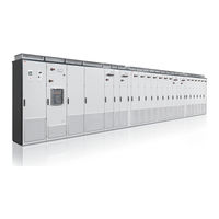
ABB ACS880-04 drive modules Electrical Planning Instructions (52 pages)
Multidrive cabinets and modules
Brand:
ABB
| Category:
Industrial Electrical
| Size: 2.53 MB
Table of Contents
Table of Contents
5
1 Introduction to the Manual
9
Contents of this Chapter
9
Applicability
9
Target Audience
9
Terms and Abbreviations
9
Related Manuals
11
Cabinet-Installed Multidrive Manuals
11
Multidrive Module Manuals
11
2 Electrical Planning Guidelines
13
Contents of this Chapter
13
Limitation of Liability
13
Selecting the Supply Disconnecting Device
13
Cabinet-Installed Multidrives
13
Multidrive Modules
13
Selecting the Main Contactor (Breaker)
14
Cabinet-Installed Multidrives
14
Multidrive Modules
14
Selecting the Supply Transformer
15
Basic Guidelines
15
Additional Notes
16
A Drive Larger than 500 Kva with an IGBT Supply Unit or a Regenerative Rectifier Unit
16
A Drive with a 12-Pulse Diode Supply Unit
17
Two Parallel-Connected Supply Units
17
Examining the Compatibility of the Motor and Drive
18
Protecting the Motor Insulation and Bearings
18
Requirements Table
18
Availability of Du/Dt Filter and Common Mode Filter by Drive Type
21
Additional Requirements for Explosion-Safe (EX) Motors
21
And am
21
Additional Requirements for Braking Applications
21
Additional Requirements for Drives with an IGBT Supply Unit or Regenerative Rectifier Unit
21
Additional Requirements for ABB High-Output and IP23 Motors
21
Additional Requirements for Non-ABB High-Output and IP23 Motors
22
Additional Data for Calculating the Rise Time and the Peak Line-To-Line Voltage
23
Additional Note for Sine Filters
23
Selecting the Power Cables
24
General Rules
24
Typical Power Cable Sizes
24
Alternative Power Cable Types
25
Recommended Power Cable Types
25
Power Cable Types for Limited Use
25
Not Allowed Power Cable Types
26
Power Cable Shield
26
Additional US Requirements
27
Metal Conduit
27
Selecting the Control Cables
28
Shielding
28
Signals in Separate Cables
28
Signals that Can be Run in the same Cable
28
Relay Cable Type
28
Control Panel Cable Length and Type
28
Routing the Cables
29
Guidelines for Routing the Cables
29
Separate Control Cable Ducts
30
Continuous Motor Cable Shield or Enclosure for Equipment on the Motor Cable
30
Implementing Thermal Overload and Short Circuit Protections
31
Protecting the Input Power Cable against Thermal Overload
31
Protecting the Input Power Cable in Short-Circuits
31
Protecting the Drive against Thermal Overload
31
Cabinet-Installed Multidrives
31
Multidrive Modules
31
Protecting against Short-Circuit Inside the Drive
31
Multidrive Modules
32
Protecting the Motor and Motor Cable in Short-Circuits
32
Protecting the Motor Cables against Thermal Overload
32
Protecting the Motor against Thermal Overload
32
Implementing a Motor Temperature Sensor Connection
33
Connection of Motor Temperature Sensor to the Drive Via an Option Module
33
Implementing a Ground Fault Protecting Function
34
Cabinet-Installed Multidrives
34
Residual Current Device Compatibility
34
Multidrives Modules
34
Implementing the Emergency Stop Function
35
Cabinet-Installed Multidrives
35
Multidrive Modules
35
Implementing the Safe Torque off Function
35
Implementing the Prevention of Unexpected Start-Up Function
36
Cabinet-Installed Multidrives
36
Multidrive Modules
36
Implementing the Safely-Limited Speed Function
36
Implementing the Functions Provided by the FSO-XX Safety Functions Module
36
Multidrive Modules
37
Supplying Power for the Auxiliary Circuits
37
Cabinet-Installed Multidrives
37
Using Power Factor Compensation Capacitors with the Drive
37
Using a Safety Switch between the Drive and the Motor
37
Implementing the Power-Loss Ride-Through
38
Cabinet-Installed Drives with Main Contactor (Option +F250)
38
Implementing the Control of a Contactor between Drive and Motor
38
Implementing a Bypass Connection
39
Protecting the Contacts of Relay Outputs
39
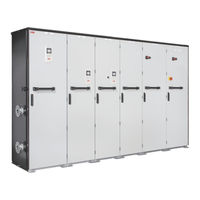
ABB ACS880-04 drive modules Electrical Planning Manual (50 pages)
liquid-cooled multidrive cabinets and modules
Brand:
ABB
| Category:
Industrial Equipment
| Size: 1.33 MB
Table of Contents
Table of Contents
5
Introduction to the Manual
9
Contents of this Chapter
9
Applicability
9
Safety Instructions
9
Target Audience
9
Terms and Abbreviations
10
Related Documents
11
Cabinet-Installed Multidrive Manuals
11
Multidrive Module Manuals
11
Electrical Planning Guidelines
13
Contents of this Chapter
13
Limitation of Liability
13
Selecting the Supply Disconnecting Device
13
Cabinet-Installed Multidrives
13
Multidrive Modules
13
European Union
13
North America
14
Other Regions
14
Selecting the Main Contactor (Breaker)
14
Cabinet-Installed Multidrives
14
Multidrive Modules
14
Selecting the Supply Transformer
15
Cabinet-Installed Multidrives
15
Basic Guidelines
15
Additional Notes
16
Multidrive Modules
17
IGBT Supply Modules ACS880-204LC
17
Diode Supply Modules ACS880-304LC+A019
17
Examining the Compatibility of the Motor and Drive
18
Protecting the Motor Insulation and Bearings
18
Requirements Table
18
Availability of Du/Dt Filter and Common Mode Filter by Drive or Inverter Type
21
Additional Requirements for Explosion-Safe (EX) Motors
21
And am
21
Additional Requirements for Braking Applications
21
Additional Requirements for Drives with an IGBT Supply Unit or Regenerative Rectifier Unit
21
Additional Requirements for ABB High-Output and IP23 Motors
21
Additional Requirements for Non-ABB High-Output and IP23 Motors
22
Additional Note for Sine Filters
22
Selecting the Power Cables
23
General Guidelines
23
Typical Power Cable Sizes
23
Power Cable Types
24
Recommended Power Cable Types
24
Alternate Power Cable Types
24
Not Allowed Power Cable Types
25
Power Cable Shield
25
Selecting the Control Cables
27
Shielding
27
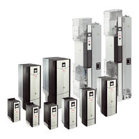
ABB ACS880-04 drive modules Application Manual (48 pages)
drives and drive modules
Brand:
ABB
| Category:
DC Drives
| Size: 0.89 MB
Table of Contents
List of Related Manuals
2
Table of Contents
5
Introduction to the Manual
7
Contents of this Chapter
7
Applicability
7
Safety Instructions
7
Target Audience
7
Contents of the Manual
7
Related Documents
8
Categorization by Frame Size
8
Quick Planning Guide
8
Terms and Abbreviations
9
Operation Principle and Hardware Description
11
Contents of this Chapter
11
Operation Basics
12
Overview of the Common DC System
13
Overview Diagram of the Common DC System
13
Benefits of the Common DC System
14
Challenges of the Common DC System
14
Overview Diagram of the Drive Main Circuit
15
Charging Circuit Types
15
Type a
15
Type B
15
Brake Chopper Types
15
Planning - Basics
17
Contents of this Chapter
17
Defining the DC Link Duty Cycle and Key Variables
18
Defining the DC Link Duty Cycle
18
DC Link Duty Cycle Diagram
19
DC Link Key Variables
19
Selecting the Drives Which Are Connected to AC Power Line
21
The Selection Rules
21
Calculating the Rectifier Power Capacity
21
Verifying the Charging Capacity of the Common DC System
22
Checking the Total Charging Resistance
23
Checking the Peak AC Current at Charging
24
Checking the Charging Energy
24
Handling the Surplus Energy
25
Background
25
Defining the Energy Absorbing Capacity of the Common DC Link
26
Defining the Maximum DC Link Voltage
27
Selecting the Brake Choppers and Resistors
27
Brake Chopper Selection Formulas
28
Brake Resistor Selection Formulas - System with One Brake Chopper
28
Brake Resistor Selection Formulas - System with Several Brake Choppers and Resistors
29
Planning - Additional Instructions
31
Contents of this Chapter
31
Requirements for the AC Input Connection
31
Constructing the DC Link
31
Selecting the Fuses
32
Selecting the AC Input Fuses
32
Selecting the DC Fuses
32
Phase Loss Protection
33
Selecting the Power Cables
33
DC Contactors
34
DC Link Separation
34
Brake Resistor Protection
34
Electromagnetic Compatibility (EMC)
35
Connecting the Ready and Start Enable Signals
36
Setting the Drive Parameters
37
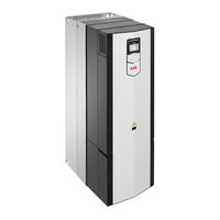
ABB ACS880-04 drive modules Application Manual (46 pages)
ATEX-certified Safe disconnection function, Ex II 2 GD for drives option +Q971
Brand:
ABB
| Category:
DC Drives
| Size: 1.79 MB
Table of Contents
Table of Contents
5
1 Safety Instructions
7
Contents of this Chapter
7
Use of Warnings and Notes
7
ATEX-Certified Motor Thermal Protection Functions
7
Electrical Safety Precautions
9
2 Introduction
11
Contents of this Chapter
11
Applicability
11
Target Audience
11
The ATEX-Certified Safe Disconnection Function
11
Commissioning the Drive for a Motor in a Hazardous Area
11
Compliance with the European ATEX Product Directive 2014/34/EU
12
Exclusion of Liability
12
Terms and Abbreviations
12
Related Manuals
13
3 Implementing a Motor Thermal Protection Circuit
15
Contents of this Chapter
15
Overview
15
Two-Channel Connection to Drive STO Terminals
16
General
16
Implementing the Reset of the Safety Function
16
Indications of the Safety Function
16
Connection Diagram
17
One-Channel Connection to Drive STO Terminals
18
General
18
Implementing the Reset of the Safety Function
18
Indications of the Safety Function
18
Connection Diagram
19
One-Channel or Two-Channel Connection to an FSO Module
20
General
20
Implementing the Reset of the Safety Function
20
Indications of the Safety Function
20
Connection Diagram (Two-Channel Connection)
21
Connection Diagram (One-Channel Connection)
22
Sensors
22
Protection Relays
23
Wiring
23
Insulation of the Sensor Circuit
23
General Wiring Instructions
23
4 Parameter Settings
25
Contents of this Chapter
25
Drive / Inverter
25
Switching Frequency Limitation
25
Reset Method and Status Indications
25
31.22 STO Indication Run/Stop
25
Motor Overtemperature Indication
26
31.11 Fault Reset Selection
26
Other Recommended Settings
26
FSO Module
27
General Parameters
27
Parameters for the STO Function
29
Parameters for the SSE Function
31
Parameters for the SS1 Function
31
SS1 Ramp Parameters in the Drive/Inverter Unit
33
FSE Module and Safety Pulse Encoder Parameters
33
Mechanical Brake Control
34
ABB ACS880-04 drive modules Quick Installation Manual (92 pages)
drive modules 200 to 710 kW, 300 to 700 hp
Brand:
ABB
| Category:
Servo Drives
| Size: 5.95 MB
ABB ACS880-04 drive modules Application Supplement (28 pages)
+C132 marine type-approved drives
Brand:
ABB
| Category:
DC Drives
| Size: 0.77 MB
Table of Contents
Table of Contents
5
ACS880-01/04 +C132 Marine Type-Approved Drives
7
Safety Instructions
7
Introduction to the Manual
7
Applicability
7
Target Audience
7
Related Manuals
8
Product Overview - ACS880-01 +C132
10
Layout (IP21, UL Type 1)
10
Type Code Designation
11
Product Overview - ACS880-04 +C132
11
Mechanical Installation
11
Wall Installation of Frame Sizes R1 to R3
11
Wall Installation of Frame Sizes R4 to R9
11
Cabinet Installation of Frame Sizes R1 to R9
11
Cabinet Installation of Frame Sizes R10 and R11
11
Electrical Installation
12
Ungrounded) Networks
12
Connecting the Power Cables
12
Connection Diagram
12
Connection Procedure - ACS880-01
12
Connection Procedure - ACS880-04
12
Technical Data
13
Ratings - ACS880-01 +C132
13
Iec Ratings - Acs880-01 +C132
13
Ul (Nec) Ratings - Acs880-01 +C132
16
Definitions - ACS880-01
18
Ratings - ACS880-04 +C132
20
Iec Ratings - Acs880-04 +C132
20
Definitions - ACS880-04
21
Ul (Nec) Ratings - Acs880-04 +C132
21
Ambient Temperature Derating
22
ACS880-04 Drive Modules, ACS880-01 IP21 (UL Type 1) Drive Types and Other IP55 (UL Type 12) Types than Listed in the Following Subheadings
22
ACS880-01 IP55 (UL Type 12) Drive Types -274A-2, 293A-3, -247A-4, -260A-5, -302A-5 and -174A-7
23
ACS880-01 IP55 (UL Type 12) Drive Types -228A-4 and -240A-5
24
ACS880-01 IP55 (UL Type 12) Drive Types -363A-3, -343A-4 and -361A-5
25
ACS880-01 IP55 (UL Type 12) Drive Type -210A-7
26
ACS880-01 IP55 (UL Type 12) Types -0430A-3, -393A-4, -0414A-5 and -0271A-7
26
Marine Type Approvals
26
ABB ACS880-04 drive modules Quick Installation Instructions (50 pages)
Brand:
ABB
| Category:
Industrial Equipment
| Size: 9.86 MB
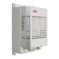
ABB ACS880-04 drive modules User Manual (22 pages)
ABB LV AC DRIVE PIHF Harmonic Filters
Brand:
ABB
| Category:
DC Drives
| Size: 0.92 MB
Table of Contents
Table of Contents
3
1 Manual Introduction
5
2 Safety Instructions
5
Contents
5
Safety of Installation and Maintenance
5
3 Guide on Installation and Debugging of Filters
7
Contents
7
Product Overview
7
Mechanical Installation
11
Electrical Connection
12
Model Information
14
Technical Data
16
Further Information
21
Product and Service Inquiries
21
Product Training
21
Providing Feedback on ABB Drives Manuals
21
Document Library on the Internet
21
ABB ACS880-04 drive modules Manual (16 pages)
Converter modules with electrolytic DC capacitors in the DC link
Brand:
ABB
| Category:
Control Unit
| Size: 0.42 MB
Table of Contents
Table of Contents
3
1 Introduction
5
Contents of this Chapter
5
Applicability
5
ABB Low Voltage AC Drives
5
ABB Wind Turbine Converters
6
ABB Solar Inverters
6
Target Audience
6
Purpose of the Manual
6
Safety Instructions
6
2 Reforming the Capacitors
9
Contents of this Chapter
9
Overview of the Reforming
9
Reforming Time
9
Checking the Converter Age
10
Reforming with Power on for 30 Minutes
11
Reforming with External DC Power Supply
11
Reforming with External Diode Bridge
13
Further Information
15
Advertisement
Related Products
ABB ACS880-04FXT
ABB ACS880-04F-504A-3
ABB ACS880-04F-584A-3
ABB ACS880-04F-649A-3
ABB ACS880-04F-725A-3
ABB ACS880-04F-820A-3
ABB ACS880-04F-880A-3
ABB ACS880-04F-459A-5
ABB ACS880-04F-502A-5
ABB ACS880-04F-582A-5
ABB Categories
Industrial Equipment
Controller
Measuring Instruments
Battery Charger
DC Drives
More ABB Manuals
Login
Sign In
OR
Sign in with Facebook
Sign in with Google
Upload manual
Upload from disk
Upload from URL