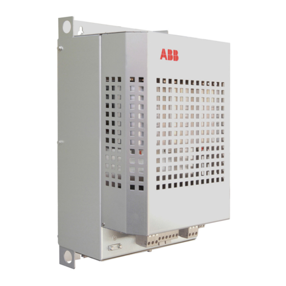
Summary of Contents for ABB ACx580-01 Series
- Page 1 — ABB LV AC DRIVE User Manual for PIHF Harmonic Filters Applicable to ACS510/ACS530 ACx580-01/04 ACS880-01/04...
- Page 2 3AUA0000078093 3AXD50000009104 ACS880-04 Hardware Manual 3AUA0000128301 3AXD50000023005 ACS880 Primary Control Program Firmware Manual 3AUA0000085967 3AXD50000009105 Tools and Maintenance Manual Drive composer PC Tool User Manual 3AUA0000094606 @ 2021 ABB Beijing Drive Systems Co., Ltd 3ABD00045569 Rev D Effective Date: 2021-02-01...
-
Page 3: Table Of Contents
Providing feedback on ABB Drives manuals ........ - Page 4 4 Table of Contents...
-
Page 5: Safety Instructions
Safety Instructions 5 Safety Instructions Contents The safety instructions necessary to the installation, operation and maintenance of harmonic filter units are described in this chapter. Ignoring these safety instructions may result in personal injury or damage to filters, drives, motors or other drive equipment. Please read this chapter carefully before operating the filter. - Page 6 6 Safety Instructions Safety instructions for harmonic filters 1. PIHF harmonic filter is matched with the frequency converter, which can only be mounted at the power inlet of the frequency converter. 2. The power of the selected filter shall be matched with that of the frequency converter as far as possible, to obtain the best filtering effect.
-
Page 7: Guide On Installation And Debugging Of Filters
Guide on Installation and Debugging of Filters 7 Guide on Installation and Debugging of Filters Contents The operating principle and structure of the harmonic filter are briefly described in this chapter. Product overview Wiring diagram The harmonic filter is a low-pass filter that suppresses high-frequency harmonic currents on the input side of the drive. - Page 8 8 Guide on Installation and Debugging of Filters Wiring diagram of single filter (1.5-250kW)
- Page 9 Guide on Installation and Debugging of Filters 9 Wiring diagram of parallel filters (250-400kW) The input terminals (U1,V1,W1) of the parallel filter are all connected to the power supply side, and the output terminals (U2,V2,W2) are all connected to the incoming line side of the frequency converter.
- Page 10 10 Guide on Installation and Debugging of Filters Electrical diagram The figure below shows the electrical diagram of harmonic filters. Model label PIHF-xxxx-x-xx Harmonic content: 10=10% Rated voltage: 4=400V Rated current: 0004=4A Product: PIHF harmonic filter...
-
Page 11: Mechanical Installation
Guide on Installation and Debugging of Filters 11 Mechanical installation The protection degree of PIHF harmonic filter is IP00. The filter shall be installed in a suitable housing or cabinet to ensure safety. The filter adopts natural cooling. Please keep a heat dissipation space of at least 150mm around the filter. -
Page 12: Electrical Connection
12 Guide on Installation and Debugging of Filters Electrical connection S1...S4 Terminal No. Description U1/V1/W1 PIHF filter input terminal U2/V2/W2 PIHF filter output terminal PIHF filter loop control terminal (external contactor A1/B1/C1/A2/B2/C2 control) T1/T2 Overheat protection switch terminal Protective earthing S5...S6 ... - Page 13 Guide on Installation and Debugging of Filters 13 Typical power cable specifications (copper) and wiring torque Incoming and Capacitor outgoing line Temperature switching terminal Harmonic filter terminal control terminal model A1/B1/C1 U1/V1/W1 T1/T2 A2/B2/C2 U2/V2/W2 PIHF-0004-4-10 1.5mm2 1.5mm2 1.5mm2 PIHF-0007-4-10 AWG14 AWG14...
-
Page 14: Model Information
14 Guide on Installation and Debugging of Filters Model information Selection information table ACS510 Frame ACS530 Frame ACx580 Frame ACS880 Frame PIHF- size size size size 3ph 400VAC 02A6 02A7 02A4 0004-4-10 03A3 03A3 03A4 03A3 04A1 04A0 04A1 04A0 05A6 05A6... - Page 15 Guide on Installation and Debugging of Filters 15 Maximum, heat dissipation and noise level Heat Noise Harmonic filter dissipating CFMm3/h filter level model (kW) capacity (CFM) (dB) PIHF-0004-4-10 PIHF-0007-4-10 PIHF-0012-4-10 12.6 PIHF-0015-4-10 PIHF-0030-4-10 PIHF-0045-4-10 PIHF-0075-4-10 PIHF-0090-4-10 PIHF-0160-4-10 343(203) PIHF-0205-4-10 343(203) PIHF-0290-4-10 1050...
-
Page 16: Technical Data
16 Guide on Installation and Debugging of Filters Technical data This chapter describes the technical specifications of the harmonic filter, such as operating conditions, frame size and parameter settings. Power connection Three-phase, U =380 to 415V +10% to -15% Rated voltage Protection class IP00 Under full load conditions, the total harmonic current... - Page 17 Guide on Installation and Debugging of Filters 17 Frame size Weight Model code of Frame size harmonic filter (mm) (mm) (mm) (kg) PIHF-0004-4-10 PIHF-0007-4-10 PIHF-0012-4-10 PIHF-0015-4-10 PIHF-0030-4-10 PIHF-0045-4-10 PIHF-0075-4-10 PIHF-0090-4-10 PIHF-0160-4-10 PIHF-0205-4-10 PIHF-0290-4-10 PIHF-0363-4-10 1060 PIHF-0430-4-10 PIHF-205-4-10 PIHF-290-4-10 Parallel PIHF-0505-4-10 installation PIHF-290-4-10...
- Page 18 18 Guide on Installation and Debugging of Filters Product outline drawing (S1 to S4)
- Page 19 Guide on Installation and Debugging of Filters 19 Product outline drawing (S5,S6)
- Page 20 20 Guide on Installation and Debugging of Filters Parallel Installation Diagram For the model that needs two filters installed in parallel, the wall mounted mode shall be selected, and the installation distance between the filters shall be at least 200mm to ensure a sufficient heat dissipation space. The recommended installation diagram is shown as follows.
-
Page 21: Further Information
Address any inquiries about the product to your local ABB representative, quoting the type designation and serial number of the unit in question. A listing of ABB sales, support and service contacts can be found by navigating to abb.com/search channels. - Page 22 Contact us www.abb.com/drives www.abb.com/drivespartners ABB Beijing Drive Systems Co., Ltd. Beijing 100015, P.R.China, Address: Building 401, No. A-10, Jiuxianqiao Beilu, Chaoyang District, Beijing Tel: +86 10 58217788 Fax: +86 10 58217618 24h × 365d technical hotline: +86 400 810 8885 Website: www.abb.com.cn/drives...


