
Related Manuals for Mitsubishi Electric A173UHCPU


Summary of Contents for Mitsubishi Electric A173UHCPU
- Page 1 Motion Controller User's Manual A173UHCPU, A172SHCPUN, A171SHCPUN Art.-no.: 134383 INDUSTRIAL AUTOMATION 2000 09 01 Version B...
- Page 2 INTORODUCTION Thank you for purchasing the Mitsubishi Motion Controller/A173UHCPU/A172SHCPUN/A171SHCPUN. This instruction manual describes the handing and precautions of this unit. Incorrect handing will lead to unforeseen events, so we ask that you please read this manual thoroughly and use the unit correctly.
- Page 3 For Sate Operations 1. Prevention of electric shocks WARNING Never open the front case or terminal covers while the power is ON or the unit is running, as this may lead to electric shocks. Never run the unit with the front case or terminal cover removed. The high voltage terminal and charged sections will be exposed and may lead to electric shocks.
- Page 4 3. For injury prevention CAUTION Do not apply a voltage other than that specified in the instruction manual on any terminal. Doing so may lead to destruction or damage. Do not mistake the terminal connections, as this may lead to destruction or damage. Do not mistake the polarity (+/-), as this may lead to destruction or damage.
- Page 5 CAUTION Use wires and cables within the length of the range described in the instruction manual. The ratings and characteristics of the system parts (other than control unit, servo amplifier, servomotor) must be compatible with the control unit, servo amplifier and servomotor. Install a cover on the shaft so that the rotary parts of the servomotor are not touched during operation.
- Page 6 (3) Transportation and installation CAUTION Transport the product with the correct method according to the weight. Use the servomotor suspension bolts only for the transportation of the servomotor. Do not transport the servomotor with machine installed on it. Do not stack products past the limit. When transporting the control unit or servo amplifier, never hold the connected wires or cables.
- Page 7 CAUTION When coupling with the synchronization encoder or servomotor shaft end, do not apply impact such as by hitting with a hammer. Doing so may lead to detector damage. Do not apply a load larger than the tolerable load onto the servomotor shaft. Doing so may lead to shaft breakage.
- Page 8 (6) Usage methods CAUTION Immediately turn OFF the power if smoke, abnormal sounds or odors are emitted from the control unit, servo amplifier or servomotor. Always execute a test operation before starting actual operations after the program or parameters have been changed or after maintenance and inspection. The units must be disassembled and repaired by a qualified technician.
- Page 9 (8) Maintenance, inspection and part replacement CAUTION Perform the daily and periodic inspections according to the instruction manual. Perform maintenance and inspection after backing up the program and parameters for the control unit and servo amplifier. Do not place fingers or hands in the clearance when opening or closing any opening. Periodically replace consumable parts such as batteries according to the instruction manual.
- Page 10 This manual confers no industrial property rights or any rights of any other kind, nor does it confer any patent licenses. Mitsubishi Electric Corporation cannot be held responsible for any problems involving industrial property rights which may occur as a result of using the contents noted in this manual.
-
Page 11: Table Of Contents
1.1 Overview of the Motion System ......................1- 1 1.2 Overall Configuration of Motion System .................... 1- 3 1.2.1 A172SHCPUN/A171SHCPUN System Overall Configuration ............ 1- 3 1.2.2 A173UHCPU System Overall Configuration ................1- 5 1.3 Equipment in System ......................... 1- 7 1.4 General Specifications ........................1-10 1.5 Specifications and Settings of Components .................. - Page 12 4.3 Operating System Installation Procedure ..................4- 7 4.4 Trial Run and Adjustment Checklist....................4- 8 5. INSPECTION AND MAINTENANCE ..................5- 1 to 5-23 5.1 Maintenance Works ........................... 5- 1 5.2 Daily Inspections ..........................5- 3 5.3 Scheduled Inspections ........................5- 4 5.3.1 Replacing the Battery ........................
-
Page 13: Specifications Of Motion System Components
• SCPU..Carries out the sequence control, start-up of servo program or motion program, enabling and disabling manual pulse generator operation, and jog operation. Positioning data setting and programming of A173UHCPU/A172SHCPUN/ A171SHCPUN is performed using the following peripheral devices and positioning software package. - Page 14 • The peripheral device started up by the positioning software package can monitor the positioning control conditions of A173UHCPU/A172SHCPUN/ A171SHCPUN, execute the servo program or motion program, and perform a test such as JOG operation.
-
Page 15: Overall Configuration Of Motion System
1. SPECIFICATIONS OF MOTION SYSTEM COMPONENTS 1.2 Overall Configuration of Motion System 1.2.1 A172SHCPUN/A171SHCPUN System Overall Configuration Motion slot Sequence module slot Manual pulse generator/ Extension cable synchronous encoder (A1SC B for interface module A1S6 and A168B) Battery Motion CPU A172 (A1S A6BAT... - Page 16 1. SPECIFICATIONS OF MOTION SYSTEM COMPONENTS CAUTION Configure safety circuits external to the controller or servo amplifier if their abnormal operation could cause axis motion in a direction other than the safe operating direction for the system. Ensure that the characteristics of other components used in a system match those of the controllers, servo amplifiers, and servo motors.
-
Page 17: A173Uhcpu System Overall Configuration
(3) In a motion module, a sequence A1S I/O modules can also be installed. *2 The A173UHCPU can use four channels of the SSCNET. When using the SSCNET card/board (A30CD-PCF/A30BD-PCF), connect it to the SSCNET4 and the servo amplifiers to the SSCNET1 to 3. - Page 18 1. SPECIFICATIONS OF MOTION SYSTEM COMPONENTS CAUTION Configure safety circuits external to the controller or servo amplifier if their abnormal operation could cause axis motion in a direction other than the safe operating direction for the system. Ensure that the characteristics of other components used in a system match those of the controllers, servo amplifiers, and servo motors.
-
Page 19: Equipment In System
1.3 Equipment in System (1) Table of motion modules Current Part Name Model Name Description Consumption Remarks 5 VDC (A) A173UHCPU(-S1) Max. 32 axes control 1.90 CPU module A172SHCPUN Max. 8 axes control 1.63 A171SHCPUN Max. 4 axes control 1.63... - Page 20 1. SPECIFICATIONS OF MOTION SYSTEM COMPONENTS (2) Table of servo amplifier modules Part Name Model Name Description 50 W to 22 kW MR-H Servo amplifier 30 kW to 55 kW MR-H Battery MR-BAT Backup for absolute position detection Termination MR-TM Fitted to the last amplifier of SSCNET connector External regenerative resistor 10 W to 500 W...
- Page 21 1. SPECIFICATIONS OF MOTION SYSTEM COMPONENTS (3) Table of software package (a) Motion function Peripheral Software Package Main OS Software Package Model Name Applicable version Peripheral Teaching Devices function Model Name A173UH A172SH A171SH A172SH/ A173UH A171SH Japanese SW2SRX-GSV13P From 0AC on 00T or later SW2SRX- SW0SRX- SW0SRX-...
-
Page 22: General Specifications
1. SPECIFICATIONS OF MOTION SYSTEM COMPONENTS 1.4 General Specifications Table 1.1 Generation Specifications Item Specification Operating ambient 0 to 55°C temperature Storage ambient -20 to 75°C temperature Operating ambient 10% to 90%RH, no condensation humidity Storage ambient 10% to 90%RH, no condensation humidity Number of Sweeps Frequency... -
Page 23: Specifications And Settings Of Components
1. SPECIFICATIONS OF MOTION SYSTEM COMPONENTS 1.5 Specifications and Settings of Components 1.5.1 A173UHCPU/A172SHCPUN/A171SHCPUN (1) Basic specifications of A173UHCPU, A172SHCPUN and A171SHCPUN Item A173UHCPU(-S1) A172SHCPUN A171SHCPUN No. of control axes 32-axes 8-axes 4-axes 3.5 ms/1 to 20 axes SV13 7.1 ms/21 to 32 axes... - Page 24 1. SPECIFICATIONS OF MOTION SYSTEM COMPONENTS (2) Functions and performance specifications of PCPU The performance specifications and functions of the PCPU depend on the motion function OS model installed in the CPU module. Refer to the programming manual of the motion functions installed in the CPU module.
- Page 25 (a) SCPU performance specifications As the SCPU performance specifications differ according to the operating system used, refer to the appropriate OS Programming Manual for details. Table 1.2 Table of SCPU Performance Specifications Item A173UHCPU(-S1) A172SHCPUN A171SHCPUN Control method Stored programs repeated operation...
- Page 26 *1 Range of positioning dedicated devices differs depending on the OS. Refer to the Programming Manual of each OS. When shared between M, L and S, the total number of devices points is 8192 for the A173UHCPU or 2048 for the A172SHCPUN/A171SHCPUN.
- Page 27 1. SPECIFICATIONS OF MOTION SYSTEM COMPONENTS (b) SCPU functions Refer to the A2SHCPU user's manual for details of the SCPU functions of A171SHCPUN/A172SHCPUN and A3UCPU user’s manual for details of the SCPU functions of A173UHCPU. Table 1.3 Table of SCPU Functions Function Description...
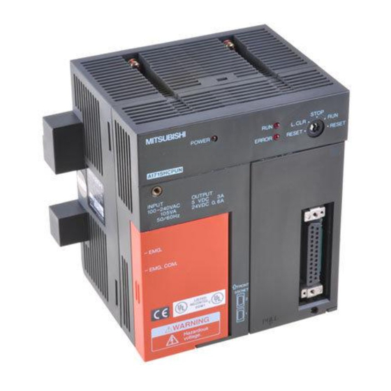
- Page 28 1. SPECIFICATIONS OF MOTION SYSTEM COMPONENTS (4) Names of A173UHCPU/A172SHCPUN/A171SHCPUN Parts A173UHCPU/A172SHCPUN 100 240VAC 100 240VAC 105VA 105VA [A173UHCPU] 18), 19) FRONT SSCNET 1:SSCNET1 2:SSCNET2 3:SSCNET3 4:SSCNET4 A171SHCPUN 100 240VAC 100 240VAC 105VA 24VDC 0.6A 105VA 24VDC 0.6A +24V 18), 19)
- Page 29 (See Section 1.5.1 (5) for details about the switch settings.) ! A connector for connecting the battery unit 17) Battery connector Motion network connector SSCNET1 to 2 (A172SHCPUN/ ! Connectors to HR-H-BN/MR-J2S-B/MR-J2-B. A171SHCPUN) SSCNET1 to 4 (A173UHCPU) 1 − 17...
- Page 30 ! A connector for linking a personal computer and personal computer link SSC. SSCNET2 When using the A172SHCPUN/A171SHCPUN, connect the servo amplifier or (A172SHCPUN/ personal computer to SSCNET2, or when using the A173UHCPU, connect it to A171SHCPUN) SSCNET4. SSCNET4 (A173UHCPU)
- Page 31 * SW402-2 is invalid for A171SHCPUN. * Memory allocation varies depending on the PC memory capacity setting. SW402 For A173UHCPU SCPU built-in RAM memory protect range setting More than 144k bytes Less than a range from 64k to 144k bytes...
- Page 32 1. SPECIFICATIONS OF MOTION SYSTEM COMPONENTS CAUTION Switch SW1-2 is for use by the manufacturer only. Leave this switch set OFF. Operation cannot be guaranteed if this switch is set to ON. POINTS (1) Turn off the power supply before setting the install switch. (2) After using this switch, check the switch status before turning on the power supply.
- Page 33 1. SPECIFICATIONS OF MOTION SYSTEM COMPONENTS (6) Functions and performance specificotions of A173UHCPU/A172SHCPUN/A171SHCPUN internal power supply. Table 1.4 Internal Power Supply Specifications Item Specifications Model name A173UHCPU/A172SHCPUN A171SHCPUN +10% 100 to 240 VAC -15% Input power supply (85 to 264 VAC)
- Page 34 SSC I/F card/board (A30CD-PCF/A30BD-PCF) * : Connect to SSCNET2 for the A171SHCPUN/A172SHCPUN or to SSCNET4 for the A173UHCPU. (8) MELSECNET(II)/10 system The motion system can use the MELSECNET(II)/10 system. The usable MELSECNET system depends on the CPU module. (See the following table.) Load the module given in the following table into the PC slot to configure a data link system.
- Page 35 1. SPECIFICATIONS OF MOTION SYSTEM COMPONENTS (a) MELSECNET(II) Master station Fiber-optic or coaxial cable (64 stations max.) Remote I/O 2nd class Local station station Local station Master station Fiber-optic or coaxial cable Remote I/O 3rd class Local station station Local station POINTS As the instruction for other station access in the MELSECNET(II) data link system, note that the system is not compatible with other station access via...
- Page 36 SSCNET cable Communication cable (A270CDCBL M/A270BDCBL M) SSC I/F card/board (A30CD-PCF/A30BD-PCF) *1: The A31TU-E must be connected with the external circuit. For details, refer to Section 1.5.5 (2). *2: Use SSCNET2 for A171SHCPUN/A172SHCPUN or SSCNET4 for A173UHCPU. 1 − 24...
-
Page 37: Extension Base Power Supply Module
1. SPECIFICATIONS OF MOTION SYSTEM COMPONENTS 1.5.2 Extension Base Power Supply Module (1) Power supply module specifications Table 1.5 Power Supply Module Specifications Specifications Item A1S61PN A1S62PN Mounting position in base Power supply module mounting slot +10% 200 to 240 VAC -15% Input power supply (85 to 264 VAC) - Page 38 1. SPECIFICATIONS OF MOTION SYSTEM COMPONENTS (2) Names of parts (a) A1S61PN power supply module names of parts (FG) (LG) 100-240 VAC Name Application POWER indicator Display indicator for 5 VDC power supply. FG terminal A grounding terminal connected with the shielding pattern on the printed circuit board. LG terminal Ground for power supply filter, with 1/2 the electrical potential of the input voltage.
- Page 39 1. SPECIFICATIONS OF MOTION SYSTEM COMPONENTS (b) A1S62PN power supply module names of parts DC24V 0.6A (FG) (LG) 100-240 VAC Name Application POWER indicator Display indicator for 5 VDC power supply. 24VDC, 24GDC Supplies output modules which require 24 VDC internally (supplied through external terminals wiring).
-
Page 40: Base Units And Extension Cables
1. SPECIFICATIONS OF MOTION SYSTEM COMPONENTS 1.5.3 Base Units and Extension Cables (1) Performance specifications (a) Base unit specifications 1) Main base unit specifications Table 1.6 Table of Main Base Unit Specifications Model Name A178B A178B A178B A172B A175B A178B Item No. - Page 41 1. SPECIFICATIONS OF MOTION SYSTEM COMPONENTS (2) Names and settings of parts (a) Main base unit (A172B, A175B, A178B) Sequencer slot Motion slot Name Application Extension cable Connects to the signal communications connector on the extension base unit with the extension cable.
- Page 42 1. SPECIFICATIONS OF MOTION SYSTEM COMPONENTS (b) Main base unit (A178B-S1/S2/S3) 5) 7) A178B-S2 Motion slot Sequencer slot Name Application Extension cable Connects to the signal communications connector on the extension base unit with the extension cable. connector A cover for protecting the extension cable connector. When connecting to an extension base unit, cut out the area surrounded by the groove under the word “OUT”...
- Page 43 1. SPECIFICATIONS OF MOTION SYSTEM COMPONENTS (c) Extension base unit (A1S65B, A1S68B) A1S68B Name Application Extension cable Connects to the signal communications connector on the main base unit with the extension cable. Remove the connector cover before connecting the extension cable. connector A cover for protecting the extension cable connector.
- Page 44 1. SPECIFICATIONS OF MOTION SYSTEM COMPONENTS (d) Extension base unit (A168B) A168B Name Application Connects to the signal communications connector on the main base unit or bus Extension cable coupling type GOT with the extension cable. connector Take off the supplied connector cover before connecting the extension cable. A cover for protecting the extension cable connector.
- Page 45 5VDC consumed currents of the CPU module, motion modules, MELSEC-A series I/O modules, synchronous encoders and manual pulse generators connected to the main base unit is within 5 (A) for the A173UHCPU/A172SHCPUN or 3 (A) for the A171SHCPUN. 1 − 33...
- Page 46 1. SPECIFICATIONS OF MOTION SYSTEM COMPONENTS (4) Motion slots When using the A172SENC and limit output module (A1SY42), load them into P I/O (motion slots) of the main base. Motion slot (5) Main base unit emergency stop circuit (a) By opening the main base unit emergency stop (EMG) circuit, it is possible to effect an emergency stop all axes of the separate servo amplifiers (MR- H-BN/MR-J2S-B/MR-J2-B) simultaneously.
- Page 47 A1S68B extension base unit POINT 1) Max. number of actual I/O points A173UHCPU:2048 points, A172SHCPUN:1024 points, A171SHCPUN:512 points. The real I/O points can be used within the range of one extension base. 2) When using the bus connection type GOT, use the A168B.
- Page 48 1. SPECIFICATIONS OF MOTION SYSTEM COMPONENTS • Example of using the A175B main base (when a 16-point module is loaded to each slot) Main base unit Motion slot (A175B) Sequencer slot No. 1 2 3 Sequencer slot No. The I/O numbers indicated are those set by automatic I/O assignment.
- Page 49 1. SPECIFICATIONS OF MOTION SYSTEM COMPONENTS • Example of using the A178B-S3 main base (when a 16-point module is loaded to each slot) Sequencer slot No. Motion slot Main base unit (A178B-S3) The I/O numbers indicated are those set by automatic I/O assignment. When empty slots 0 to 7 are set to 0 points (S0) in the I/O assignment, the I/O numbers of slot 8 of the extension...
-
Page 50: Manual Pulse Generator/Synchronous Encoder Interface Module
1. SPECIFICATIONS OF MOTION SYSTEM COMPONENTS 1.5.4 Manual Pulse Generator/Synchronous Encoder Interface Module A172SENC receive external signals required for positioning control (motion control signals and tracking inputs), manual pulse generator inputs, and synchronous encoder inputs. (1) Specifications Table 1.9 A172SENC Specifications Item Specification Model Name... - Page 51 1. SPECIFICATIONS OF MOTION SYSTEM COMPONENTS (2) Description of Parts (a) A172SENC Name Application Display the input status from external equipment and errors detected by self-diagnosis. Description PX0 to Indicators to display the motion control signal input status of each LED indicators PX1F axis.
- Page 52 You can use up to four modules for the A173UHCPU or only one module for the A172SHCPUN or A171SHCPUN. A172SENC Specifications...
- Page 53 CPU modules. CPU Module Manual Pulse Generator Synchronous Encoder A173UHCPU A172SHCPUN/A171SHCPUN 1) Connection of voltage output type and differential output type manual pulse generators and incremental synchronous encoders Use the PULSER connector at the A172SENC module front to connect any of the voltage output type and differential output type manual pulse generators and incremental synchronous encoders.
- Page 54 1. SPECIFICATIONS OF MOTION SYSTEM COMPONENTS • Interface between PULSER connector and voltage-output manual pulse generator/incremental synchronous encoder Pin No. PULSER Input or Connector Wiring Example Internal Circuit Specification Description Signal Name Output Voltage-Output Type • Rated input To connect manual voltage 5.5 VDC pulse generator Manual...
- Page 55 1. SPECIFICATIONS OF MOTION SYSTEM COMPONENTS • Interface between PULSER connector and differential-output manual pulse generator/incremental synchronous encoder Pin No. PULSER Input or Connector Wiring Example Internal Circuit Specification Description Signal Name Output Voltage-Output Type • Rated input To connect manual voltage 5.5 VDC pulse generator Manual...
- Page 56 3) Interface with external equipment The interface between the SY.ENC connector and external equipment is described below. (a) Wiring precautions 1) Tighten the screws after connecting the connector. : A173UHCPU/A172SHCPUN/A171SHCPUN A172S A172SENC : Manual pulse generator/ synchronous encoder interface module SY.SNC...
- Page 57 1. SPECIFICATIONS OF MOTION SYSTEM COMPONENTS CAUTION Connect the SY.ENC connector to external equipment using a shielded cable. To reduce electromagnetic interference, do not position the cable close to, or bundle it with, power or main circuit cables. A clearance of at least 200 mm (0.66 inch) to other cables is required. Connect the shield wire of the shielded cable to the FG terminal of the external equipment.
- Page 58 1. SPECIFICATIONS OF MOTION SYSTEM COMPONENTS • Interface between SY.ENC connector and external equipment Pin No. Input or Wiring Example Internal Circuit Specification Description Signal Name SY.ENC Output Connector • Transmission method: serial communications Serial synchronous • Position detection encoder method: absolute 7, 8, 16 Input...
- Page 59 1. SPECIFICATIONS OF MOTION SYSTEM COMPONENTS Use the CTRL connector at the A172SENC module front to connect the servo external signals. The pin layout and connection of the CTRL connector are described below. The following pin layout is the front view as seen from the CTRL connector front of the A172SENC.
- Page 60 PX13, PX17, PX1B, PX1F command 6.8k Input Tracking enable signal input. • Generates TRA signal 6.8k interrupts to A173UHCPU/ A172SHCPUN/ A171SHCPUN. • Starts counter operation. Common terminals for motion control 5VDC to Power B1 B2 signals, external 24VDC signal and TRA.
-
Page 61: Teaching Unit
1. SPECIFICATIONS OF MOTION SYSTEM COMPONENTS 1.5.5 Teaching Unit (1) Names of parts (a) A30TU-E Emergency Invalid Valid Stop MITSUBISHI A30TU-E A30TU-E SV13 *Data *Monitor *PROG *Test Press the mode key. DATA TEST STOP ITEM CLEAR WRITE STEP- STORE STEP+ RETURN SHIFT ERROR... - Page 62 1. SPECIFICATIONS OF MOTION SYSTEM COMPONENTS (b) A31TU-E Valid Invalid Schematic Schematic drawing drawing of of rear panel front panel Emergency Stop MITSUBISHI A31TU-E A31TU-E SV13 *Data *Monitor *PROG *Test Press the mode key. DATA TEST STOP ITEM CLEAR WRITE STEP- STORE STEP+...
- Page 63 1. SPECIFICATIONS OF MOTION SYSTEM COMPONENTS (2) Selection of teaching unit and connection with CPU module (a) Selection of teaching unit There are the A30TU-E and A31TU-E teaching units. Refer to the following table for selection. Selection of Teaching Unit Comparison A30TU-E A31TU-E...
- Page 64 Teaching unit version is marked on the rated name plate at the rear panel of the unit. (4) A30TU-E rated name plate Unit version A30TU-E DATE MITSUBISHI ELECTRIC CORPORATION (5) A31TU-E rated name plate MITSUBISHI TEACHING UNIT MODEL A31TU-E DATE B...
-
Page 65: Sscnet Cables And Termination Resistor And Their Connection Method
1. SPECIFICATIONS OF MOTION SYSTEM COMPONENTS 1.5.6 SSCNET Cables and Termination Resistor and Their Connection Method Motion controller CPU module SSCNET cable overall length 1)+2) 30m(98.36ft.) Servo amplifier Servo amplifier MR-H-BN MR-H-BN MR-J2S-B MR-J2S-B MR-J2-B MR-J2-B Product Model Description MR-HBUS M For connection of CPU and servo amplifier (MR-H-BN) Cable length within... - Page 66 Use the SSCNET to connect the CPU module and servo amplifiers. When using the A172SHCPUN/A171SHCPUN, only one line of SSCNET is available for servo amplifier connection (use SSCNET1). The A173UHCPU can use up to four lines for servo amplifier connection. One line of SSCNET allows connection of up to eight servo amplifies.
- Page 67 1. SPECIFICATIONS OF MOTION SYSTEM COMPONENTS (c) MR-J2S-B/MR-J2-B+MR-H-BN configuration MR-J2S-B MR-J2S-B CPU module /MR-J2-B /MR-J2-B MR-H-BN Termination connector Battery Battery Battery MR-BAT, MR-BAT, MR-BAT, A6BAT A6BAT A6BAT MR-J2S-B CPU module MR-H-BN /MR-J2-B MR-H-BN Termination connector Battery Battery Battery MR-BAT, MR-BAT, MR-BAT, A6BAT A6BAT...
- Page 68 Axis No.s 1 to 32 can be set for the A173UHCPU, 1 to 8 for the A172SHCPUN, and 1 to 4 for the A171SHCPUN. To set the axis No.s, assign the axis No.s to the axis numbers set with the axis selection switches (rotary switch) of the servo amplifiers (Positions 0 to 7 of the rotary switch correspond to d1 to d8 on the system settings screen.
-
Page 69: Battery
1. SPECIFICATIONS OF MOTION SYSTEM COMPONENTS 1.5.7 Battery This section describes the battery specifications and handling precautions. (1) Battery in CPU module (a) Specifications The specifications of the battery for memory back-up are shown in the table below. Table 1.10 Battery Specifications Model Name A6BAT Item... -
Page 70: Design
2. DESIGN 2. DESIGN This chapter provides those who will design and manage the motion system with the procedures and instructions necessary to design the motion system. For the system and parameter settings and programming method of the motion system, refer to the operating and programming manuals. - Page 71 2. DESIGN Design of system to which GOT and personal computer information control have been added Choose the GOT when using the graphic panel to perform equipment status monitoring and equipment operation. Refer to Section 1.5.1(7). Select the personal computer and related software packages when you want to execute the digital oscilloscope functions designed for tuning and timing checking and user-developed software functions (e.g.
- Page 72 2. DESIGN CAUTION Provide appropriate circuits external to the servo system CPU to prevent cases where danger may result from abnormal operation of the overall system in the event of a power supply fault or servo system CPU failure. Mount each controller, servo amplifier, servomotor, and regenerative resistor on a non- flammable material.
-
Page 73: System Design
2. DESIGN 2.2 System Design To exercise motion control and external I/O equipment control, the motion system consists of the CPU module, main base unit and various modules such as the power supply module, pulse generator/synchronous encoder modules and I/O modules. -
Page 74: External Circuit Design
As to the ways to design the external circuits of the motion system, this section explains the method and instructions for designing the power supply and safety circuits, etc. (1) Sample system circuit design for motion control 3-phase 200/220VAC A172SENC A173UHCPU/ A172SHCPUN/ A171SHCPUN 200VAC PX1F 200VAC BRAKE BRAKE EMG. - Page 75 2. DESIGN POINTS (1) *1 : A 100 VAC power supply can also be used as the power supply to the CPU module. (2) *2 : Sequence program Servo alarm/ M9036 M9074 Error detection (3) *3 : It is also possible to use a full wave rectified power supply as the power supply for the electromagnetic brake.
- Page 76 2. DESIGN (2) Example of system circuit configuration compatible with A31TU-E type teaching unit 3-phase 200/220VAC A173UHCPU/ A172SENC A172SHCPUN/ A171SHCPUN Ym+1 200VAC PX1F 200VAC Ym+n EMG. COM. CPU EMG BRAKE CPU EMGL BRAKE A31TUCBL TU EMG1 TU EMG2 Motion control...
- Page 77 2. DESIGN POINT Outside of control board (1) *1 : 100 VAC power supply can also be used as the power supply to the CPU module. (2) *2 : Sequence program Valid Invalid Schematic drawing of front panel Servo alarm/ Emergency Stop MITSUBISHI A31TU-E...
- Page 78 2. DESIGN (c) Sample system circuit designs Using AC Using AC and DC Power supply Power supply Transformer Transformer Transformer Fuse Fuse Fuse M9006 DC power supply DC power M9006 established signal input M9039 supply M9039 START/STOP circuit M9084 Set TM to time Fuse (Starting possible when the to establish...
-
Page 79: Power Supply Circuit Design
2. DESIGN 2.3.1 Power Supply Circuit Design This section describes the protective coordination and noise suppression techniques of the power supply circuit. (1) Separation and protective coordination (leakage current protection, overcurrent protection) of power supply lines When wiring, separate the lines of CPU module power supplies from those of the I/O equipment and servo amplifier as shown below. - Page 80 2. DESIGN (2) Power supply noise and lightening surge suppression techniques If there is a possibility that a malfunction may occur due to a sneak noise from the main power supply or servo amplifier or due to a lightening surge, use a line noise filter and lightening surge absorber in the power supply lines of the motion controller and I/O equipment.
-
Page 81: Safety Circuit Design
2. DESIGN (4) Grounding The motion system may malfunction as it is affected by various noises such as electric path noises from the power supply lines, radiated and induced noises from other equipment, servo amplifiers and their cables, and electromagnetic noises from conductors. - Page 82 2. DESIGN (2) Main base emergency stop circuit (a) By opening the EMG circuit of the main base unit, all axes of the external servo amplifiers (MR-H-BN/MR-J2S-B/MR-J2-B) can be brought to an emergency stop at once. After an emergency stop, remove the emergency stop factor and cancel the emergency stop (switch on the EMG circuit) to switch on the servo amplifiers immediately.
- Page 83 Servo OFF command Servo error or servo ready OFF detection flag T200 Servo side normal period (200ms) measuring timer Electromagnetic brake operation instruction • For A173UHCPU M2408+20n Turns on M0 when servo error detection (M2408+20n) turns on or servo OFF M3215+20n command (M3215+20n) turns off.
- Page 84 2. DESIGN (4) Failsafe measures for Motion controller failure Failure of the CPU module or memory is detected by the self-diagnosis function, but some abnormalities in the I/O control components cannot be detected by the CPU. Some failures can result in situations such as all points turning on or off, where normal operation and safety of the controlled object cannot be assured.
-
Page 85: Instructions For External Circuit Wiring Design
2. DESIGN 2.3.3 Instructions for External Circuit Wiring Design (1) Wiring (a) Use the wires of the following diameters for wiring. Application Recommended Wire Diameter 100VAC, 200VAC, 24VDC wires Thickest possible wires of 2.0mm max. I/O equipment 0.75mm (0.75 to 1.5mm usable) Ground wire 2.0mm... -
Page 86: Layout Design Within Enclosure
2. DESIGN 2.4 Layout Design within Enclosure 2.4.1 Location Environment Avoid locating the motion controller system in environments subject to: (1) Ambient temperature outside the range 0°C to 55°C (2) Ambient humidity outside the range 10% to 90% RH (3) Condensation resulting from sudden temperature changes (4) Corrosive or inflammable gas (5) Large amounts of conducting dust or iron filings, oil mist, salt, organic solvents (6) Direct sunlight... -
Page 87: Installing The Base Units
2. DESIGN 2.4.2 Installing the Base Units This section describes the precautions related to mounting a motion controller in an enclosure. (1) To improve ventilation and permit easy mounting of the unit, leave a space of at least 30 mm (1.18 inch) between the top of the unit and any other object. (2) Provide a wiring duct, if required. -
Page 88: Installation
2. DESIGN 2.4.3 Installation The mounting positions of the main base unit and extension base unit are shown below. Top of enclosure, wiring duct, or other components Main base unit Extension base unit 30mm (1.18inch) min. Connector for SSCNET 70mm 40mm (1.57inch) (2.76inch) min. -
Page 89: Calculating Heat Generated By A173Uhcpu/A172Shcpun/A171Shcpun
2. DESIGN 2.4.4 Calculating Heat Generated by A173UHCPU/A172SHCPUN/A171SHCPUN If a motion controller is installed in an enclosure, the temperature inside the enclosure must be restricted to the operation ambient temperature of 55 C . The average power consumption (heat generation) of the equipment and instruments in the enclosure must be known to design the heat dissipation of the enclosure. - Page 90 2. DESIGN (4) Average power consumption from voltage drop in output circuits of the output modules (power consumption of simultaneously ON points) Vdrop No. output points Simultaneously ON ratio (W) is the output current(actual operation current) (A) Vdrop: Vdrop is the voltage drop of each output module (V) (5) Average power consumption from voltage drop in input circuits of the input modules (power consumption of simultaneously ON points) E No.
-
Page 91: Design Checklist
2. DESIGN 2.5 Design Checklist At the worksite, copy the following table for use as a check sheet. Item Sub Item Design Confirmation Check Number of axes axes CPU module selection Number of I/O points points Selected CPU module Manual pulse generator pcs. -
Page 92: Mounting And Wiring
3. MOUNTING AND WIRING 3. MOUNTING AND WIRING This chapter provides the mounting and wiring procedures and hardware handling information for those who will mount each equipment to a control box or the like, design wiring and install the hardware. This chapter does not give the ways to install and wire the amplifiers, motors and others and the way to wire the external relay circuit. - Page 93 3. MOUNTING AND WIRING 3.2.1 Mounting without DIN Rail Drill mounting screw holes in accordance with the outline dimensional drawings in Appendix 1.3 Main Base Unit and Appendix 1.4 Extension Base Unit. Screw Tightening Torque Range N 273 to 361 Base mounting screw (M5 screw) (Control box, when screws are made of iron) 3.2.2 Mounting with DIN Rail...
- Page 94 3. MOUNTING AND WIRING (3) Mounting units to, and removing them from, the DIN rail (a) Mounting to DIN rail The procedure to mount a base unit on the DIN rail is described below. 1) Engage the top of the base unit DIN rail groove with the top of the DIN rail.
-
Page 95: Mounting And Removing Modules
3. MOUNTING AND WIRING 3.3 Mounting and Removing Modules This section describes how to mount CPU modules, I/O modules, and special- function modules in a base unit, and how to remove them. (1) Mounting modules Follow the procedure below to mount a module in the base unit. Base unit Module Module... - Page 96 3. MOUNTING AND WIRING (2) Removing modules Follow the procedure below to remove a module from the base unit. Base unit Remove the fixing screws and pivot the module around the bottom lugs toward you. Module connector Lifting the module up, detach the lugs from the module fixing holes.
- Page 97 3. MOUNTING AND WIRING CAUTION When removing a module, remove the module fixing screws before attempting to remove the lugs from module fixing holes. Forcing out a module may damage the lugs. Turn off the power supply before mounting or removing a module. The terminal block and pin connectors of this base unit are made of resin.
-
Page 98: Mounting The Serial Absolute Synchronous Encoder
3. MOUNTING AND WIRING 3.4 Mounting the Serial Absolute Synchronous Encoder Precautions when using a MR-HENC serial absolute synchronous encoder. (1) If the serial absolute synchronous encoder is linked to a chain, timing belt, or gears, the machine rotating shaft should be supported by a separate bearing and connected to MR-HENC through a coupling. - Page 99 3. MOUNTING AND WIRING CAUTION The MR-HENC contains a glass disk and precision mechanism. Take care when handling it. The encoder performance may deteriorate if it is dropped or subjected to shocks or vibration exceeding the prescribed limits. Do not connect the encoder directly to the rotating machine shaft. Always connect the encoder through a flexible coupling.
-
Page 100: Wiring
3. MOUNTING AND WIRING 3.5 Wiring 3.5.1 How to Run the Power Supply and I/O Wires (1) Precautions when using the A1S62PN power supply module 24 VDC output Do not connect 24 VDC outputs from multiple power supply modules in parallel to supply a single I/O module. - Page 101 (c) Grounding cables to be 2 mm min. Grounding point to be as close as possible to the A173UHCPU/A172SHCPUN/A171SHCPUN and the distance to the grounding point as short as possible. (6) Module terminal block wiring screws Tighten the wiring screws of the module terminal block within the following range.
-
Page 102: Example Of Routing The Power Supply And I/O Wires
3. MOUNTING AND WIRING 3.5.2 Example of Routing the Power Supply and I/O Wires This section shows examples of wiring the main base unit and extension base unit power-supply and ground wires. (A17 B, A178B(-S1/S2/S3)) main base unit CPU module 100/110VAC Fuse Select transformer... -
Page 103: Mounting/Wiring Checklist
3. MOUNTING AND WIRING 3.6 Mounting/Wiring Checklist At the worksite, copy the following table for use as a check sheet. Item Sub Item Mounting/Wiring Confirmation Check Check for loose or distorted mounting. Base unit mounting Check that the mounting screw tightening torque is as specified. Check the unit for damage. -
Page 104: Trial Run And Adjustment
4. TRIAL RUN AND ADJUSTMENT 4. TRIAL RUN AND ADJUSTMENT This chapter describes the checking items and procedures necessary for trial run and adjustment for those who will perform trial run and adjustment of the motion system. 4.1 Checklist before Trial Operation Table 4.1 Checklist before Trial Operation Model Name Check Item... - Page 105 4. TRIAL RUN AND ADJUSTMENT CAUTION Check and adjust the programs and parameters before starting trial operation. Errors in the programs or parameters may cause the machine to make unpredicted movements. Never make very large adjustments as this can make operation unstable. WARNING Do not open the front casing or terminal cover during operation or when power is connected.
-
Page 106: Trial Run And Adjustment Procedure
4. TRIAL RUN AND ADJUSTMENT 4.2 Trial Run and Adjustment Procedure POINTS (1) Make note of motor model names before the motor is installed on a machine. The motor name plate may not be visible after the motor is installed. (2) The machine may make unpredictable movements after a servo amplifier or servomotor is first turned on. - Page 107 4. TRIAL RUN AND ADJUSTMENT CAUTION Do not connect a phase-advancer capacitor, surge absorber, or radio noise filter (FR-BIF option) to the servo amplifier output. Ensure output teminals U, V, W, are correctly connected. Abnomal servomotor operation may result if the teminals are incorrctly connected.
- Page 108 4. TRIAL RUN AND ADJUSTMENT CAUTION If used in systems for which safety [Servo PC Mode] standards apply (such as robot systems), Write positioning data all controllers, servo amplifiers, and Write the created sequence programs and servomotors must meet the prescribed motion programs to CPU module with the safety standads.
- Page 109 4. TRIAL RUN AND ADJUSTMENT CAUTION [Test Mode JOG Operation Design system with sufficient mechanical and Manual Pulse Generator] allowance for a safe stop if an axis passes Check machine movements the stroke limit switch at maximum speed. (1) Check the following machine movements using JOG operation from a peripheral device or manual pulse generator operation.
-
Page 110: Operating System Installation Procedure
4. TRIAL RUN AND ADJUSTMENT 4.3 Operating System Installation Procedure In the CPU module, the operating system (hereafter abbreviated to the OS) can be changed using the peripheral device and software package. This OS change is called installation. Start installation Refer to Section 1.5.1(4) for Open the cover at the front of the the information on the install switch. -
Page 111: Trial Run And Adjustment Checklist
4. TRIAL RUN AND ADJUSTMENT 4.4 Trial Run and Adjustment Checklist At the worksite, copy the following table for use as a check sheet. Work Step Item Trial Run and Adjustment Confirmation Check Check that each module is mounted properly. Check that each connector is fitted properly. -
Page 112: Inspection And Maintenance
5. INSPECTION AND MAINTENANCE 5. INSPECTION AND MAINTENANCE This chapter describes the methods of troubleshooting and daily maintenance and inspection for those who will carry out such works. 5.1 Maintenance Works This section explains the periodic and daily inspections performed to operate the motion system safely and normally and the actions to be taken for troubles that may take place during motion system operation. - Page 113 5. INSPECTION AND MAINTENANCE CAUTION Perform daily and periodic inspections in accordance with the directions in this manual and the instruction manual for the product used. Make backups of controller and servo amplifier programs and parameters before carrying out maintenance and inspection. Be careful not to trap your fingers in the gaps when opening and closing parts that can be opened and closed.
-
Page 114: Daily Inspections
5. INSPECTION AND MAINTENANCE 5.2 Daily Inspections The inspections listed in the table below should be conducted every day. Table 5.2 Daily Inspections Item Description Evaluation Standard Remedy All screws tight and covers in Tighten loose Base unit installation Must be firmly installed. position. -
Page 115: Scheduled Inspections
5. INSPECTION AND MAINTENANCE 5.3 Scheduled Inspections The inspections listed in the table below should be conducted once or twice every 6 to 12 months. They should also be conducted after equipment is moved or upgraded, and if the wiring is changed. Table 5.3 Scheduled Inspections Item Description... -
Page 116: Replacing The Battery
5. INSPECTION AND MAINTENANCE 5.3.1 Replacing the Battery (1) Replacing the CPU module battery M9006 or M9007 turns ON if the voltage drops from the A6BAT battery which backs up programs and provides memory back-up functions. Program and memory contents are not lost immediately when these special relays turn ON, but memory contents may be lost if this special realy status is overlooked. - Page 117 5. INSPECTION AND MAINTENANCE (b) Replacing a battery Follow the procedure below to replace a battery when its life expires. After the battery is disconnected, a capacitor maintains memory back-up for a short time. Complete the battery change operation within the time specified in Table 5.5 or the memory contents may be lost.
-
Page 118: Troubleshooting
5. INSPECTION AND MAINTENANCE 5.4 Troubleshooting This section describes the errors which could occur when using the system and what to do about them. Refer to the appropriate software package operating manual for information on the error messages displayed during peripheral device operation. When an error occurs, the system status can be determined by checking the equipment where the error occurred, from the error codes, or by monitoring with a peripheral device. - Page 119 5. INSPECTION AND MAINTENANCE (3) Checking by monitoring from the peripheral device Use the peripheral device monitor functions to determine the control status. The following statuses can be determined. Refer to the appropriate peripheral software package operating manual for details about the operating procedures. (a) Present value monitor Displays servomotor present value addresses and error codes.
-
Page 120: Troubleshooting For Cpu Module And I/O Modules
5. INSPECTION AND MAINTENANCE 5.4.1 Troubleshooting for CPU Module and I/O Modules This section explains how to determine the cause of problems occurring in the SCPU of CPU module or I/O modules, and gives descriptions and remedies the errors indicated by each error code. This manual does not give troubleshooting flowcharts that apply to the use of MR-H-BN, MR-J2S-B and MR-J2-B servo amplifiers. - Page 121 5. INSPECTION AND MAINTENANCE (2) Flowchart when POWER indicator is not lit Follow the flowchart below if the POWER indicator does not light when the power is turned on or goes out during operation. POWER indicator not lit Is power supplied? Supply power.
- Page 122 5. INSPECTION AND MAINTENANCE (3) Flowchart when RUN indicator is not lit Follow the flowchart below if the RUN indicator goes out during operation. RUN indicator goes out Is an error displayed Refer to error table. when a peripheral device is connected? RUN indicator (1) Defective CPU module...
- Page 123 5. INSPECTION AND MAINTENANCE (4) Flowchart when RUN indicator is flashing Follow the flowchart below if the RUN indicator flashes when the power is turned on or during operation. RUN indicator flashing Check error from peripheral Hardware defect device (See Section 5.4.1(10).) Contact your nearest Mitsubishi representative with Reset with the CPU module...
- Page 124 5. INSPECTION AND MAINTENANCE (5) Flowchart when ERROR indicator is lit Follow the flowchart below if the ERROR indicator lights during operation. ERROR indicator lit Connect a peripheral device Is M9008 ON? Cause of error of PCPU? Hardware error Refer to error code table for Cause of error of SCPU? corrective action.
- Page 125 5. INSPECTION AND MAINTENANCE (6) Flowchart when ERROR indicator is flashing Follow the flowchart below if the ERROR indicator flashes during operation. ERROR indicator flashing Does YES (0) special register D9124 contain 0? Contact your nearest NO (not 0) Mitsubishi representative with Reset the coil of the details.
- Page 126 5. INSPECTION AND MAINTENANCE (7) Flowchart when output module load does not turn on Follow the flowchart below if the output module loads do not turn on during operation. Output load does not turn on Is the Check output mode in monitor indicator LED of the output mode from peripheral device.
- Page 127 5. INSPECTION AND MAINTENANCE (8) Flowchart when program cannot be written The following flowchart assumes that a program or other data cannot be written to the CPU when an attempt was made to write it. Program cannot be written Is the Set RUN/STOP switch to RUN/STOP switch set to STOP.
- Page 128 5. INSPECTION AND MAINTENANCE (9) Possible Problems with I/O Modules This section describes possible problems with input and output circuits, and what to do about them. (a) Troubleshooting input circuits Table 5.7 describes problems and corrective actions for input circuits. Table 5.7 Troubleshooting Input Circuits Symptom Cause...
- Page 129 5. INSPECTION AND MAINTENANCE Table 5.7 Troubleshooting Input Circuits (cont.) Symptom Cause Corrective Action • Sneak path due to use of two power supplies. • Use a single power supply. • Connect a diode to prevent sneak paths, as shown in the diagram. Input module Input signal does not turn OFF...
- Page 130 5. INSPECTION AND MAINTENANCE (b) Troubleshooting output circuits Table 5.8 describes problems and corrective actions for output circuits. Table 5.8 Troubleshooting Output Circuits Symptom Cause Corrective Action • If load is internally half-wave rectified • Connect a resistor between several tens k (some solenoids are like this) and several hundreds k across the load.
- Page 131 5. INSPECTION AND MAINTENANCE (10) Table of Error Codes of SCPU If an error occurs when RUN is executed or during CPU module operation, the self- diagnosis function displays an error or stores an error code (including step number) in the special registers. Table 5.9 shows the methods for reading the error codes when an error occurs and describes how to check and correct the error.
- Page 132 5. INSPECTION AND MAINTENANCE Table 5.9 Table of Error Codes (cont.) Contents (BIN) Error of Special Error Description and Cause Corrective Action Status Register D9008 (1) A CHK instruction ladder block (1) Check the CHK instruction contains an instruction (including ladder block for items (1) to (7) NOP) other than LDX, LDIX, in the column to the left.
- Page 133 5. INSPECTION AND MAINTENANCE Table 5.9 Table of Error Codes (cont.) Contents (BIN) Error of Special Error Description and Cause Corrective Action Status Register D9008 (1) During execution, the END code (1) Reset the CPU and run again. was read as a different instruction If the same error is displayed code due to noise, or some other again, a problem exists in the...
- Page 134 A171SHCPUN/A172SHCPUN CPU module, or seven or more or to six or less for computer link modules are loaded A173UHCPU. for one A173UHCPU CPU (2) Reduce A1SJ71AP21/R21 or module. A1SJ71T21B to one or less for (2) Two or more A1SJ71AP21/R21s A171SHCPUN/A172SHCPUN...
-
Page 135: Appendices
APPENDICES APPENDICES Appendix 1 Cables Appendix 1.1 SSCNET Cables Generally use the SSCNET cables of our options. If the length you need is not found in our options, fabricate the cable on the customer side. (1) Selection The following table indicates the SSCNET cables used with the servo amplifiers. - Page 136 APPENDICES (2) MR-HBUS M (a) Explanation of type Type: MR-HBUS M Symbol Cable Length [m] (b) Connection diagram When fabricating a cable, use the recommended wire given on Appendix 1.1 (1), and make the cable as shown in the following connection diagram. The overall distance of the SSCNET cables on the same bus is 30m.
- Page 137 APPENDICES (3) MR-J2HBUS M-A (a) Explanation of type Type: MR-J2HBUS M-A Symbol Cable Length [m] (b) Connection diagram When fabricating a cable, use the recommended wire given on Appendix 1.1 (1), and make the cable as shown in the following connection diagram. The overall distance of the SSCNET cables on the same bus is 30m.
- Page 138 APPENDICES (4) MR-J2HBUS M (a) Explanation of type Type: MR-J2HBUS M Symbol Cable Length [m] (b) Connection diagram When fabricating a cable, use the recommended wire given on Appendix 1.1 (1), and make the cable as shown in the following connection diagram. The overall distance of the SSCNET cables on the same bus is 30m.
-
Page 139: Appendix 1.2 Encoder Cables
APPENDICES Appendix 1.2 Encoder Cables Generally use the encoder cables of our options. If the length you need is not found in our options, fabricate the cable on the customer side. (1) Selection The following table indicates the encoder cables used with the servo motors. Make selection according to your operating conditions. - Page 140 APPENDICES Characteristics of One Core Core Size Finish OD Structure Conductor Insulating Wire Model Number of Cores [mm] [Number of resistance sheath OD wires/mm] /km] d[mm] UL20276 AWG#28 7 pairs (BLAC) 0.08 14 (7 pairs) 7/0.127 222 max. 0.38 UL20276 AWG#28 4 pairs (BLAC) 0.08 8 (4 pairs) 7/0.127...
- Page 141 APPENDICES (2) MR-HSCBL M (Long flexing life product) (a) Explanation of type Type: MR-HSCBL M Symbol Cable Length [m] (b) Connection diagram When fabricating a cable, use the recommended wire and encoder cable fabricating connector set given on Appendix 1.2 (1), and make the cable as shown in the following connection diagram.
- Page 142 APPENDICES (3) MR-EN1CBL M-H (Long flexing life product) (a) Explanation of type Type: MR-EN1CBL M-H Symbol Cable Length [m] (b) Connection diagram When fabricating a cable, use the recommended wire and encoder cable fabricating connector set given on Appendix 1.2 (1), and make the cable as shown in the following connection diagram.
- Page 143 APPENDICES (4) MR-JHSCBL M-L/MR-JHSCBL M-H (a) Explanation of type Type: MR-JHSCBL M- Symbol Specifications Symbol Cable Length [m] Standard flexing life Long flexing life (b) Connection diagram When fabricating a cable, use the recommended wire and encoder cable fabricating connector set given on Appendix 1.2 (1), and make the cable as shown in the following connection diagram.
- Page 144 APPENDICES (5) MR-ENCBL M-H (Long flexing life product) (a) Explanation of type Type: MR-ENCBL M-H Long flexing life Symbol Cable Length [m] (b) Connection diagram When fabricating a cable, use the recommended wire and encoder cable fabricating connector set given on Appendix 1.2 (1), and make the cable as shown in the following connection diagram.
- Page 145 APPENDICES (6) MR-JCCBL M-L/MR-JCCBL M-H (a) Explanation of type Type: MR-JCCBL M- Symbol Specifications Symbol Cable Length [m] Standard flexing life Long flexing life (b) Connection diagram When fabricating a cable, use the recommended wire and encoder cable fabricating connector set given on Appendix 1.2 (1), and make the cable as shown in the following connection diagram.
-
Page 146: Appendix 1.3 A31Tu-E Teaching Unit Cable
APPENDICES Appendix 1.3 A31TU-E Teaching Unit Cable (1) A31TUCBL03M cable (a) A31TUCBL03M cable appearance EMG1 EMG2 DED1 EMGL DED2 (Solderless terminal 0.5-3) CPU module side A31TU-E side (b) A31TUCBL03M cable connection details Pin No. Pin No. Signal name Signal name (Red) (Red) EMG1... - Page 147 APPENDICES (2) A31SHORTCON short-circuit connector (a) A31SHORTCON appearance (b) A31SHORTCON internal wiring Pin No. Signal name EMG1 EMG2 DED1 DED2 Connector 17JE-23250-02(D8A) Manufactured by JAE APP − 13...
-
Page 148: Appendix 2 Outside Dimensions
APPENDICES Appendix 2 Outside Dimensions Appendix 2.1 CPU Modules (1) A173UHCPU Module INPUT OUTPUT 100 - 240VAC 5VDC 5A 105VA 50 / 60Hz WARNING Hazardous voltage (3.69) (4.46) (0.25) (0.66) Unit=mm (inch) (2) A172SHCPUN Module INPUT OUTPUT 100 - 240VAC... - Page 149 APPENDICES (3) A171SHCPUN Module INPUT OUTPUT 100 - 240VAC 5VDC 105VA 24VDC 0.6A 50 / 60Hz WARNING Hazardous voltage (3.69) (4.46) (0.25) (0.66) Unit=mm (inch) APP − 15...
-
Page 150: Appendix 2.2 Pulse Generator/Synchronous Encoder Interface Module (A172Senc)
APPENDICES Appendix 2.2 Pulse Generator/Synchronous Encoder Interface Module (A172SENC) (2.82) 71.6 (1.36) 34.5 (0.87) 93.6 (3.69) (0.91) Unit=mm (inch) (0.26) APP − 16... -
Page 151: Appendix 2.3 Main Base Unit
APPENDICES Appendix 2.3 Main Base Unit (1) A172B main base unit mounting screws 16.4 200(7.87) (0.65) 220(8.66) (1.1) Unit = mm(inch) (2) A175B main base unit mounting screws 16.4 305(12.02) (0.65) 325(12.81) (1.1) Unit = mm(inch) APP − 17... - Page 152 APPENDICES (3) A178B(-S1/S2/S3) main base unit mounting screws A178B 16.4 410(16.15) (0.65) 430(16.94) (1.1) Unit = mm(inch) APP − 18...
-
Page 153: Appendix 2.4 Extension Base Units
APPENDICES Appendix 2.4 Extension Base Units (1) A1S65B extension base unit mounting screws 16.4 295(11.61) (0.65) 315(12.4) (1.1) Unit = mm(inch) (2) A1S68B extension base unit mounting screws 16.4 400(15.75) (0.65) 420(16.54) (1.1) Unit = mm(inch) APP − 19... - Page 154 APPENDICES (3) A168B extension base unit mounting screws 400(15.75) 16.4 (0.65) 420(16.54) (1.1) Unit = mm(inch) APP − 20...
-
Page 155: Appendix 2.5 Teaching Unit
APPENDICES Appendix 2.5 Teaching Unit (1) A30TU-E teaching unit Emergency Invalid Valid Stop MITSUBISHI A 3 0 T U -E DATA TEST STOP ITEM CLEAR WRITE STEP- STORE STEP+ RETURN SHIFT ERROR RESET AXIS JOG - JOG + 95(3.74) 5000(197) Unit = mm(inch) APP −... - Page 156 APPENDICES (2) A31TU-E Teaching Unit 95(3.74) DATA TEST STOP ITEM CLEAR WRITE STEP- STORE STEP+ RETURN SHIFT ERROR RESET AXIS JOG - JOG + Unit = mm(inch) APP − 22...
-
Page 157: Appendix 2.6 Connector
APPENDICES Appendix 2.6 Connector (1) Honda Tsushin Kogyo make PCR-LS20LA1 PCR-LS20LA1 13.0 (0.51) 10.4 (0.41) 14.2 (0.56) 23.0 12.2 (0.91) (0.04) (0.48) (0.04) 27.4 27.4 12.2 (1.08) (1.08) (0.04) (0.48) (0.04) 32.0 32.0 (1.26) (1.26) (0.07) Unit: mm (inch) Type Number of Pins Connector Case... - Page 158 APPENDICES (b) Threaded type Type Connector : 10120-3000VE Shell kit : 10320-52A0-008 • These are not options and should be prepared by the user. 12.0 (0.47) 14.0 (0.55) 22.0 27.4 (1.08) (0.86) 33.3 12.7 Unit: mm (inch) (1.3) (0.5) (c) Insulation displacement type Type Connector : 10120-6000EL Shell kit : 10320-3210-000...
-
Page 159: Appendix 2.7 Manual Pulse Generator Specifications
APPENDICES Appendix 2.7 Manual Pulse Generator Specifications 3.6(0.14) studs (M4 10), Packing, t=2.0 PCD72, equi-spaced +5 to 12V 0V ± 0.5 27.0 8.89 (0.63) (0.79) (1.06) (0.35) (0.3) 4.8(0 to 19)dia., equi-spaced Unit = mm (inch) The figure of processing a disc Item Specification Model name... -
Page 160: Appendix 2.8 Serial Absolute Synchronous Encoder Specifications
APPENDICES Appendix 2.8 Serial Absolute Synchronous Encoder Specifications 68(2.68) 56(2.2) 1.15(0.05) +0.14 2(0.08) 91(3.58) +0.14 1.15(0.05) 4- 5.4(0.21) 20(0.79) Effective dimension 28(1.1) 2(0.08) 19.5 -0.012 21(0.83) 5(0.2) 5(0.2) 3(0.12) (0.77) -0.042 102(4.02) 33(1.3) 135(5.31) Shaft cross-section Cross-section B-B Keyway Dimensional Diagram Unit = mm (inch) Item Specification... - Page 161 MITSUBISHI ELECTRIC CORPORATION HEAD OFFICE:MITSUBISHI DENKI BLDG MARUNOUCHI TOKYO 100 TELEX: J24532 CABLE MELCO TOKYO NAGOYA WORKS : 1-14 , YADA-MINAMI 5 , HIGASHI-KU , NAGOYA , JAPAN IB (NA) 67395-C (0009) MEE Printed in Japan Specifications subject to change without notice.