
Related Manuals for Mitsubishi Electric AJ65BT-68TD


Summary of Contents for Mitsubishi Electric AJ65BT-68TD
- Page 1 AJ65BT-68TD Thermocouple Temperature Input Module User's Manual Downloaded from ManualsNet.com search engine...
- Page 2 Downloaded from ManualsNet.com search engine...
- Page 3 SAFETY PRECAUTIONS (Read these precautions before using this product.) Before using this product, please read this manual and the relevant manuals carefully and pay full attention to safety to handle the product correctly. These precautions apply only to Mitsubishi equipment. Refer to the CPU module user's manual for a description of the programmable controller system safety precautions.
- Page 4 [Installation Precautions] CAUTION Use the programmable controller in an environment that meets the general specifications in this manual. Failure to do so may result in electric shock, fire, malfunction, or damage to or deterioration of the product. For protection of the switches, do not remove the cushioning material before installation. Securely fix the module with a DIN rail or mounting screws.
- Page 5 [Wiring Precautions] CAUTION Place the cables in a duct or clamp them. If not, dangling cable may swing or inadvertently be pulled, resulting in damage to the module or cables or malfunction due to poor contact. Do not install the control lines or communication cables together with the main circuit lines or power cables. Failure to do so may result in malfunction due to noise.
- Page 6 CONDITIONS OF USE FOR THE PRODUCT (1) Mitsubishi programmable controller ("the PRODUCT") shall be used in conditions; i) where any problem, fault or failure occurring in the PRODUCT, if any, shall not lead to any major or serious accident; and ii) where the backup and fail-safe function are systematically or automatically provided outside of the PRODUCT for the case of any problem, fault or failure occurring in the PRODUCT.
- Page 7 Japanese Manual Version SH-3651-F This manual does not imply guarantee or implementation right for industrial ownership or implementation of other rights. Mitsubishi Electric Corporation is not responsible for industrial ownership problems caused by use of the contents of this manual.
-
Page 8: Table Of Contents
Introduction Thank you for purchasing the Mitsubishi Graphic Operation Terminal. Before using the equipment, please read this manual carefully to develop full familiarity with the functions and performance of the graphic operation terminal you have purchased, so as to ensure correct use. Please forward a copy of this manual to the end user. - Page 9 PROM Error Flag is On........................6- 3 When Detected Temperature Value cannot be Read ..................6- 3 When Detected Temperature Value is Abnormal ..................... 6- 3 When There is a Communication Error between Master Station and AJ65BT-68TD ........6- 4 APPENDIX A-1 to A-28 Appendix 1 Usual Operation Limits and Superheated Operating Limits ..............
- Page 10 About Manuals The following are manuals related to this product. Request for the manuals as needed according to the chart below. Related Manuals Manual No. Manual Name (Type code) CC-Link System Master/Local Module Type AJ61BT11/A1SJ61BT11 User's Manual IB-66721 This manual explains about the system configuration, performance specifications, functions, (13J872) handling, wiring and troubleshooting of AJ61BT11and A1SJ61BT11.
- Page 11 About Generic Terms and Abbreviations Unless otherwise specified, this manual uses the following generic terms and abbreviations to explain the AJ65BT-68TD Thermocouple Input Module. Temperature input module. Generic Term/ Description Abbreviation GX Developer Product name of the software package for the MELSEC programmable controllers.
- Page 12 Information input from a remote device station to the master station in 16-bit unit. Represented as RWr for convenience. Packing List This product consists of the following items. Product name Quantity AJ65BT-68TD thermocouple input module AJ65BT-68TD Thermocouple Temperarure Input Module User’s Manual (Hardware) Downloaded from ManualsNet.com search engine...
-
Page 13: Overview
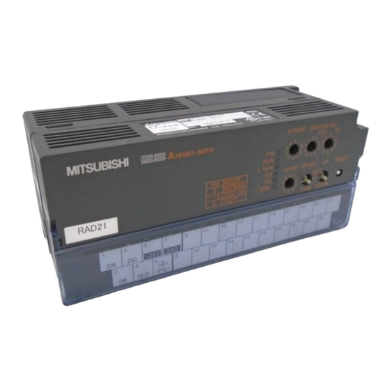
OVERVIEW This user's manual explains the specifications, handling, programming methods, etc. of the AJ65BT- 68TD Thermocouple Input Module (hereinafter referred to as AJ65BT-68TD) used as a remote device station for the CC-Link system. The AJ65BT-68TD is a module that converts the thermocouple input values from outside the programmable controller to the temperature values or scaling values of 16-bit signed BIN data. -
Page 14: System Configuration
SYSTEM CONFIGURATION System configuration when using the AJ65BT-68TD is explained below. Overall Configuration The overall configuration when using the AJ65BT-68TD is shown below. The maximum overall distance for the system is as follows (varies depending on transmission speed setting). 156 kbps : 1200 m (3937 ft.) 5 Mbps : 150 m (492.1 ft.) -
Page 15: Applicable System
2. SYSTEM CONFIGURATION MELSEC-A Applicable System This section explains the applicable system. (1) Applicable master modules For available master modules, visit the CC-Link Partner Association (CLPA) website at: http://www.cc-link.org/ REMARK Check the specifications of the master module before use (2) Restrictions on use of CC-Link dedicated instructions (RLPA, RRPA) The CC-Link dedicated instructions may not be used depending on the programmable controller CPU and master module used. -
Page 16: Specifications
3. SPECIFICATIONS MELSEC-A SPECIFICATIONS This section explains the AJ65BT-68TD the general specifications, performance specifications, and transmission specifications. General Specification This section explains the AJ65BT-68TD general specifications. Item Specifications Ambient operating ° 0 to 55 temperature Ambient storage temperature -20 to 75 °... -
Page 17: Performance Specifications
3. SPECIFICATIONS MELSEC-A Performance Specifications The performance specifications of the AJ65BT-68TD are shown below. Item Specifications Temperature sensor input -200 to 1700 °C Detected 16-bit signed binary (-2000 to 17000 : value to one decimal place multiplied by 10) Output... - Page 18 3. SPECIFICATIONS MELSEC-A Item Specifications CC-Link station type Remote device station Number of occupied stations 4 Stations : RX/RY 128 points each RWw/RWr 16 points each Transmission speed/maximum Refer to Section 3.4 transmission distance Maximum number of 16 modules connected modules Connection cable CC-Link dedicated cable Depends on noise simulator of noise voltage at 500 Vp-p, noise width at 1 ms and noise...
-
Page 19: Temperature/Digital Conversion Characteristics
3. SPECIFICATIONS MELSEC-A Temperature/Digital Conversion Characteristics Since the thermal electromotive force has a non-linear characteristic, it must undergo the linearize processing before being written in the remote register. An example of detected temperature characteristic in respect to the thermocouple input value is shown below. -
Page 20: Data Link Processing Time
3. SPECIFICATIONS MELSEC-A Data Link Processing Time For the AJ65BT-68TD, the data link processing time shown below will be required in order to execute each function. For details on link scan time, refer to the AJ61BT11/A1SJ61BT11 CC-Link System Master/Local Module User's Manual or the AJ61QBT11/A1SJ61QBT11 CC-Link System Master/Local Module User's Manual. -
Page 21: Twisted Cable Specifications
The recommended cable names and specifications are shown in the table below. Item Specification Type FANC–SB 0.5 mm × 3 Mitsubishi Electric System Service, Inc. Contact Kurashige Denkou, Inc. Cable type Twisted shielded cable Conductor cross-sectional area 0.5 mm °... -
Page 22: Function List
3. SPECIFICATIONS MELSEC-A Function List Below is a function list of the AJ65BT-68TD. Item Description Reference section • Detects wire breakage for the connected thermocouple by Wire breakage detection Section 3.8.3 channel. • Performs conversion enable/disable settings by channel. Conversion enable/disable Section 3.8.4... -
Page 23: I/O Signals In Respect To The Master Module
3.8.1 I/O signal list The AJ65BT-68TD uses 128 points for input and 128 points for output in respect to the data for the master module. The I/O signal assignment and the name of each signal are shown in the table below. - Page 24 3. SPECIFICATIONS MELSEC-A Signal direction : AJ65BT-68TD → Master module Signal direction : Master module → AJ65BT-68TD Device No. Signal name Device No. Signal name RX (n+2) 0 CH.1 write data error flag RY (n+2) 0 CH.3 type "K" thermocouple selection flag RX (n+2) 1 CH.2 write data error flag...
- Page 25 3. SPECIFICATIONS MELSEC-A Signal direction : AJ65BT-68TD → Master module Signal direction : Master module → AJ65BT-68TD Device No. Signal name Device No. Signal name RX (n+5) 0 RY (n+5) 0 All CH. batch type "K" thermocouple selection flag RX (n+5) 1 RY (n+5) 1 All CH.
-
Page 26: I/O Signal Functions
3. SPECIFICATIONS MELSEC-A 3.8.2 I/O signal functions The function of each I/O signal for the AJ65BT-68TD is explained below. (1) Input signal Device No. Signal name Description The conversion completion flag turns on when the detected temperature value converted at each channel is stored in the remote register after power on or a hardware reset. - Page 27 3. SPECIFICATIONS MELSEC-A Device No. Signal name Description After power on or a hardware reset, this is turned on because the AJ65BT-68TD Initial data requests the initial data setting . RX (n+7) 8 processing After the initial data processing is complete (initial data processing request flag request flag RY(n+7)8 is turned on), it turns off.
- Page 28 3. SPECIFICATIONS MELSEC-A (2) Output signal Device No. Signal name Description It is possible to designate the conversion enabled or disabled for each channel. By disabling the conversion at channels not in use, generation of unnecessary wire breakage detection flags may be prevented and sampling time may be reduced. ON : Conversion enabled ..
- Page 29 3. SPECIFICATIONS MELSEC-A Device No. Signal name Description Selects the type of thermocouple to be connected to each channel. RY (n+1) 0 CH.1 thermocouple Only the flags appropriate for the thermocouple to be used are turned on. RY (n+1) 6 selection flag It is read as the set value when the initial data processing request flag is turned on.
- Page 30 3. SPECIFICATIONS MELSEC-A Device No. Signal name Description Select whether or not the offset/gain value will be set to "user setting" or "factory setting." At the product shipment from factory, the same values for the factory settings are Offset/gain stored in the E PROM for storing the user setting offset/gain values.
-
Page 31: Wire Breakage Detection
(RXn8 to RXnF) for the corresponding channel. On the AJ65BT-68TD, the wire breakage detection are performed for channels that are enabled for conversion. The relationships between the wire breakage detection and conversion enable/disable are shown below. -
Page 32: Conversion Enable/Disable Designation
(RYn0 to RYn7). Setting Description Wire breakage detection is conducted at the same time the temperature of the target object is taken. Neither temperature detection nor wire breakage detection is conducted. AJ65BT-68TD Remote I/O signal Remote register CH. 1 detected temperature RWrn... -
Page 33: Sampling Processing/Travel Average Processing Designation
3. SPECIFICATIONS MELSEC-A 3.8.5 Sampling processing/travel average processing designation The AJ65BT-68TD may designate sampling processing or travel average processing for each individual channel. The setting of sampling processing or travel average processing is made through the CH. sampling processing/travel average processing designation flags (RYn8 to RYnF). - Page 34 3. SPECIFICATIONS MELSEC-A (2) Sampling processing Stores the detected temperature value and scaling value are stored in the remote register by each sampling time. Sampling time Remote register [°C] 1st storage Detected 2nd storage temperature value 3rd storage Time [ms] The data transition inside the remote register 1st storage 2nd storage...
-
Page 35: Thermocouple Type Selection
MELSEC-A 3.8.6 Thermocouple type selection The AJ65BT-68TD can select the thermocouple to use for individual channels or all channels in batch. (1) When selecting the thermocouple to use for individual channels The CH. "K" to "S" type thermocouple selection flags are used to select the thermocouple used for each channel. -
Page 36: Pt100 Cold Junction Compensation Enable/Disable Designation
MELSEC-A 3.8.7 Pt100 cold junction compensation enable/disable designation The AJ65BT-68TD can designate the enabling/disabling of the cold junction compensation by the Pt100 temperature-measuring resistor. By designating the enabling/disabling of the cold junction compensation by the Pt100 temperature- measuring resistor, the detected temperature value to be stored in the remote register may be switched between the value obtained using the Pt100 temperature-measuring resistor and not using the Pt100 temperature-measuring resistor (when performing cold junction compensation externally). -
Page 37: Remote Register
3. SPECIFICATIONS MELSEC-A Remote Register The AJ65BT-68TD is equipped with remote registers for data communication with the master module. The assignment and data structure of the remote register are explained below. 3.9.1 Remote register assignment The remote register assignments are shown in the table below. -
Page 38: High And Low Limit Settings
3.9.2 High and low limit settings The AJ65BT-68TD can set the measured temperature range (upper and lower limits) for each channel to the remote register (RWwm to RWwm+15) The value of the detected temperature value range for the thermocouple set by the thermocouple selection flag is used by default. -
Page 39: Detected Temperature Value
3.9.3 Detected temperature value The measurable temperature range for the AJ65BT-68TD is between -200 °C and 1700 °C. The temperature read by each channel is converted to a detected temperature value that has undergone the linearize processing and cold junction compensation, and stored to the remote register. -
Page 40: Setting And Procedure Before Operation
4. SETTING AND PROCEDURE BEFORE OPERATION MELSEC-A SETTING AND PROCEDURE BEFORE OPERATION The procedure before operation of AJ65BT-68TD, part identification and setting, and the wiring method are explained below. Procedure before Operation The procedure before operation of AJ65BT-68TD is explained below. -
Page 41: Handling Precautions
4. SETTING AND PROCEDURE BEFORE OPERATION MELSEC-A Handling Precautions The handling precautions for AJ65BT-68TD is explained below. • Securely fix the module with a DIN rail or mounting screws. Tighten the screws CAUTION within the specified torque range. Undertightening can cause drop of the screw, short circuit or malfunction. -
Page 42: Part Identification And Setting
Name Description Station setting Sets the station number of AJ65BT-68TD in the range of 1 to 61. switch " × 10" sets the ten's place for a station number. " × 1" sets the one's place for a station number. - Page 43 ON for more than 1.5 seconds : increase/decrease 0.1 °C per 0.04 seconds. DOWN Reset switch Hardware reset Initialize the remote register and operation processing of AJ65BT-68TD. RESET The initial data processing request flag turns on by turning the switch on. LED for...
-
Page 44: Error Compensation By The Offset Value/Gain Value Setting
SET. • The offset value and gain value are stored inside AJ65BT-68TD and are not erased even at power off. -
Page 45: Initial Settings For Error Compensation
4. SETTING AND PROCEDURE BEFORE OPERATION MELSEC-A 4.4.1 Initial settings for error compensation The following shows the initial settings using a program designed for executing error compensation. Start Create a type designation program for thermocouple Create a program that designates a sampling processing and travel average processing *1 Create a program that reads the detected temperature values... -
Page 46: Error Compensation Procedure
The following shows the flow of error compensation. Start Input a value to be the gain value. Set the mode switch to 9 for test mode. After two seconds, confirm that the RUN LED is AJ65BT-68TD turned off. MODE Turns off 80 [°C]... -
Page 47: Station Number Setting
For details, refer to AJ61BT11/A1SJ61BT11 CC-Link System Master Local Module User's Manual or AJ61QBT11/A1SJ61QBT11 CC-Link System Master Local Module User's Manual. Orientation of Module Installation The following shows the possible orientation for AJ65BT-68TD installation. Panel When installing alongside the panel... -
Page 48: Wiring
Wiring 4.7.1 Wiring example with CC-Link modules The following shows the connection between the AJ65BT-68TD and master module using twisted cables. POINT For the modules at both ends of the data link, make sure to connect the "terminal resistor" that is attached to a master module (connect between DA and DB). -
Page 49: Precautions When Wiring To A Thermocouple
The following describes the external wiring precautions. (1) Use separate cables for the AC and the external input signals of the AJ65BT-68TD, in order not to be affected by the AC side surge or conductivity. -
Page 50: Programming Procedure
5. PROGRAMMING MELSEC-A PROGRAMMING The programming procedure, basic programming for read and write, as well as programming examples are explained below. When utilizing the program examples introduced in this chapter for an actual system, fully verify that controllability in the target system has no problems. Refer to the user's manual (details) of the master module used for the master module, to Section 3.9 for the remote registers, and to the AnSHCPU/AnACPU/AnUCPU/QCPU-A (A mode) programming manual (dedicated Instructions) for details of the dedicated instructions. - Page 51 5. PROGRAMMING MELSEC-A Program Example Conditions The program examples given in this chapter have been created under the following conditions. (1) System configuration Downloaded from ManualsNet.com search engine...
- Page 52 5. PROGRAMMING MELSEC-A (2) Relationships between programmable controller CPU, master module and AJ65BT-68TD POINT Depending on the used CPU module, the devices used in the program examples of this chapter may not be applicable. For the device setting ranges, refer to the user's manual of the used CPU module.
- Page 53 5. PROGRAMMING MELSEC-A (3) Initial setting Setting item Description CH. 1 sampling processing/travel average Travel average processing processing designation flag (RY08) CH. 2 sampling processing/travel average Travel average processing processing designation flag (RY09) All CH. batch “K” type thermocouple “K” type thermocouple for all channels selection flag (RY50) Pt100 cold junction compensation disable Cold junction compensation is performed by...
- Page 54 5. PROGRAMMING MELSEC-A Program Examples when QCPU (Q Mode) Is Used The network parameters and auto refresh parameters have been set by GX Developer. Initial setting can be made easily by using the remote device station initialization procedure registration function. (1) Parameter setting (a) Network parameter setting (b) Auto refresh parameter setting...
- Page 55 Set the target station number of initial setting. Set the target station number to "1". (b) Procedure registration setting The initial setting is registered to the AJ65BT-68TD when the initial data processing request flag (RX78) turns ON and Remote device station initialization procedure registration (SB0D) is set.
- Page 56 5. PROGRAMMING MELSEC-A (c) Setting result The setting result is shown below. Downloaded from ManualsNet.com search engine...
-
Page 57: Program Example Conditicons
5. PROGRAMMING MELSEC-A (3) Program example Downloaded from ManualsNet.com search engine... - Page 58 5. PROGRAMMING MELSEC-A *1: When making remote device station initialization procedure registration to multiple stations, correct the program within the dotted line 1) as shown below. [System configuration] [Corrected program] • RX(m+7)9 and RX(n+7)9 are initial data setting completion flags. •...
- Page 59 5. PROGRAMMING MELSEC-A [Usage in combination with other remote device stations] (1) Depending on the remote device stations to be used, the program enclosed by the dotted line 1) has two programming patterns as shown in the above and the below figures. (To check which pattern can be used, refer to the manual for the remote device to be used.) [System configuration] [Corrected program]...
- Page 60 5. PROGRAMMING MELSEC-A (2) When using the program enclosed by the dotted line 1) in combination with other remote device stations, correct the program as shown below. [System configuration] [Corrected program] Note that the master module can register the initialization procedure of only the specified station out of the multiple remote device stations.
- Page 61 5. PROGRAMMING MELSEC-A * Reading detected temperature/scaling value, detection of out-of-range measurement CH.1温 温温 温 温 Reads CH. 1 detected temperature value (0.1℃ 単単)(RWr0)の (0.1 units) (RWr0). 読温 し CH.1ス ス ス ス ス ス 温 Reads CH. 1 scaling value (RWr8).
-
Page 62: Program Eamples When Qnacpu Is Used
5. PROGRAMMING MELSEC-A Program Examples when QnACPU Is Used The network parameters and auto refresh parameters have been set by GX Developer. (1) Parameter setting (a) Network parameter setting (b) Auto refresh parameter setting 5-13 Downloaded from ManualsNet.com search engine... - Page 63 5. PROGRAMMING MELSEC-A (2) Program example * AJ65BT-68TD status check Reads data link status. デ ス デ ス ス デ 状状の 読温し AJ 65BT-68TD AJ65BT-68TD data デ ス デ ス ス デ 正異 link normal AJ 65BT-68TD AJ65BT-68TD data デ ス デ ス ス デ 異異...
- Page 64 5. PROGRAMMING MELSEC-A * Reading detected temperature/scaling value, detection of out-of-range measurement CH.1温 温温 温 温 Reads CH. 1 detected temperature value (0.1℃ 単単)(RWr0)の (0.1 units) (RWr0). 読温 し CH.1ス ス ス ス ス ス 温 Reads CH. 1 scaling value (RWr8).
- Page 65 The network parameters and auto refresh parameters have been set by the sequence program. (1) Program example Network parameter setting by dedicated instruction RLPA Synchronous mode invalid Number of connected modules: 1 AJ65BT-68TD station information (remote device station, 4 stations occupied, station No. 1) Dedicated instruction...
- Page 66 Master module head I/O No. 先先 I /O 先先 パ エ パ ス デ 格格 Parameter storage head device 先先デ オ ゲ ス AJ65BT-68TD status check Reads data link status. デ ス デ ス ス デ 状状の 確確 AJ 65BT-68TD AJ65BT-68TD data link normal デ...
- Page 67 5. PROGRAMMING MELSEC-A Changing the initial settings Initial setting change ゲ イ イ イ イ 設測変変 CH. 1 sampling processing/ CH . 1 サ ス サ ス ス ス 処処/ travel average processing 移移移移処処移測フ エ ス designation flag (RY08) ( RY08 ) CH.
- Page 68 5. PROGRAMMING MELSEC-A Program Example when ACPU/QCPU (A Mode) Is Used (FROM/TO Instructions) The network parameters have been set by the sequence program. (1) Program example 5-19 Downloaded from ManualsNet.com search engine...
- Page 69 5. PROGRAMMING MELSEC-A Pt 100冷接接補補禁禁 Pt100 cold junction compensation フ エ ス ( RY57) disable flag(RY57) オ フ エ エ エ ・ ゲ ゲ ス 温 Offset/gain value selection 選選フ エ ス ( RY77) flag(RY77) CH . 1下下温( 0. 1℃単単) CH.1 lower limit value (...
- Page 70 5. PROGRAMMING MELSEC-A * Handling at error occurrence Turns ON Y95 when PRO M 異異時Y95を O N E PROM is faulty. Turns ON Y96 when CH . 1断断温温時Y96を O N CH. 1 wire breakage is detected. Turns ON Y97 when CH .
-
Page 71: Troubleshooting
The general troubleshooting methods for using AJ65BT-68TD is explained below. Cause of Errors and Corrective Actions by LED Indication The following describes the error confirmation method using the LEDs on AJ65BT-68TD. For the errors associated with the programmable controller CPU and master module, refer to the user's manual for the programmable controller CPU and master module, respectively. - Page 72 6. TROUBLESHOOTING MELSEC-A (4) When AJ65BT-68TD's "L RUN" LED is off Cause Corrective action Look for the broken or shorted transmission cables and repair Cables are broken or shorted. them. The master station has the stopped data link. Confirm that no error has occurred in the master station.
-
Page 73: When Wire Breakage Detection Flag Is On
When E PROM Error Flag is On Cause Corrective action Restart power for AJ65BT-68TD. *1 Error in the internal memory storing the offset If the E PROM error flag is still on after power restart, contact value/gain value set by user the nearest representative or branch regarding the problem, as hardware may be faulty. -
Page 74: When There Is A Communication Error Between Master Station And Aj65Bt-68Td
AJ65BT-68TD If the station number duplicate bit is turned on in the link special register SW0098 to SW009B (duplicate station number status), check the corresponding station number of AJ65BT-68TD using the following flow. Troubleshooting flow when "ERR" LED of master station is flickering "ERR."... - Page 75 6. TROUBLESHOOTING MELSEC-A From the previous page From the previous page From the previous page Is "L RUN" LED lit? Is "SD" LED lit (flickering)? Is the baud rate setting correct? Is "SD" LED lit (flickering)? Correct the baud rate setting Corresponding Restart the power supply/ module failure...
-
Page 76: Appendix
APPENDIX MELSEC-A APPENDIX Appendix 1 Usual Operation Limits and Superheated Operating Limits JIS C1602-1995 Component Old symbol Wire diameter Usual operation limit Superheated operating °C limit °C symbol (reference) ⎯ 0.50 1500 1700 ⎯ 0.50 1600 1400 0.65 1.00 1.60 1050 2.30 1100... -
Page 77: Appendix 3 Thermal Electromotive Force Chart
APPENDIX MELSEC-A Appendix 3 Thermal Electromotive Force Chart Type B Appendix 3.1 Standard Thermal Electromotive Force of B Unit μV JIS C1602-1995 (Conform to IEC584-1(1977), IEC 584-2-(1982)) Temperature Temperature (°C) (°C) 1002 1007 1011 1016 1020 1025 1030 1034 1039 1043 1048 1053... - Page 78 APPENDIX MELSEC-A Type B Unit μV JIS C1602-1995 (Conform to IEC584-1(1977), IEC 584-2-(1982)) Temperature Temperature (°C) (°C) 1242 1247 1252 1257 1262 1267 1272 1277 1282 1288 1293 1298 1303 1308 1313 1318 1324 1329 1334 1339 1344 1350 1355 1360 1365 1371...
- Page 79 APPENDIX MELSEC-A Type B Unit μV JIS C1602-1995 (Conform to IEC584-1(1977), IEC 584-2-(1982)) Temperature Temperature (°C) (°C) 1000 4834 4843 4853 4862 4871 4880 4889 4898 4908 4917 1000 1010 4926 4935 4944 4954 4963 4972 4981 4990 5000 5009 1010 1020 5018...
- Page 80 APPENDIX MELSEC-A Type B Unit μV JIS C1602-1995 (Conform to IEC584-1(1977), IEC 584-2-(1982)) Temperature Temperature (°C) (°C) 1500 10099 10111 10122 10134 10145 10157 10168 10180 10192 10203 1500 1510 10215 10226 10238 10249 10261 10273 10284 10296 10307 10319 1510 1520 10331...
-
Page 81: Appendix 3.2 Standard Thermal Electromotive Force Of R
APPENDIX MELSEC-A Appendix 3.2 Standard Thermal Electromotive Force of R Type R Unit μV JIS C1602-1995 (Conform to IEC584-1(1977), IEC 584-2-(1982)) Temperature Temperature (°C) (°C) -226 -188 -192 -196 -200 -204 -208 -211 -215 -219 -223 -145 -150 -154 -158 -163 -167 -171... - Page 82 APPENDIX MELSEC-A Type R Unit μV JIS C1602-1995 (Conform to IEC584-1(1977), IEC 584-2-(1982)) Temperature Temperature (°C) (°C) 3408 3418 3428 3439 3449 3460 3470 3480 3491 3501 3512 3522 3533 3543 3553 3564 3574 3585 3595 3606 3616 3627 3637 3648 3658 3669...
- Page 83 APPENDIX MELSEC-A Type R Unit μV JIS C1602-1995 (Conform to IEC584-1(1977), IEC 584-2-(1982)) Temperature Temperature (°C) (°C) 9205 9218 9230 9243 9256 9269 9282 9294 9307 9320 9333 9346 9359 9371 9384 9397 9410 9423 9436 9449 9461 9474 9487 9500 9513 9526...
- Page 84 APPENDIX MELSEC-A Type R Unit μV JIS C1602-1995 (Conform to IEC584-1(1977), IEC 584-2-(1982)) Temperature Temperature (°C) (°C) 1400 16040 16054 16068 16082 16097 16111 16125 16139 16153 16167 1400 1410 16181 16196 16210 16224 16238 16252 16266 16280 16294 16309 1410 1420 16323...
-
Page 85: Appendix 3.3 Standard Thermal Electromotive Force Of S
APPENDIX MELSEC-A Appendix 3.3 Standard Thermal Electromotive Force of S Type S Unit μV JIS C1602-1995 (Conform to IEC584-1(1977), IEC 584-2-(1982)) Temperature Temperature (°C) (°C) -236 -194 -199 -203 -207 -211 -215 -219 -224 -228 -232 -150 -155 -159 -164 -168 -173 -177... - Page 86 APPENDIX MELSEC-A Type S Unit μV JIS C1602-1995 (Conform to IEC584-1(1977), IEC 584-2-(1982)) Temperature Temperature (°C) (°C) 3259 3269 3279 3288 3298 3307 3317 3326 3336 3346 3355 3365 3374 3384 3394 3403 3413 3423 3432 3442 3451 3461 3471 3480 3490 3500...
- Page 87 APPENDIX MELSEC-A Type S Unit μV JIS C1602-1995 (Conform to IEC584-1(1977), IEC 584-2-(1982)) Temperature Temperature (°C) (°C) 8449 8460 8472 8483 8494 8505 8517 8528 8539 8550 8562 8573 8584 8595 8607 8618 8629 8640 8652 8663 8674 8685 8697 8708 8719 8731...
- Page 88 APPENDIX MELSEC-A Type S Unit μV JIS C1602-1995 (Conform to IEC584-1(1977), IEC 584-2-(1982)) Temperature Temperature (°C) (°C) 1400 14373 14385 14397 14409 14421 14433 14445 14457 14470 14482 1400 1410 14494 14506 14518 14530 14542 14554 14567 14579 14591 14603 1410 1420 14615...
-
Page 89: Appendix 3.4 Standard Thermal Electromotive Force Of K
APPENDIX MELSEC-A Appendix 3.4 Standard Thermal Electromotive Force of K Type K Unit μV JIS C1602-1995 (Conform to IEC584-1(1977), IEC 584-2-(1982)) Temperature Temperature (°C) (°C) -270 -6458 -270 -260 -6441 -6444 -6446 -6448 -6450 -6452 -6453 -6455 -6456 -6457 -260 -250 -6404 -6408... - Page 90 APPENDIX MELSEC-A Type K Unit μV JIS C1602-1995 (Conform to IEC584-1(1977), IEC 584-2-(1982)) Temperature Temperature (°C) (°C) 6138 6179 6219 6259 6299 6339 6380 6420 6460 6500 6540 6580 6620 6660 6701 6741 6781 6821 6861 6901 6941 6981 7021 7060 7100 7140...
- Page 91 APPENDIX MELSEC-A Type K Unit μV JIS C1602-1995 (Conform to IEC584-1(1977), IEC 584-2-(1982)) Temperature Temperature (°C) (°C) 24905 24948 24990 25033 25075 25118 25160 25203 25245 25288 25330 25373 25415 25458 25500 25543 25585 25627 25670 25712 25755 25797 25840 25882 25924 25967...
- Page 92 APPENDIX MELSEC-A Type K Unit μV JIS C1602-1995 (Conform to IEC584-1(1977), IEC 584-2-(1982)) Temperature Temperature (°C) (°C) 1050 43211 43250 43288 43327 43365 43403 43442 43480 43518 43557 1050 1060 43595 43633 43672 43710 43748 43787 43825 43863 43901 43940 1060 1070 43978...
-
Page 93: Appendix 3.5 Standard Thermal Electromotive Force Of E
APPENDIX MELSEC-A Appendix 3.5 Standard Thermal Electromotive Force of E Type E Unit μV JIS C1602-1995 (Conform to IEC584-1(1977), IEC 584-2-(1982)) Temperature Temperature (°C) (°C) -270 -9835 -270 -260 -9797 -9802 -9808 -9813 -9817 -9821 -9825 -9828 -9831 -9833 -260 -250 -9718 -9728... - Page 94 APPENDIX MELSEC-A Type E Unit μV JIS C1602-1995 (Conform to IEC584-1(1977), IEC 584-2-(1982)) Temperature Temperature (°C) (°C) 13421 13495 13569 13644 13718 13792 13866 13941 14015 14090 14164 14239 14313 14388 14463 14537 14612 14687 14762 14837 14912 14987 15062 15137 15212 15287...
- Page 95 APPENDIX MELSEC-A Type E Unit μV JIS C1602-1995 (Conform to IEC584-1(1977), IEC 584-2-(1982)) Temperature Temperature (°C) (°C) 53112 53192 53272 53351 53431 53510 53590 53670 53749 53829 53908 53988 54067 54147 54226 54306 54385 54465 54544 54624 54703 54782 54862 54941 55021 55100...
-
Page 96: Appendix 3.6 Standard Thermal Electromotive Force Of J
APPENDIX MELSEC-A Appendix 3.6 Standard Thermal Electromotive Force of J Type J Unit μV JIS C1602-1995 (Conform to IEC584-1(1977), IEC 584-2-(1982)) Temperature Temperature (°C) (°C) -210 -8095 -210 -200 -7890 -7912 -7934 -7955 -7976 -7996 -8017 -8037 -8057 -8076 -200 -190 -7659 -7683... - Page 97 APPENDIX MELSEC-A Type J Unit μV JIS C1602-1995 (Conform to IEC584-1(1977), IEC 584-2-(1982)) Temperature Temperature (°C) (°C) 10779 10834 10890 10945 11001 11056 11112 11167 11223 11278 11334 11389 11445 11501 11556 11612 11667 11723 11778 11834 11889 11945 12000 12056 12111 12167...
- Page 98 APPENDIX MELSEC-A Type J Unit μV JIS C1602-1995 (Conform to IEC584-1(1977), IEC 584-2-(1982)) Temperature Temperature (°C) (°C) 36071 36131 36191 36252 36312 36373 36433 36494 36554 36615 36675 36736 36797 36858 36918 36979 37040 37101 37162 37223 37284 37345 37406 37467 37528 37590...
- Page 99 APPENDIX MELSEC-A Type J Unit μV JIS C1602-1995 (Conform to IEC584-1(1977), IEC 584-2-(1982)) Temperature Temperature (°C) (°C) 1100 63792 63850 63908 63966 64024 64081 64139 64197 64255 64313 1100 1110 64370 64428 64486 64544 64602 64659 64717 64775 64833 64890 1110 1120 64948...
-
Page 100: Appendix 3.7 Standard Thermal Electromotive Force Of T
APPENDIX MELSEC-A Appendix 3.7 Standard Thermal Electromotive Force of T Type T Unit μV JIS C1602-1995 (Conform to IEC584-1(1977), IEC 584-2-(1982)) Temperature Temperature (°C) (°C) -270 -6258 -270 -260 -6232 -6236 -6239 -6242 -6245 -6248 -6251 -6253 -6255 -6256 -260 -250 -6180 -6187... - Page 101 APPENDIX MELSEC-A Type T Unit μV JIS C1602-1995 (Conform to IEC584-1(1977), IEC 584-2-(1982)) Temperature Temperature (°C) (°C) 9288 9341 9395 9448 9501 9555 9608 9662 9715 9769 9822 9876 9930 9984 10038 10092 10146 10200 10254 10308 10362 10417 10471 10525 10580 10634...
-
Page 102: Appendix 4 External Dimensions Diagram
APPENDIX MELSEC-A Appendix 4 External Dimensions Diagram A-27 Downloaded from ManualsNet.com search engine... - Page 103 APPENDIX MELSEC-A MEMO A-28 Downloaded from ManualsNet.com search engine...
- Page 104 WARRANTY Please confirm the following product warranty details before using this product. 1. Gratis Warranty Term and Gratis Warranty Range If any faults or defects (hereinafter "Failure") found to be the responsibility of Mitsubishi occurs during use of the product within the gratis warranty term, the product shall be repaired at no cost via the sales representative or Mitsubishi Service Company.
- Page 105 Downloaded from ManualsNet.com search engine...
- Page 106 SH(NA)-3304-D(1012)MEE MODEL: AJ65BT-68TD-U-E MODEL CODE: 13JL52 HEAD OFFICE : TOKYO BUILDING, 2-7-3 MARUNOUCHI, CHIYODA-KU, TOKYO 100-8310, JAPAN NAGOYA WORKS : 1-14 , YADA-MINAMI 5-CHOME , HIGASHI-KU, NAGOYA , JAPAN When exported from Japan, this manual does not require application to the Ministry of Economy, Trade and Industry for service transaction permission.