Table of Contents
Advertisement
Thank you for purchasing the Mitsubishi programmable controller
MELSEC-A series.
Prior to use, please read this and relevant manuals thoroughly to
fully understand the product.
© 1997 MITSUBISHI ELECTRIC CORPORATION
High-Speed
Counter Module
AJ65BT-D62D-S1
MODEL AJ65BT-D62-U-H-E
MODEL
CODE
IB(NA)-66822-G(1806)MEE
User's Manual
(Hardware)
AJ65BT-D62
AJ65BT-D62D
13JL44
Advertisement
Table of Contents

Related Manuals for Mitsubishi Electric AJ65BT-D62


Summary of Contents for Mitsubishi Electric AJ65BT-D62
- Page 1 (Hardware) AJ65BT-D62 AJ65BT-D62D AJ65BT-D62D-S1 Thank you for purchasing the Mitsubishi programmable controller MELSEC-A series. Prior to use, please read this and relevant manuals thoroughly to fully understand the product. MODEL AJ65BT-D62-U-H-E MODEL 13JL44 CODE IB(NA)-66822-G(1806)MEE © 1997 MITSUBISHI ELECTRIC CORPORATION...
-
Page 2: Safety Precautions
SAFETY PRECAUTIONS (Read these precautions before using this product.) Before using this product, please read this manual and the relevant manuals carefully and pay full attention to safety to handle the product correctly. In this manual, the safety precautions are classified into two levels: "... -
Page 3: Wiring Precautions
[Design Precautions] CAUTION ● Do not have control cables and communication cables bundled with or placed near by the main circuit and/or power cables. Wire those cables at least 100mm (3.94 inch) away from the main circuit and/or power cables. Not doing so could result in noise that would cause erroneous operation. - Page 4 [Wiring Precautions] CAUTION ● Be sure to ground the FG terminal to the class-3 or higher grounding. Otherwise there will be a danger of malfunctions. ● Use applicable solderless terminals and tighten them with the specified torque. If any solderless spade terminal is used, it may be disconnected when the terminal screw comes loose, resulting in failure.
- Page 5 [Starting and Maintenance Precautions] CAUTION ● Never try to disassemble or modify module. It may cause product failure, malfunction, fire or cause injury. ● Do not drop or apply strong shock to the module case. Failure to do so may damage the module.
- Page 10 CONDITIONS OF USE FOR THE PRODUCT (1) Mitsubishi programmable controller ("the PRODUCT") shall be used in conditions; i) where any problem, fault or failure occurring in the PRODUCT, if any, shall not lead to any major or serious accident; and ii) where the backup and fail-safe function are systematically or automatically provided outside of the PRODUCT for the case of any problem, fault or failure occurring in the PRODUCT.
- Page 11 Notwithstanding the above, restrictions Mitsubishi may in its sole discretion, authorize use of the PRODUCT in one or more of the Prohibited Applications, provided that the usage of the PRODUCT is limited only for the specific applications agreed to by Mitsubishi and provided further that no special quality assurance or fail-safe, redundant or other safety features which exceed the general specifications of the PRODUCTs are required.
- Page 12 Japanese Manual Version IB-68910-G This manual confers no industrial property rights or any rights of any other kind, nor does it confer any patent licenses. Mitsubishi Electric Corporation cannot be held responsible for any problems involving industrial property rights which may occur as a result of using the contents noted in this manual.
-
Page 13: Table Of Contents
CONTENTS 1. OVERVIEW ....................1 2. SPECIFICATION .................... 2 Performance Specifications for AJ65BT-D62........2 Performance Specifications for AJ65BT-D62D ........4 Performance Specifications for AJ65BT-D62D-S1 ....... 6 Interface Specifications for External Device Connections..... 8 3. PART IDENTIFICATION NOMENCLATURE AND SETTINGS....12 4. - Page 14 The manuals related to this product are listed below. Please place an order as needed. User's Manual Manual number Manual name (Model code) High-Speed Counter Module type IB-66823 AJ65BT-D62/AJ65BT-D62D/AJ65BT-D62D-S1 User's Manual (13JL45) Related Manuals Manual number Manual name (Model code) CC-Link System Master/Local Module Type AJ61BT11/A1SJ61BT11 IB-66721...
-
Page 15: Overview
1. OVERVIEW This manual describes specifications, handling, and wiring of the AJ65BT-D62/AJ65BT-D62D/AJ65BT-D62D-S1 high-speed counter modules (hereafter abbreviated as high-speed counter module) to be used in a CC-Link system. After unpacking the product you purchased, check to see that the following equipment is included. -
Page 16: Specification
2. SPECIFICATION Specifications for the high-speed counter module are given below. For general specifications, refer to the user's manual. Performance Specifications for AJ65BT-D62 Item Specification Setting switch for counting speed switching HIGH side LOW side Number of channels 2 channels... - Page 17 Item Specification 10M or more on an insulation resistance tester Insulation resistance at 500V DC between batch of DC external terminals and ground Based on a noise simulator with 500Vp-p noise Noise durability voltage, 1µs noise width and 25-60Hz noise frequency Connected terminal block 27 terminal blocks (seven M3.5 screws)
-
Page 18: Performance Specifications For Aj65Bt-D62D
Performance Specifications for AJ65BT-D62D Item Specification Setting switch for counting speed switching HIGH side LOW side Number of channels 2 channels Phase 1 phase input, 2 phase input EIA Standard RS-422-A Count input Signal level Differential line driver level signal (A, B) (AM26LS31 (manufactured by Texas Instrument Japan) or equivalent) - Page 19 Item Specification Based on a noise simulator with 500Vp-p noise Noise durability voltage, 1µs noise width and 25-60Hz noise frequency Connected terminal block 27 terminal blocks (seven M3.5 screws) Applicable wire size 0.75 to 2.00mm Applicable crimp contact RAV1.25-3, RAV2-3.5 (JIS C 2805 compliant) M4×0.7mm(0.03in.)×16mm(0.63in.) or larger screws (tightening torque range 0.78 to Module installation screws...
-
Page 20: Performance Specifications For Aj65Bt-D62D-S1
Performance Specifications for AJ65BT-D62D-S1 Item Specification Setting switch for counting speed switching HIGH side LOW side Number of channels 2 channels Phase 1 phase input, 2 phase input EIA Standard RS-422-A Count input Signal level Differential line driver level signal (A, B) (AM26LS31 (manufactured by Texas Instrument Japan) or equivalent) - Page 21 Item Specification 10M or more across all DC external terminals Insulation resistance and grounding terminal using a 500VDC insulation resistance tester Based on a noise simulator with 500Vp-p noise Noise durability voltage, 1µs noise width and 25-60Hz noise frequency Connected terminal block 27 terminal blocks (seven M3.5 screws) Applicable wire size 0.75 to 2.00mm...
-
Page 22: Interface Specifications For External Device Connections
Interface Specifications for External Device Connections The table below indicates the external device interfaces for the AJ65BT- D62, AJ65BT-D62D and AJ65BT-D62D-S1 high-speed counter modules. (1) External device interfaces for AJ65BT-D62 Operating Terminal Input current classify Internal Circuit number Signal Name... - Page 23 Operating Terminal Input current classify Internal Circuit number Signal Name Operation (guaranteed (guaranteed -cation value) value) Operating voltage :10.2 to 30V EQU1 (24) Rated current :0.5 A/point Maximum inrush current: 4A 10 ms Maximum voltage drop at ON: 1.5V EQU2 Output Response time: OFFON 0.1 ms or less (25)
- Page 24 (2) External device interfaces for AJ65BT-D62D Operating Terminal Input current classify Internal Circuit number Signal Name Operation (guaranteed (guaranteed -cation value) value) Phase A (15) pulse input EIA Standard RS-422-A line receiver (AM26C32 (manufactured by Texas Instruments Japan Limited.) or equivalent) Phase A The specifications of line receiver are as (16)
- Page 25 (3) External device interfaces for AJ65BT-D62D-S1 Operating Terminal Input Signal current classify Internal Circuit number Operation (guaranteed Name (guaranteed -cation value) value) Phase A (16) pulse input Phase A (17) pulse input EIA Standard RS-422-A line receiver (AM26C32 (manufactured by Texas Instruments Japan Limited.) or equivalent) Phase B The specifications of line receiver are as...
-
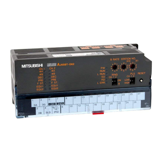
Page 26: Part Identification Nomenclature And Settings
3. PART IDENTIFICATION NOMENCLATURE AND SETTINGS This section shows the name of each part within the high-speed counter module and explains how to set each switch. (The illustration below indicates the AJ65BT-D62). Name Description Used to set the station number of the high-speed Station number setting counter module between 1 and 61. - Page 27 HIGH side: With Phase 1 input, up to 400(200)kPPS and with switch Phase 2, up to 300(200)kPPS can be counted. The figures in ( ) are for the AJ65BT-D62. (When shipped from the factory: set at HIGH side) Set whether the ring counter function can be used.
- Page 28 Lights up when coincidence output set value No.1 = counter EQU1 value. Lights up when coincidence output set value No.2 = counter EQU2 value. (This does not exist in the AJ65BT-D62D-S1 model.) • For AJ65BT-D62 Signal name Signal name Number Number A B...
- Page 29 Name Description • For AJ65BT-D62D Signal name Signal name Number Number A B PRESET F.G. F.START EQU1 A EQU2 EQU1 B EQU2 PRESET 12/24V F.START • For AJ65BT-D62D-S1 Terminal block Signal name Signal name Number Number A B PRESET F.G. PRESET F.START A...
- Page 30 Name Description This is the same for CH2. AJ65BT-D62 Circuit board Jumper (When a jumper is connected to 5V) AJ65BT-D62D Pulse/external input voltage setting pin (When a jumper is connected to 12V) AJ65BT-D62D-S1 (When a jumper is connected to 24V)
-
Page 31: Loading And Installation
4. LOADING AND INSTALLATION Handling Precautions (1) Do not drop or apply strong shock to the module case. (2) Do not remove the module printed circuit board from the case. This will cause a breakdown. (3) Be careful not to let foreign matters such as fillings or wire chips get inside the module. -
Page 32: Installation Environment
Installation Environment Do not install the A series programmable controller in the following environment. (1) Where the ambient temperature exceeds the 0 to 55°C range. (2) Where the ambient humidity exceeds the 10 to 90% RH range. (3) Where condensation is produced by sudden temperature changes. (4) Where corrosive or combustible gas is present. -
Page 33: Wiring
5. WIRING This section explains the wiring for the high-speed counter module. Wiring Method to Each Module The following diagram shows the wiring of the master module, remote module and high-speed counter module with dedicated cable for CC- Link. Master module High-speed counter module Remote module (Blue) -
Page 34: Precautions When Wiring To The Pulse Generator
Precautions When Wiring to the Pulse Generator (1) Implement the following types of noise measures for high-speed pulse input. (a) Always use a twisted shielded wire and perform class 3 grounding. (b) Do not run the twisted wire parallel to the power cord or I/O line with a lot of noise. - Page 35 *2 Make the distance from the encoder to the joint box short. When there is long distance from the high-speed counter module to the encoder, voltage drops will occur. Therefore, use a measuring device such as a tester on the joint box terminal block to check whether the voltage while the encoder is operating and at a standstill is within the rated voltage for the encoder.
-
Page 36: Example Of Wiring For The Pulse Generator
*Set the pulse input voltage setting pin to the side. Point The wiring between the AJ65BT-D62 and the encoder should be separate from the power supply line and signal line. • An example is shown below. AJ65BT-D62 Encoder... - Page 37 (2) Example of wiring to a voltage output type pulse generator (5V DC) AJ65BT-D62 Pulse input voltage 1/3W Pulse generator setting pin* 4.7k 1/3W Shielded twisted 4.7k 1/3W pair cable Pulse input voltage 1/3W setting pin* 4.7k 1/3W Shielded twisted 4.7k...
- Page 38 Pulse generator AJ65BT-D62D-S1 Shielded twisted pair cable Shielded twisted pair cable 14050 Shielded twisted pair cable PRESET 14050 PRESET External power supply...
-
Page 39: Example Of Wiring Between A Control Device And External Input Terminals (Preset, F.start)
Example of Wiring Between a Control Device and External Input Terminals (PRESET, F.START) (1) When the control device (sink load type) is 12V AJ65BT-D62, AJ65BT-D62D, AJ65BT-D62D-S1 External Controller input voltage 1/3W setting pin* 1/3W PRESET or F.START 4.7k Shielded twisted 1/3W 4.7k... -
Page 40: Example Of Wiring To The External Output Terminals (Equ1 To Equ2)
(EQU1 to EQU2) When using an EQU terminal, an external power supply in the range of 10.2V DC to 30V DC is needed to operate the internal photocoupler. Run the wires as shown below. (1) AJ65BT-D62, AJ65BT-D62D AJ65BT-D62, AJ65BT-D62D Load EQU1... -
Page 41: External Dimensions
6. EXTERNAL DIMENSIONS 2- 4.5 mounting hole 142.9 (5.63) 151.9 (5.98) (Unit: mm (in.)) 7. Information for the Chinese Standardized Low... - Page 42 Memo...
- Page 43 Memo...
- Page 44 20 Waterford Office Park, 189 Witkoppen Road, Avenida Adelino Cardana, 293, 21 andar, Fourways, South Africa Bethaville, Barueri SP, Brazil Tel : +27-11-658-8100 Tel : +55-11-4689-3000 Germany MITSUBISHI ELECTRIC EUROPE B.V. German China MITSUBISHI ELECTRIC AUTOMATION (CHINA) Branch LTD. Mitsubishi-Electric-Platz 1, 40882 Ratingen, No.1386 Hongqiao Road, Mitsubishi Electric...