Table of Contents
Advertisement
Quick Links
Download this manual
See also:
User Manual
Advertisement
Table of Contents

Related Manuals for microHAM microKEYER II


Summary of Contents for microHAM microKEYER II
- Page 1 © 2008 All rights reserved microKEYER II microHAM fax: +421 2 4594 5100 e-mail: support@microham.com homepage: www.microham.com Version 7.4 23 November, 2008...
-
Page 2: Table Of Contents
3. PANEL DESCRIPTION ........................5 Front Panel ........................... 5 Rear Panel ............................ 6 4. INSTALLATION ............................ 8 Preparing microKEYER II for Use....................8 Installing microHAM USB Device Router ..................9 Configuring microHAM Codec .....................10 Configuring microHAM USB Device Router ................11 Creating and Using Virtual Serial Ports .................. -
Page 3: Features And Functions
© 2008 All rights reserved 1 - FEATURES AND FUNCTIONS General: single USB connection to computer • stand alone CW and FSK operation • Complete "Computer <-> Radio" galvanic isolation • transformer isolation of sound card and radio •... -
Page 4: Important Warnings
© 2008 All rights reserved Voice (SSB/AM/FM): front panel headset jacks • rear panel hand/desktop microphone jack • automatic microphone selection • selectable preamplifiers allow electret and dynamic microphones in any combination • Digital Voice Keyer with nine messages up to 120 seconds and unlimited “banks”... -
Page 5: Panel Description
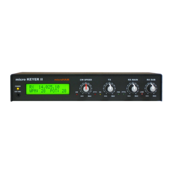
© 2008 All rights reserved 3 - PANEL DESCRIPTION Front Panel 1. EXT MIC Connection for headset mic, e.g. Heil ProSet 3.5 mm stereo - jumper select TIP - Dynamic Mic RING - Electret Mic/Bias SHELL – GND 2. CW LED flashes with CW output 3. -
Page 6: Rear Panel
© 2008 All rights reserved Rear Panel 1. DC 13.8V Power Supply - 2.1 x 5.5 mm coaxial jack, center is + IMPORTANT WARNING: Be sure to observe the proper polarity! 2. MONI Mono output for monitor speaker Connector: 3.5mm TIP - Audio RING –... - Page 7 © 2008 All rights reserved 10. PA PTT PTT output for Power Amplifier. Output (Solid State or RElay contact) depends on RE/SS jumper position. Connector: RCA, when active goes to ground. TIP – Signal SHELL – Ground If the jumper is in the SS position, the switching transistor (open collector) is connected to the PA PTT jack.
-
Page 8: Installation
(round) connector, use the adapter supplied with the cable set. If the station microphone uses an electret element (most Icom radios), open microKEYER II and place the Electret jumper located just in front of the three trimmers in the center of the board on both pins. -
Page 9: Installing Microham Usb Device Router
© 2008 All rights reserved Installing microHAM USB Device Router To install Router click on the Install USB Device Router link on the installation CD or download the most recent installation package from the web site: www.microham.com/contents/en-us/d29.html If you download an updated package, click on "urouter_release_xx_xx.exe"... -
Page 10: Configuring Microham Codec
© 2008 All rights reserved Configuring microHAM CODEC Windows will automatically install the USB Audio Device driver to support the microHAM CODEC in MK II. Windows automatically selects any newly installed audio device as the default device for Sound playback and Sound recording. -
Page 11: Configuring Microham Usb Device Router
The software interface is provided as Virtual Serial Ports. In order to configure and use microKEYER II with Windows compatible application programs, you must be running Router and have turned on microKEYER II. Router is then configured as required by the application (logging, control or digital mode) software. -
Page 12: Creating And Using Virtual Serial Ports
Router provides a set of virtual serial ports which allow Windows applications (logging and digital software) to work with microKEYER II just as they would work with "real" (hardware) serial ports. In order to use these virtual Ports, you must first create the ports and then assign a port to each function you wish to use (radio control, PTT, CW, FSK, etc.). -
Page 13: Microham Usb Device Router
(sound card) in the appropriate fields at Audio Mixer tab and will actively control the audio devices Automatically assign microHAM audio devices: when checked, Router will automatically assign proper audio device of the same name if multiple microHAM interfaces of the same kind are connected to the one computer. Options | DVK: Voice message time limit: maximum time for each voice message up to 120 seconds. -
Page 14: Menu: Preset
FSK, PTT, and the sound card its own way. In some cases, what works for one application may not work properly with another. To get maximum performance from microKEYER II, the user should create customized settings for each application used. -
Page 15: Menu: Device
When clicked, Router will open a standard File dialog – the default location is: C:\Documents and Settings\All Users\Application Data\microHAM\cfg - and the desired template can be chosen. When Router loads a template, it looks for an html or txt file with the same name as the template in the... -
Page 16: Menu: Virtual Port
Keyboard, Display and System tabs to the microKEYER II's EEPROM. If microKEYER II is operated without connection to the computer it will use the settings stored in EEPROM. If microKEYER II is connected to a computer running Router, the power-up settings will be overridden by the Router settings but the default settings are retained in EEPROM. -
Page 17: Menu: Help
About: Shows the Router's internal version number DEVICE CONFIGURATION TABS There are eleven (11) tabs for configuring microKEYER II. Each tab controls part of microKEYER II's functions. Except for CW Messages and FSK Messages, any change is applied immediately. Ports: assign virtual ports to the microKEYER II for use by applications ●... -
Page 18: Ports Tab
Router then in the application. Correct port assignment is critical for proper operation with application software. microKEYER II has 11 channels – each channel provides an indication of the settings applied by the application and current state (e.g., or or off): CAT (uses RxD and TxD) ●... -
Page 19: Nd Cat
CAT is not reliable because RFI can prevent the radio from switching back to receive. In addition, microKEYER II cannot control an amplifier when the application uses PTT by CAT since it has no way to sense that the the application has placed the transceiver into transmit. There is a dedicated T/R switching channel for this purpose called PTT. - Page 20 © 2008 All rights reserved Disable router queries – When this box checked, Router will not poll the radio for frequency and mode when that information is not available from the communication between the application and radio. NOTE: "Disable router queries" disables Router polling only when the port has been opened by an application program.
-
Page 21: Fsk & 2
© 2008 All rights reserved NOTE: Although Router has been tested extensively using many different applications for the CAT and 2 ports, microHAM cannot guarantee proper operation with every possible combination of software. FSK & 2 FSK PORTS The FSK channels are used by application programs to send the FSK keying signal. FSK is used primarily for RTTY. -
Page 22: Ports: Cat & 2 Ports: Fsk & 2 Ports: Cw
© 2008 All rights reserved PTT: The virtual port used for FSK can also support PTT (required by MMTTY). When you use MMTTY, select the PTT box and RTS will used for PTT. Do not use the FSK port for any other function. -
Page 23: Ports: Foot Switch
© 2008 All rights reserved PTT & 2 PTT PORTS The PTT channels are used to control transmit/receive switching of the transceiver and power amplifier. An internal sequencer assures 100% protection against hot switching of the PA when the PTT channel is used. -
Page 24: Ports: Winkey
© 2008 All rights reserved WinKey PORT WinKey is a unique external CW processor developed by Steve Elliot, K1EL. This CW processor supports paddle input like any other electronic keyer, offers many configuration options, and in addition converts ASCII data from the computer to Morse characters. This unique property assures perfectly timed CW output from the computer regardless of OS load. -
Page 25: Ports: Auxiliary
If a line ends in three dots (...) it means that the command or response has been broken across two USB packets. CONTROL PORT The Control Port allows an application program (logger) that implements the microHAM Control Protocol to make use of microKEYER II's CW, FSK and DVK message memories When an application opens the control port, Router reports port as open and displays settings used to configure COM port. -
Page 26: Audio Switching Tab
© 2008 All rights reserved AUDIO SWITCHING TAB microKEYER II uses an advanced, custom USB audio subsystem which allows Router to handle all of the audio routing. Microphone and receive audio are always connected to microHAM CODEC (the microKEYER II “sound card”). - Page 27 The black box will show the selected microphone. Transmit Monitor: microKEYER II includes a monitor ampflier that provides 2 watts to a user supplied speaker. Router will select the audio source to be monitored based on the operating mode. The monitor level can be set independently for each source/mode.
-
Page 28: Audio Mixer Tab
If Stereo is not selected, the Audio Mixer tab will display a single set of controls and will mute the right channel. MicroKEYER II uses the left channel for all output but in some cases you may want to use the right channel for another purpose. - Page 29 MASTER only if necessary to keep the WAVE control from operating at one end of its range. Test Signal: causes microKEYER II to output a 1500 Hz audio tone for setting the transmit output level for AFSK digital modes.
- Page 30 Note, the display is active only if a sample rate is selected. microKEYER II shows one sliders for each input – Left for the Main RX and Right for the Sub RX. Keep the sliders at about 80% and use the RX Main and RX Sub pots on the front panel for adjustment.
-
Page 31: Ptt Tab
● PTT OUTPUTS microKEYER II has four PTT outputs: PTT1, PTT2, PAPTT and LNA PTT. PTT1 and PTT2 are brought out to the DB37 Radio connector. PAPTT and LNA PTT are RCA jacks for connecting to external devices. PTT1 is wired to the radio microphone jack and is generally used for VOICE modes. - Page 32 © 2008 All rights reserved MicroKEYER II can select the PTT output based on the mode, and optionally frequency, reported by the transceiver in response to polling by the application (logger) and/or Router. If Router is not able to read the operating mode from your radio (radio does not have computer control port or does not report usable mode information), you can select one of four fixed “no radio”...
-
Page 33: Cw/Winkey Tab
© 2008 All rights reserved CW/WinKey TAB This tab provides the configuration for the WinKey based, internal CW keyer. A complete WinKey manual can be downloaded from: http://k1el.tripod.com/docfiles.html. Thanks to Steve Elliott, K1EL for this great product. WinKey can be controlled by a logging program or operate in stand alone mode controlled by Router. -
Page 34: Cw Messages Tab
Test: plays a message without storing it Store: saves one message to microKEYER II memory Store All: saves all messages to microKEYER II memory Load from File: loads all messages from file... -
Page 35: Fsk Messages Tab
Delay: sets the delay in seconds before looping or calling another message Store: saves one message to microKEYER II memory Store All: saves all messages to microKEYER II memory Load from File: loads all messages from file... -
Page 36: Dvk Tab
© 2008 All rights reserved DVK TAB microKEYER II allows recording and playing an unlimited number of messages (limited only by the capacity of the computer hard drive) - nine voice messages per bank. Banks can be managed with Rename, Add and Remove buttons. -
Page 37: Keyboard Tab
© 2008 All rights reserved KEYBOARD TAB The Keyboard Tab controls the operation of a PS/2 keyboard or numeric keypad connected to the PS/2 jack. It is also possible to define control functions for the numeric keypad. Custom controls are invoked by pressing and holding the asterisk key (*) with Numkey0-9. -
Page 38: Display Tab
Light: sets the LCD backlight brightness Report time: sets the length of time that transient (status change) reports remain visible Set Strings: set the “Welcome Message” to be displayed when microKEYER II is initialized. Set Defaults: returns the display to factory settings... -
Page 39: System Settings Tab
“Auxiliary” virtual port defined on Ports tab and the iLINK serial lines without modification. Maximum data rate is 19,200 baud. SteppIR: When Serial port function is set to SteppIR, microKEYER II can control a SteppIR antenna using SteppIR's native protocol via the SteppIR “Data Out” Port. For information concerning the “Data Out”... -
Page 40: Setting Audio Levels
© 2008 All rights reserved 6 – Setting Audio Levels For optimum operation microKEYER II audio levels must be set properly. The function of each control was described in the AUDIO MIXER and DVK sections of the manual. Following a step-by-step approach will help you to set proper levels. -
Page 41: System Considerations
ALC zone (the same level as steps 9 and 11). 7 - System Considerations microKEYER II can be used with a wide variety of software. The capabilities of those packages will have large influence on the level of computing power needed to utilize microKEYER II. -
Page 42: External Keyboard/Keypad
NOTE: The keyboard/Keypad must be PS/2. A USB device with PS/2 adapter will not work properly. microKEYER II includes the ability to generate FSK or CW, record and play CW, FSK or VOICE messages using a PS/2 keyboard or numeric keypad connected to the PS/2 jack. A numeric key pad is sufficient to record and play CW and DVK messages, control CW speed (WPM) or play a serial number message. - Page 43 © 2008 All rights reserved Voice std. key Numeric Keypad mode mode mode start/stop recording of message (recording mode is NUM LOCK indicated by NUM LED) Tune (can be canceled by keys NUM 0 or ESC, or by the...
-
Page 44: Hardware Specifications
© 2008 All rights reserved 9 - HARDWARE SPECIFICATIONS USB: USB 2.0 Full speed, USB 1.1 compatible Power consumption: USB – less than 100mA Power supply – 400mA at 13.8V (max. 16V) Radio Port: RxD, TxD – max. 57,600 Baud, RTS/CTS handshake supported... -
Page 45: Package Contents
SLOVAKIA 11 - WARRANTY microHAM warrants microKEYER II for three (3) years. The product must not be modified in any way except configuration, or the warranty is voided. The warranty does not cover damage caused by improper or abnormal use, failure to follow instructions, improper installation, lightning, or excessive voltage. The product will be either repaired or replaced, at our discretion. -
Page 46: Declaration Of Conformity
© 2008 All rights reserved DECLARATION OF CONFORMITY Federal Communications Commission Statement (USA) This device complies with Part 15 of the FCC Rules. Operation is subject to the following two conditions: (1) this device may not cause harmful interference, and (2) this device must accept any interference received, including interference that may cause undesired operation. -
Page 47: Appendix A - Connectors
© 2008 All rights reserved APPENDIX A – DB37 RADIO CONNECTOR Pin # Label Description No contact RS232 RTS RS232 radio port RTS output RS232 CTS RS232 radio port CTS input IF-FIF iface matrix - used for configuring desired levels for radio control interface... - Page 48 © 2008 All rights reserved ILINK – miniDIN 6 Pin # Label Description DATA I2C Data channel for expansion (TTL) RX EXT Serial Data In (TTL) Connected to system ground and case +5 V +5V output, max.100mA. CLOCK I2C Data Clock (TTL)
-
Page 49: Appendix B - Rfi Considerations
It is absolutely important to prevent ground currents from flowing to the common ground point by way of the signal cable. If you use a microHAM "keyer," a good test is to remove the DB15/DB37 connector and USB cable from the keyer and measure the resistance from the shell of the DB15/DB37 to the shell of the USB cable.